Spaceborne GPS receiver antenna phase center off set and variation estimation for the Shiyan 3 satellite
Gu Defeng,Lai Yuwang,Liu Junhong,Ju Bing,Tu Jia
College of Sciences,National University of Defense Technology,Changsha 410073,China
Spaceborne GPS receiver antenna phase center off set and variation estimation for the Shiyan 3 satellite
Gu Defeng*,Lai Yuwang,Liu Junhong,Ju Bing,Tu Jia
College of Sciences,National University of Defense Technology,Changsha 410073,China
In determining the orbits of low Earth orbit (LEO) satellites using spaceborne GPS,the errors caused by receiver antenna phase center offset (PCO) and phase center variations (PCVs) are gradually becoming a major limiting factor for continued improvements to accuracy.Shiyan 3,a small satellite mission for space technology experimentation and climate exploration,was developed by China and launched on November 5,2008.The dual-frequency GPS receiver payload delivers 1 Hz data and provides the basis for precise orbit determination within the range of a few centimeters.The antenna PCO and PCV error characteristics and the principles influencing orbit determination are analyzed.The feasibility of PCO and PCV estimation and compensation in different directions is demonstrated through simulation and in-flight tests.The values of receiver antenna PCO and PCVs for Gravity Recovery and Climate Experiment(GRACE)and Shiyan 3 satellites are estimated from one month of data.A large and stable antenna PCO error,reaching up to 10.34 cm in the z-direction,is found with the Shiyan 3 satellite.The PCVs on the Shiyan 3 satellite are estimated and reach up to 3.0 cm,which is slightly larger than that of GRACE satellites.Orbit validation clearly improved with independent k-band ranging (KBR) and satellite laser ranging (SLR) measurements.For GRACE satellites,the average root mean square (RMS) of KBR residuals improved from 1.01 cm to 0.88 cm.For the Shiyan 3 satellite,the average RMS of SLR residuals improved from 4.95 cm to 4.06 cm.
1.Introduction
Given its all-weather availability,high precision and good continuity,spaceborne dual-frequency GPS has been successfully applied in the field of satellite navigation.With the development of GPS precise orbit determination (POD) technology,an increasing number of low Earth orbit (LEO) satellites1–3are being equipped with dual-frequency GPS receivers.Such receivers have become among the most important instruments in LEO satellite POD.Orbits established with spaceborne dual-frequency GPS technology are precise to within several centimeters.4–6Neglected or mismodeled antenna phase center offset (PCO) and phase center variations (PCVs),which can be attributed to ground calibrations,deformation,fuel consumption and satellite in-flight environment,have gradually become among the most important systematic error sources in LEO GPS data processing.7,8This has lead to a need to perform in-flight determination of antenna PCO and PCVs.The first in-flight calibrations for spaceborne receiver antennas were generated for JASON-1.9In-flight calibrations have been adopted for more and more satellites to meet high precision orbit requirements,including Gravity Recovery and Climate Experiment (GRACE),10–12TerraSAR-X,10,13,14COSMIC,15GOCE16and Haiyang 2A.17
Antenna PCO is generally defined as an offset from antenna reference point (ARP) to mean center of the wavefront in the respective antenna-fixed system (AFS).18ARP is a mechanical point that has been conventionally defined by the International GNSS Service (IGS)as the intersection of the vertical antenna axis of symmetry with the antenna bottom.19A priori PCO vectors in AFS and the coordinates of ARP with respect to the satellite center of mass (COM) in the satellite body system (SBS) are usually provided by ground calibrations.In this study,PCO is redefined as an offset from COM to the mean phase center in spaceborne application.Thus,an a priori PCO vector with respect to COM in SBS can be obtained before launching.Three main error sources for the a priori PCO vector should be considered.The first is ground calibration error,especially for COM.To remain consistent with inflight conditions,solar panels will be kept unfolded during ground calibrations.The second source is fuel consumption caused by orbital maneuvers.The third is deformation caused by gravity and in-flight temperature variations.COM coordinates of the TanDEM-X satellite were off by 7 mm after launch.The fuel tank of the satellite will be empty due to regular orbit and formation control maneuvers,thereby causing a shift in the COM of up to 10 cm over the life of the satellite.A regular update of PCO coordinates is therefore required to ensure high accuracy in orbit determination for the TanDEM-X satellite.14
In practice,the wavefront will fluctuate because of the antenna manufacturing characteristics,and the signal reception locations do not coincide.The receiver antenna phase center is the instantaneous location where the GPS signal is actually received,and is dependent on signal frequency and reception direction.Antenna PCVs describe the directiondependent distortions of the wavefront,which can be modeled as the distance between the instantaneous location and the mean phase center.An a priori absolute PCV pattern for each frequency can be obtained from ground robot-field calibrations or anechoic chamber calibrations in AFS before launching.17However,ground calibrations are performed without or with only limited information related to the in-flight environment and are insufficiently accurate.16Systematic effects (e.g.,near-field multipath) encountered in the actual antenna environment must be considered.Therefore,in-flight estimation and compensation for antenna PCVs are necessary in high-precision orbit determination applications.
This study focuses on the in-flight calibrations of antenna PCO and PCVs of the Shiyan 3 satellite.In order to avoid the influence of measurement errors on the location of the signal transmitting reference points from GNSS satellites,transmitting antenna PCO and PCVs of GNSS satellites need to be given first.The IGS provides the antenna information exchange file,i.e.igs08.atx,20which consists of a set of receivers and GNSS satellite absolute antenna PCO and PCVs.Ground-based absolute calibration results from the anechoic chamber of Shiyan 3 choke ring antenna are available.However,calibrations were performed with limited information related to the satellite environment,and were inconsistent with in-flight calibrations.For validation of general effectiveness and comparison of in-flight calibration results,GRACE data tests were also performed.First,an antenna PCO and PCV estimation model was established.The error characteristics and influence principles of this estimation model on orbit determination were analyzed.The feasibility of PCO and PCV in-flight estimation and compensation in different directions was demonstrated by simulation tests.Subsequently,the values of antenna PCO and PCVs for GRACE and Shiyan 3 satellites were estimated from one month of in-flight data.Finally,orbit improvement is validated through orbit overlap analysis and independent k-band ranging (KBR) and satellite laser ranging (SLR) measurements.
2.Antenna PCO and PCV estimation model
The adopted antenna PCO and PCV model is based on the well-known antenna PCV correction equation17where the total antenna phase center correction in the direction of the GPS satellite consists of an absolute mean PCO plus the elevation and azimuth dependent PCVs.Fig.1 shows Antenna PCO and PCV estimation model.When an a priori PCO vector or a priori PCV pattern in AFS is derived from ground calibrations,the vector or pattern has to be converted to SBS.The relation between AFS and SBS should be determined.For convenience,AFS is defined as follows:the origin is ARP,the positive z-axis coincides with the mechanical symmetry axis and points along the boresight direction,and the x-and y-axes point from ARP into their respective directions depending on the specific mounting of the antennas.For the Shiyan 3 satellite,the three axes of AFS coincide with SBS.For GRACE satellites,the x-axis of AFS coincides with the x-axis of SBS,but the y-axis of AFS is in opposite direction of the y-axis of SBS,and the z-axis yields a right-handed coordinate system.In AFS,the azimuth angle α of a unit line-of-sight(LOS)vector e is defined as an angle between the projection of e in the xOy-plane and positive x-axis.This angle is counted in a counter-clockwise direction from the x-axis to the y-axis.The elevation angle β of vector e is defined as an angle between e and the xOy-plane.
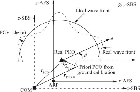
Fig.1 Antenna PCO and PCV estimation model.
The first step involves the estimation of the PCO error components.rPCOis the real PCO vector with respect to COM in SBS;rPCO,0is an a priori PCO vector that can be calculated from ground calibrations;and ΔrPCOrepresents the PCO bias caused by ground calibrations or in-flight variation,i.e.(see Fig.1).ΔrPCOmakes the a priori PCO vector rPCO,0inaccurate,and will induce an elevation and azimuth dependent distance bias in the antenna PCO correction.The real distance correction caused by PCO is given by

where ejis a LOS vector from the COM of LEO satellite to the COM of GPS satellite j in the inertial reference system J2000;is the attitude rotation matrix from SBS to J2000;and ΔrPCOis a systematic bias and can be considered as a constant vector.
In the second step,the elevation and azimuth dependent phase pattern can be modeled and estimated by following the 'residual approach' described by Ja¨ggi et al.8,10The unknown PCVs can be considered as a function dφ(αj, βj).The real distance correction caused by PCVs is

where αjand βjrepresent azimuth angle and elevation angle of ej;λiis the carrier wavelength of frequency i.
The phase residuals can be obtained by observation minus computation from orbit post-fit model(O-C).Dual-frequency ionosphere-free(IF)combination observations are adopted.For carrier phase observations the ionosphere-free combination yields

where the subscripts 1 and 2 denote the different frequencies;LIFis the phase ionosphere-free combination;tiis the signal reception time;fis the carrier frequency;L is the phase observation of frequency f;ρjis the geometric distance from the LEO satellite to the GPS satellite;δtris the receiver clock error;δtjis the GPS satellite clock error;c is the speed of light;λIFAIFis the ambiguity of phase ionosphere-free combination;and εjcontains thermal measurement noise,multipath and all other unmodeled errors.The geometric range

is simply given as the distance between the antenna phase center location of the GPS receiver r(ti)at signal reception time,and the GPS satelliteat signal emission time.τjis the signal path delay,which can be obtained by iterative calculation.δρcorrrepresents all kinds of correction,


where δρPCV,i(ej)is the receiver antenna PCV correction for the phase observation Li.
Assuming that the distance computation by orbit post-fit model without PCV correction in epoch tiisand the ionosphere-free phase observation isthe n ionosphere free phase O-C residuals can be expressed as

According to this model,antenna PCO and PCV estimation has been added to NUDTTK,which is a POD toolkit developed by the National University of Defense Technology.A summary of the dynamic and measurement models used for GPS based LEO satellite orbit determination is given in Table 1.
3.Antenna PCO estimation test
3.1.Simulation I:effect of PCO error on orbit determination
The effect of PCO error in different directions on orbit determination is analyzed in Simulation I.One week dual-frequency GPS observations are first simulated.Three different simulations are performed in Simulation I,in which a 10 cm antenna PCO error is added to the simulated observations in all x,y and z directions,The reference LEO satellite orbit,SIMU-REF,is obtained by the post-fit orbit of the GRACE A satellite science orbit product over a period of 7 days(January 1,2006 to January 7,2006).Without receiver antenna PCO correction,GRACE A orbit determination results,SIMU-noPCO,are then obtained through the reduceddynamic approach on the basis of simulated data.Comparing SIMU-noPCO and SIMU-REF,the simulation results for the effect of PCO error in different directions on orbit determination are shown in Table 2.The RMSs of orbital position errors are given in radial(R),transverse(T)and normal(N)directions.Here,a three-axis stabilized attitude is used by the LEO satellite,and the x-direction coincides with T-direction,the y-direction corresponding to N-direction,the z-direction corresponding to R-direction.

Table 1 Summary of dynamic and measurement models used for GPS-based LEO satellite orbit determination in NUDTTK.
The effects of antenna PCO error in different directions on orbit determination are significantly different.The x-direction coincides with satellite flight direction.A 10 cm PCO error in the x-direction,can induce a constant orbit offset of the same size in the transverse(T)direction.The average RMSs of radial(R),transverse(T)and normal(N)orbital position errors are 0.010,10.000 and 0.007 cm,respectively.The y-direction corresponds to the normal orbit direction.A 10 cm PCO error in the y-direction,can induce a constant orbit offset of the same size in the N-direction.The average RMSs of R,T and N orbital position errors are 0.005,0.015 and 10.004 cm,respectively.The z-direction corresponds to the orbit R-direction.A 10 cm PCO error in the z-direction,does not induce a constant orbit offset of the same size in one direction but results in irregular fluctuations in three directions.The average RMSs of R,T and N orbital position errors are 1.234,1.479 and 1.794 cm,respectively.The average RMS in three dimensions is 2.634 cm,only a quarter of the 10 cm simulation,and some are smoothed out by dynamic orbit fitting.
3.2.Simulation II:feasibility of PCO error estimation
The feasibility of PCO error estimation in different directions is analyzed in Simulation II.Aside from the 10 cm antenna PCO error,random Gaussian white noise is also added to the simulated observations with the standard deviation values of σP1= σP2=50 cm, σL1= σL2=0.2 cm.One week dual frequency GPS observations are re-simulated,and three simulations are conducted with different PCO error vectors:andAccording to Eq.(2),antenna PCO error is considered as a constant vector.Parameter estimation in the x,y and z-directions is performed.When one of the directions is estimated,the other two directions are fixed at zero.The daily antenna PCO error estimation results are shown in Table 3.The column 'x-direction estimation' refers to the simulation withthe column 'y-direction estimation' refers to the simulation withand the column 'z-direction estimation' refers to the simulation with
The PCO error estimation results in different directions significantly differ.The daily estimation results in the z-direction are stable and almost equal to 10 cm.The average PCO estimation result in the z-direction is 10.01 cm,which is the value nearest to the original 10 cm antenna PCO error among all three directions.The standard deviation of daily estimationresults in this direction is only 0.016 cm,which indicates that the PCO estimation accuracy in the z-direction is very high.In NUDTTK software,empirical accelerations in the R-direction are not used.Consequently,the PCO in the z-direction can be estimated without any conditions.If R-direction empirical accelerations are switched on,we must set a condition for the PCO estimate in the z-direction,e.g.,the mean value of empirical accelerations in the R-direction is constrained to zero.

Table 2 Simulated effect of 10 cm-size antenna PCO error in different directions on orbit determination.

Table 3 Simulation of antenna PCO error estimation in different directions.
The daily estimation results in the y-direction are unstable and not very close to 10 cm.Although the average PCO estimation result in the y-direction is near 10 cm,the standard deviation of daily estimation results is 7.61 cm,which is significantly larger than that in the z-direction.The main reason for this is that the y-direction PCO estimation is coupled with the N-direction empirical force parameters(see Table 1).Estimating these two kinds of parameters together without any conditions will make the solution unstable.
The daily estimation results in the x-direction are worse.The standard deviation of daily estimation results reaches 550.8 cm.The estimation results of days 1 and 2 are larger than 1.0 m,which indicates that the x-direction PCO estimation without any condition will make the algorithm difficult to converge.This is because the x-direction PCO estimation is coupled with T-direction empirical force parameters.Simulation II indicates that the use of GPS data to estimate PCO error precisely is feasible in the z-direction,but is unstable in the y-and x-directions.Hence,we sometimes only estimate z-direction PCO error in certain LEO satellite orbit determination applications by GPS.8
3.3.Antenna PCO estimation results for GRACE satellites
GRACE21is a satellite gravity field measurement system developed by Germany's Deutsches Zentrum fu¨r Luft- und Raumfahrt and America's National Aeronautics and Space Administration.It consists of two identical formation-flying satellites,GRACE A and GRACE B.On March 17,2002,the twin satellites were launched into an almost circular,near polar orbit with an inclination of 89°and an altitude of 500 km.The distance between the two satellites is approximately 220 km.The GRACE satellite payload includes a KBR system,dual-frequency GPS receiver,laser reflector,accelerometer and star sensor.The KBR,which is mainly for detecting changes in Earth's gravity field,can be used to verify inter-satellite baselines with precision.
The original antenna PCO vectors for GRACE satellites are given in the related SBS published by Kroes.22Over a period of 31 days(January 1,2006 to January 31,2006),GRACE A and GRACE B dual-frequency GPS observations were processed to estimate daily antenna PCO errors in the z-direction with respect to the a priori PCO vector(see Fig.2).The mean value of daily antenna PCO error estimation results for GRACE A is 0.59 cm,which equals the mean PCO estimation(-40.81 cm)minus the original PCO of GRACE A(-41.40 cm),and the standard deviation is 0.12 cm;the mean value of daily PCO error estimation results for GRACE B is 0.34 cm,which equals the mean PCO estimation(-41.09 cm)minus the original PCO value of GRACE B(-41.43 cm),and the standard deviation is 0.12 cm.The mean values are very small,which means the a priori antenna PCO value for GRACE satellites from ground calibrations is accurate.The standard deviations are also small,indicating that the consistency of daily estimation results is good.Based on GRACE in-flight data tests,it is feasible to use GPS data to estimate PCO error precisely in the z-direction.
3.4.Antenna PCO estimation results for Shiyan 3 satellite
Shiyan 3 is a small satellite mission developed by China and used to test new technologies for exploring space,the atmosphere and its environment.23On November 5,2008,the Shiyan 3 satellite was launched into a sun-synchronous orbit with an inclination of 90°and an altitude of 791 km.The Shiyan 3 satellite payload includes a dual-frequency GPS receiver,laser reflector and star sensor.
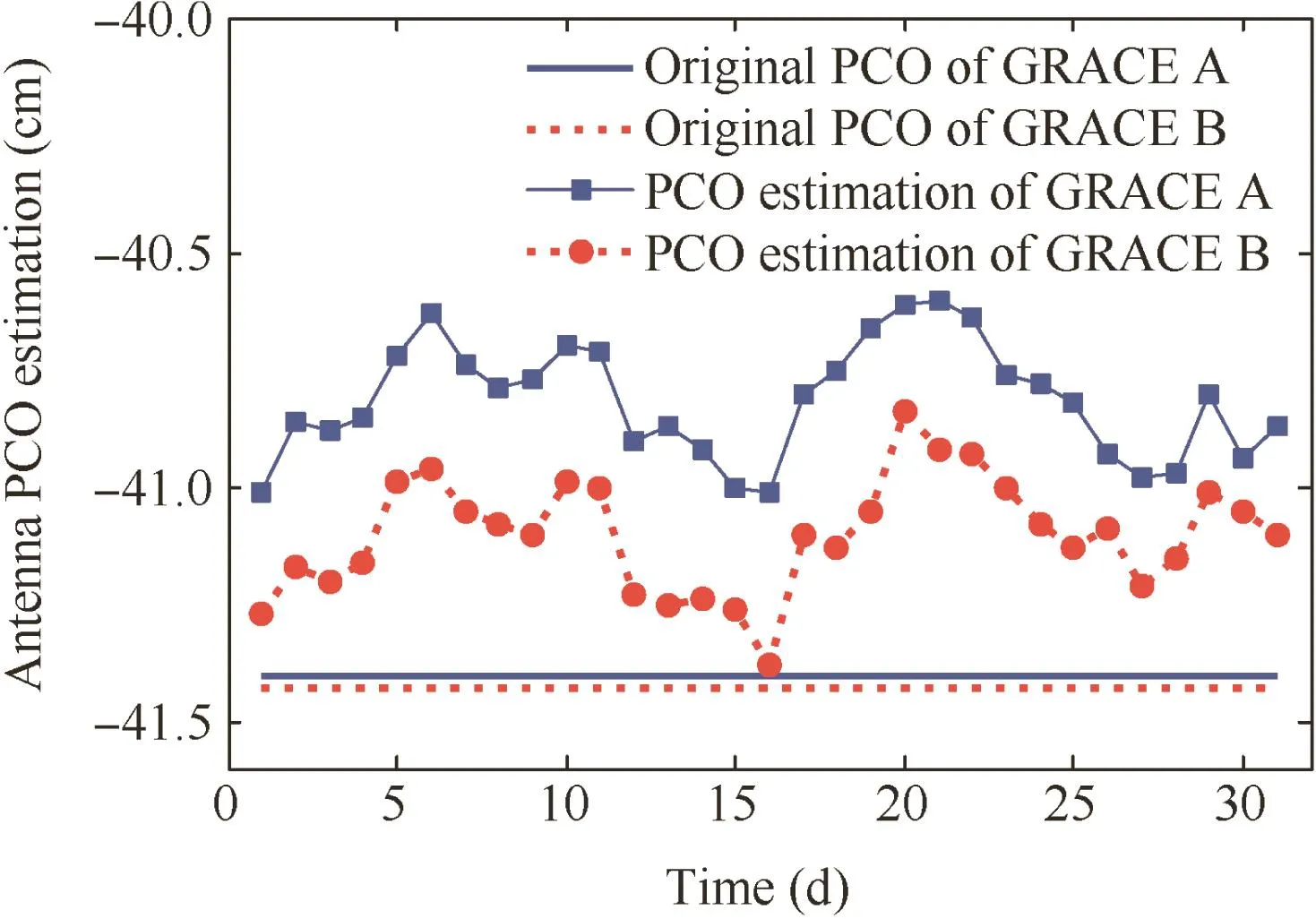
Fig.2 Daily GPS receiver antenna PCO estimation results in z-direction for GRACE satellites.
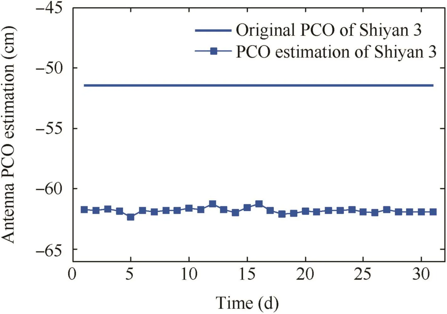
Fig.3 Daily GPS receiver antenna PCO estimation results in z-direction for Shiyan 3 satellite.
The original antenna PCO vector for the Shiyan 3 satellite is given by the satellite manufacturer.Over a period of 31 days(December 1,2008 to December 31,2008),Shiyan 3 dual frequency GPS observations were processed to estimate daily antenna PCO errors in the z-direction with respect to the a priori PCO vector(see Fig.3).The mean value of daily antenna PCO error estimation results is-10.34 cm,and the standard deviation is 0.21 cm.A large mean value of 10 cm level is found,which reflects the inaccuracy of the a priori antenna PCO value from ground calibrations.However,the standard deviation is small,which means that the consistency of daily estimation results is good.
4.Antenna PCV estimation test
4.1.Simulation III:feasibility of PCV estimation
The feasibility of PCV estimation in different directions is analyzed in Simulation III.First,an antenna phase pattern is selected as a reference.The effects of this phase pattern on distance are added into the simulated observations according to Eq.(2).The phase pattern of SEN67-1575-14+CRG antenna from ground calibrations by automated absolute field approach8,24is selected as a reference,while SEN67-1575-14+CRG is a typical choke ring antenna,and has been successfully used in TanDEM-X mission for dual-frequency GPS signal reception,see Fig.4.Fig.4(a)shows that the phase pattern of the ionosphere-free combination is almost perfectly symmetric with respect to the boresight axis.The phase pattern has the obvious character of systematic deviation.The maximum value for the mean PCVs on ionosphere-free combination can reach 1.5 cm.
Subsequently,without receiver antenna PCV correction,GRACE A orbit determination results,SIMU-noPCV,are obtained by a reduced dynamic approach using simulated observations.Comparing SIMU-noPCV and SIMU-REF,the effect of the reference phase pattern on orbital position in three directions is shown in Fig.5(a).The average RMSs of R,T and N orbital position errors are 2.6,4.6 and 3.0 mm,respectively.The average RMS in three dimensions is 6.1 mm.
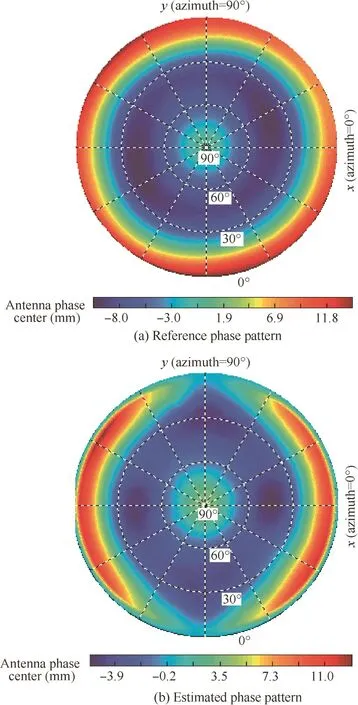
Fig.4 Phase pattern of SEN67-1575-14+CRG antenna in Tan DEM-X mission.
After three iterations,the phase pattern estimation results are obtained with 5°X5°resolution by residual approach6,10(see Fig.4(b)).The shape of the pattern corresponds well to the ground calibrated PCVs shown in Fig.4(a).Distortions of both phase patterns are similar.Most of the antenna PCVs can be effectively estimated except for y-direction,for which parts are absorbed by carrier-phase ambiguities and receiver clock parameters.
Finally,with receiver antenna PCV correction from estimation results,GRACE A orbit determination results,SIMUPCV,are obtained using simulated observations.Comparing SIMU-PCV and SIMU-REF,the improvement of orbital position accuracy by PCV estimation is analyzed(see Fig.5(b)).The average RMSs of R,T and N position errors are 0.7,1.3 and 1.3 mm,respectively.The average RMS in three dimensions is 1.9 mm.Compared with SIMU-noPCV(Fig.5(a)),position accuracy is significantly improved by PCV estimation.The average percentage of R,T and N position improvements are 73%,71%and 57%,respectively.The average percent in three dimensions is 69%.By Simulation III,the improvement of orbital position accuracy by PCV estimation is obvious.Therefore,in-flight PCV calibration and compensation are necessary in high precision orbit determination applications.
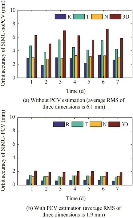
Fig.5 Influence of PCV estimation of SEN67-1575-14+CRG antenna on orbit accuracy.
4.2.Antenna PCV estimation results for GRACE satellites
First,new PCO vectors after in-flight calibration and compensation for GRACE satellites can be obtained by adding the mean value of daily PCO error estimation results into the original antenna PCO vectors(see Table 4).With new PCO correction and without PCV correction,GRACE satellite orbit determination results, GRACEA-PCO-noPCV and GRACEB-PCO-noPCV,are obtained.
Subsequently,after three iterations,the ionosphere-free phase pattern estimation results are given in Fig.6.There is no a priori PCV from ground calibrations used as an initial reference for PCV iterative estimation.The phase patterns have the obvious character of systematic deviation,closely matching the phase patterns based on 365 days of data set in 2007 as previously obtained by Ja¨ggi et al.8though with a different data set and software.The phase pattern distortions from NUDTTK software with 5°X5°resolution look a little different from those of Bernese software with 1°X1°resolution.These differences in PCV estimates might be caused by insufficient observation in some regions,such as low elevation angles.Observation data numbers in low-elevation bins are usually small,and variances of phase O-C residuals in lowelevation bins are usually large.
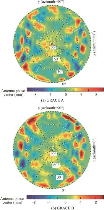
Fig.6 Ionosphere-free phase pattern estimation results for GRACE satellites.
Finally,with the estimated PCO(see Table 4)and the ionosphere-free phase pattern estimation results(see Fig.6),new PCV corrections can be performed again according Eq.(5),and GRACE satellite orbit determination results,GRACEA-PCO-PCV and GRACEB-PCO-PCV, are obtained.The influence of PCV estimation on the orbital position of GRACE satellites is given in Fig.7.

Table 4 Antenna PCO for GRACE and Shiyan 3 satellites.
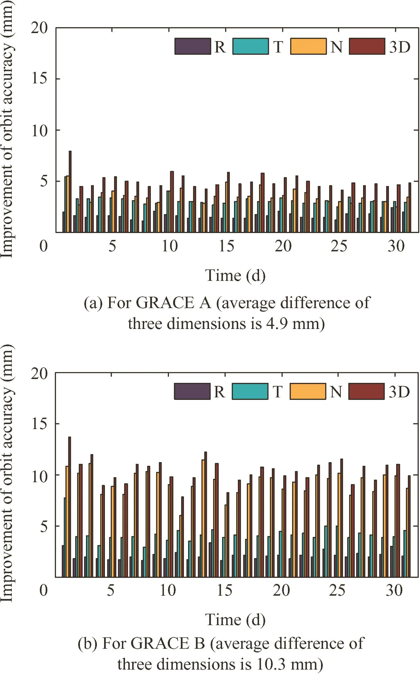
Fig.7 Influence of PCV estimation on orbital position for GRACE satellites.
Comparing GRACEA-PCO-noPCV and GRACEA-PCOPCV,the average RMSs of R,T and N position differences are 1.6,3.1 and 3.5 mm,respectively.The RMS in three dimensions is 4.9 mm(see Fig.7(a)).Comparing GRACEBPCO-noPCV and GRACEB-PCO-PCV,the average RMSs of R,T and N position differences are 2.1,4.1 and 9.2 mm,respectively.The RMS in three dimensions is 10.3 mm(see Fig.7(b)).
4.3.Antenna PCV estimation results for Shiyan 3 satellite
First,new PCO vectors after in-flight calibration and compensation for the Shiyan 3 satellite can be obtained by adding the mean value of daily PCO error estimation results into the original antenna PCO vectors(see Table 4).With new PCO correction and without PCV correction,Shiyan 3 satellite orbit determination results,Shiyan3-PCO-noPCV,are obtained.After three iterations,the ionosphere-free phase pattern estimation result is the n given in Fig.8.The phase pattern has the obvious character of systematic deviation.The maximum value for the mean PCVs can reach 3.0 cm.
Finally,with PCV correction from the phase pattern estimation result,the Shiyan 3 satellite orbit determination result,Shiyan3-PCO-PCV,is obtained.The influence of PCV estimation on the orbital position for the Shiyan 3 satellite is given in Fig.9.Comparing Shiyan3-PCO-noPCV and Shiyan3-PCOPCV,the average RMSs of R,T and N position differences are 2.8,7.9 and 5.4 mm,respectively.The RMS in three dimensions is 10 mm.The average difference of three dimensions is 10 mm.
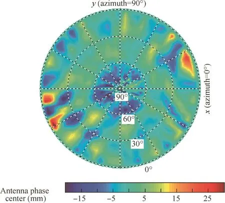
Fig.8 Ionosphere-free phase pattern estimation results for Shiyan 3 satellite.
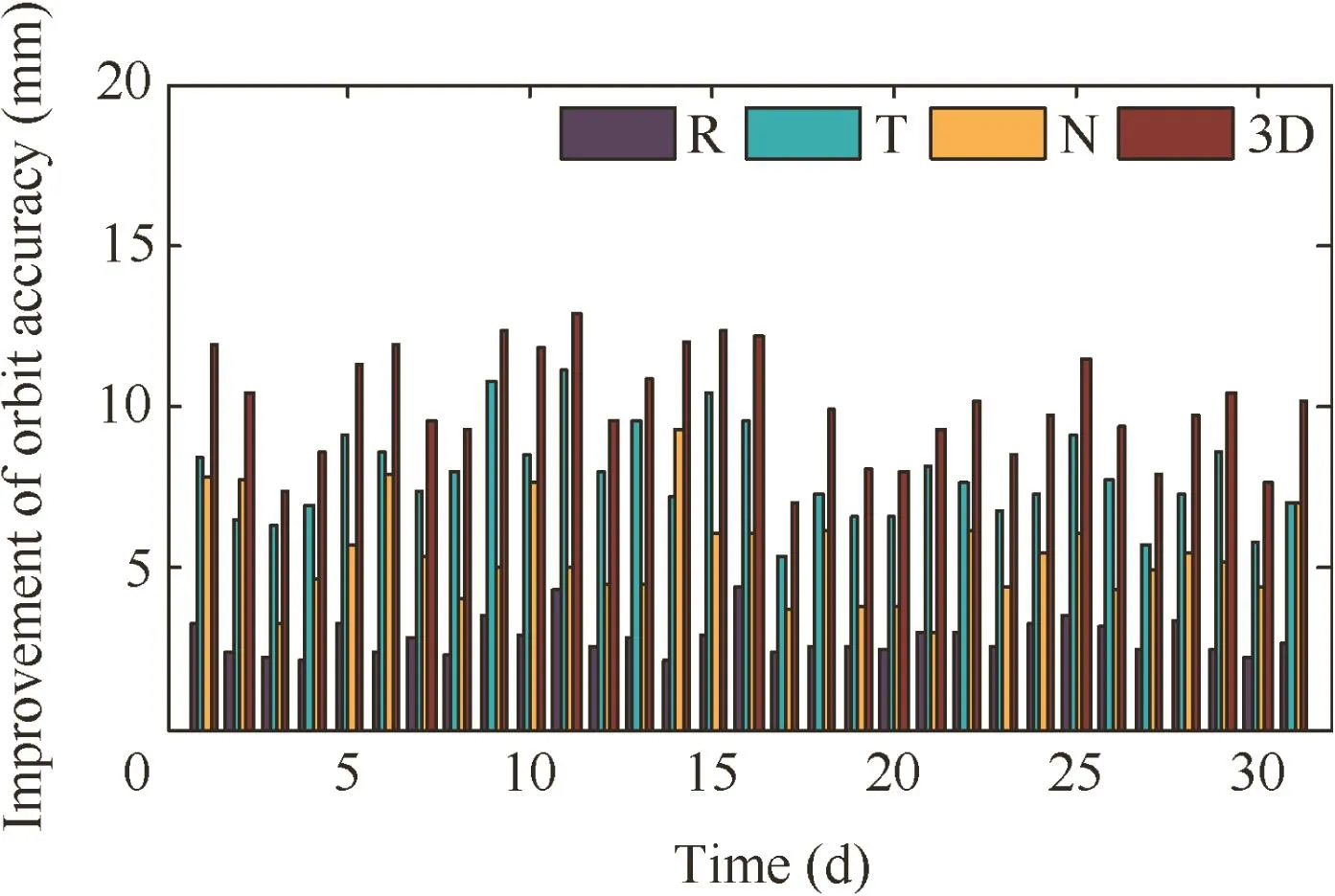
Fig.9 Influence of PCV estimation on orbital position for Shiyan 3 satellite.
5.Orbit validation
5.1.Orbit validation with KBR data
The KBR system is one of the key scientific instruments onboard GRACE satellites.It measures the one-way range change between the two GRACE satellites with the precision of approximately 10 μm at 5 s data intervals.Given the high precision of KBR data,the relative position accuracy of GRACE satellites can be validated.13,22
The relative positions computed by GRACE-noPCO-noPCV,GRACE-PCO-PCV and JPL precise science orbits are validated by KBR data(see Fig.10).The selected product type of JPL precise science orbits is GNV1B-01,which is produced by JPL's GIPSY-OASIS software.25For GIPSY-OASIS software,GPS 5-min clock solutions are used,and GRACE data are processed with 5-min samples rather 10 s.Empirical accelerations for unknown perturbations compensated in R,T and N directions are modeled as supplementary process noise parameters with 30 min time correlation updated every 5-min in the extended Kalman filter.
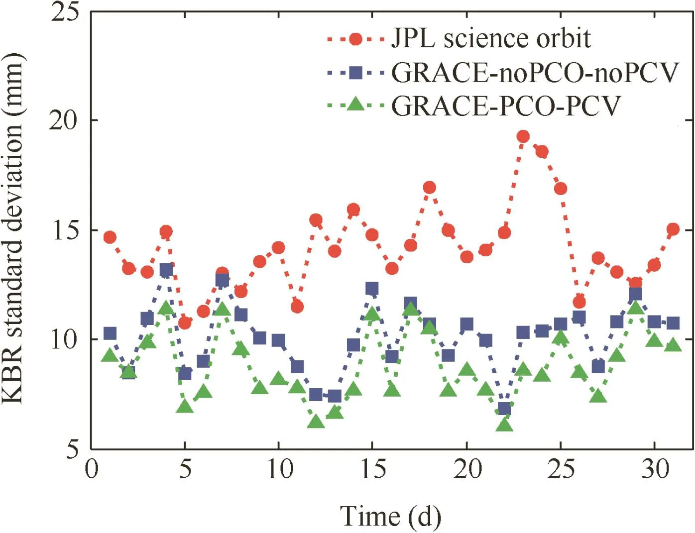
Fig.10 Daily standard deviations of KBR validation for GRACE satellites.
The average standard deviations of KBR comparison residuals are 10.1,8.8 and 14.2 mm.Compared to the relative positions obtained without PCO and PCV estimation,the average standard deviation of the relative positions obtained with PCO and PCV estimation is improved by 1.3 mm and is better than JPL precise science orbits.Considering that antenna PCO and PCV estimation could remove the phase errors of both GRACE satellites,the relative orbital position accuracy may be improved.
5.2.Orbit validation with SLR data
Another independent way for orbit validation is offered through SLR data.Statistics over the entire SLR data arcs for GRACE and Shiyan 3 satellites are displayed in Table 5.Typical results of an SLR comparison for orbit products with PCO and PCV estimation are shown in Fig.11.The mean value and the RMS of the SLR comparison residuals for each arc are calculated and used to compute statistics.At the International Laser Ranging Service(ILRS),no information is available for the Shiyan 3 satellite at present.Only the Chinese SLR stations(including Shanghai,Changchun,Beijing and Kunming)track this satellite.
Data sets used here are the same as those used in the PCV estimation.The results reveal that for the two GRACE satellites,the average RMS of orbit products obtained with PCO and PCV estimation is close to the JPL orbit products and better than that of orbit products obtained without PCO and PCV estimation.For the Shiyan 3 satellite,the average RMS of the orbit products obtained with PCO and PCV estimation is improved by 0.9 cm compared with the orbit products obtained without PCO and PCV estimation.Most of thesecontributions might come from the finding of a large PCO error value.In addition,the mean value of the Shiyan 3 satellite is significantly larger than that of GRACE satellites(see Table 5),which might be caused by the inaccurate a priori SLR antenna offset vector from COM,e.g.,COM error,because GPS antenna PCO vector from COM of the Shiyan 3 satellite is also inaccurate.
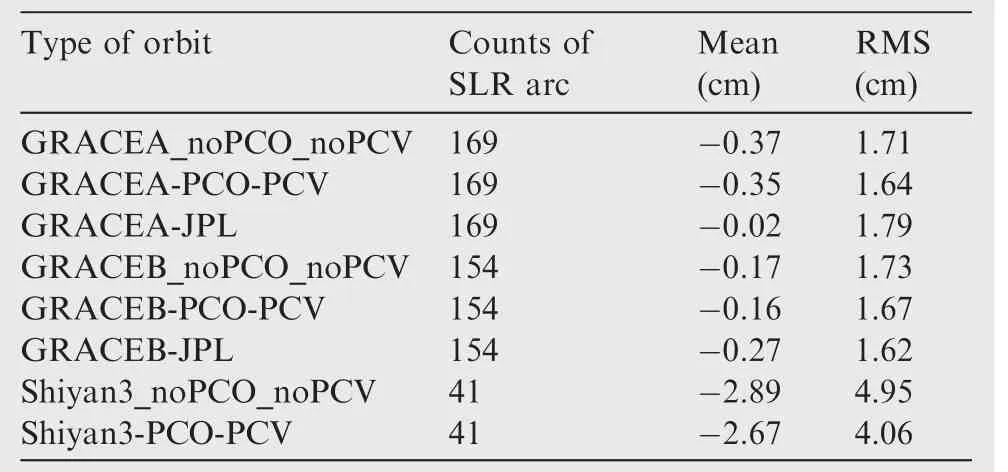
Table 5 SLR validation for different types of GRACE and Shiyan 3 orbit products.
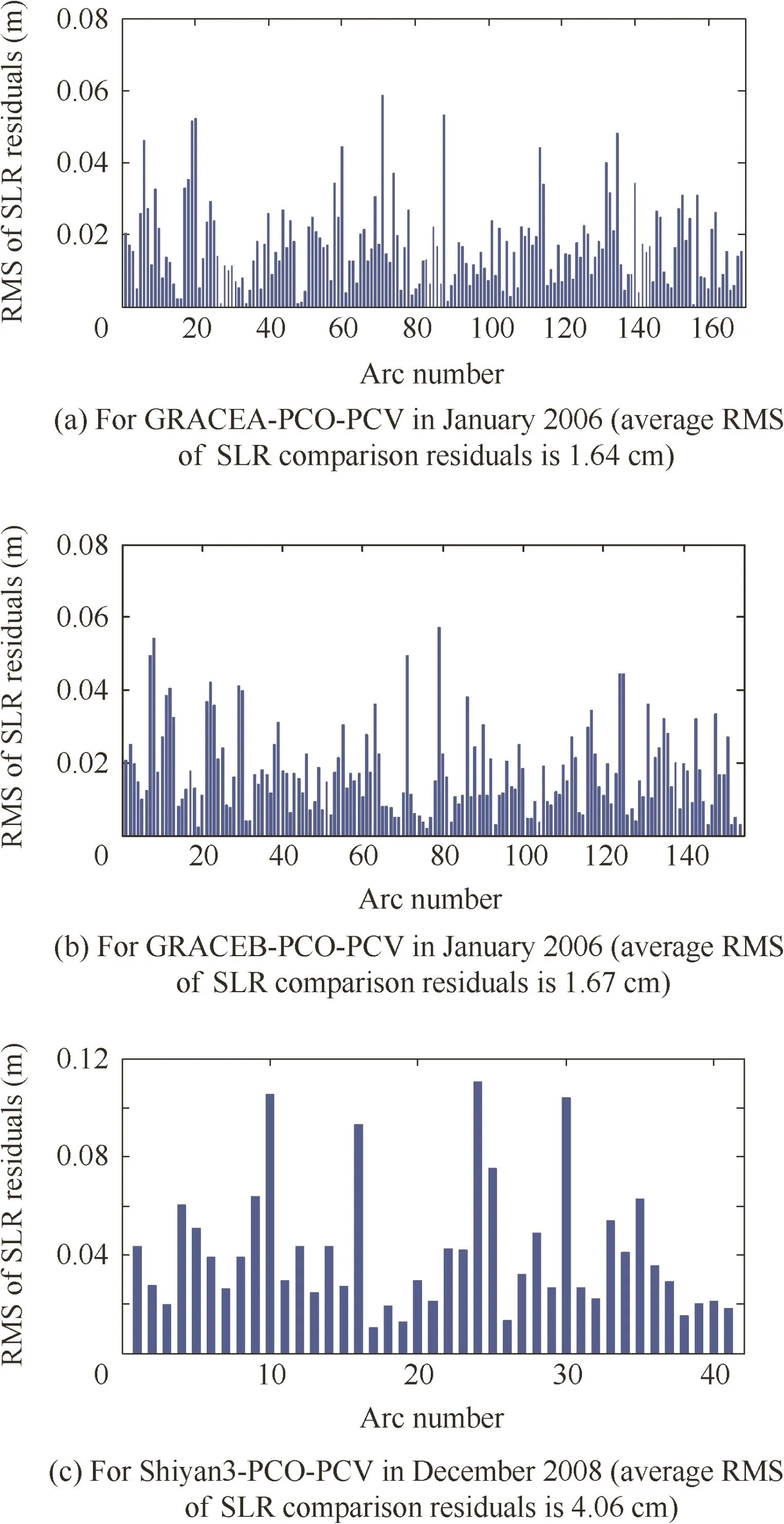
Fig.11 SLR comparison statistics for orbit products with PCO and PCV estimation of GRACE and Shiyan 3 satellites.
6.Conclusions
Antenna PCO and PCV error characteristics and influence principles on orbit determination are analyzed.The feasibility of PCO and PCV estimation and compensation in different directions is demonstrated by simulations and in-flight tests.Antenna PCO precise error estimation is feasible in the z-direction but is unstable in y-and x-directions.Most of the antenna PCVs can be effectively estimated,except for the y-direction.
Ground-based absolute calibration results from the anechoic chamber for Shiyan 3 choke ring antenna are not consistent with in-flight calibrations.A large and stable antenna PCO error in the z-direction is found on the Shiyan 3 satellite,of which the magnitude is up to 10.34 cm.The PCVs on the Shiyan 3 satellite are estimated,of which the magnitude is up to 3.0 cm,larger than those for GRACE satellites.
The significant improvement of orbits through PCO and PCV estimation and compensation can be confirmed by orbit validation with independent KBR and SLR measurements.For GRACE satellites,the average RMS of KBR residuals is improved from 1.01 cm to 0.88 cm and is better than JPL precise science orbits.For the Shiyan 3 satellite,the average RMS of SLR residuals is improved from 4.95 cm to 4.06 cm.The mean value is large,which might be caused by the inaccurate a priori COM.
Acknowledgements
The authors are grateful to Geo Forschungs Zentrum(GFZ)for providing data on GPS observation,attitude,KBR and precise science orbits of the GRACE mission.The authors also thank the Beijing Institute of Tracking and Telecommunication Technology for providing GPS observation,attitude and SLR data on Shiyan 3.
This study was co-supported by the National Natural Science Foundation of China(Nos.61370013 and 91438202)and the High Resolution Earth Observation System Major Special Project Youth Innovation Foundation of China (No.GFZX04060103).
1.Kang Z,Schwintzer P,Reigber CH,Zhu SY.Precise orbit determination for TOPEX/Poseidon using GPS-SST data.Adv Space Res 1995;16(12):59–62.
2.Ijssel J,Visser P,Patin˜o Rodriguez E.CHAMP precise orbit determination using GPS data.Adv Space Res 2003;31(8):1889–95.
3.Kang Z,Tapley B,Bettadpur S,Ries J,Nagel P,Pastor R.Precise orbit determination for the GRACE mission using only GPS data.J Geodesy 2006;80(6):322–31.
4.Haines B,Bar-Sever Y,Bertiger W,Desai S,Willis P.Onecentimeter orbit determination for Jason-1:New GPS-based strategies.Mar Geod 2004;27(1–2):299–318.
5.Ja¨ggi A,Hugentobler U,Bock H,Beutler G.Precise orbit determination for GRACE using undifferenced or doubly differenced GPS data.Adv Space Res 2007;39(10):1612–9.
6.Gu DF,Yi DY.Reduced dynamic orbit determination using differenced phase in adjacent epochs for spaceborne dual-frequency GPS.Chin J Aeronaut 2011;24(6):789–96.
7.Haines B.Space-based satellite antenna maps;impact of different satellite antenna maps on LEOamp;terrestrial results[Internet];2008 Jun[cited 2015 Nov].Available from:http://www.ngs.noaa.gov/IGSWorkshop2008/docs/Haines_IGS08.ppt.
8.Ja¨ggi A,Dach R,Montenbruck O,Hugentobler U,Bock H,Beutler G.Phase center modeling for LEO GPS receiver antennas and its impact on precise orbit determination.J Geodesy 2009;83:1145–62.
9.Luthcke SB,Zelensky NP,Rowlands DD,Lemoine FG,Williams TA.The 1-centimeter orbit:Jason-1 precision orbit determination using GPS,SLR,DORIS,and altimeter data.Mar Geod 2003;26(3):399–421.
10.Montenbruck O,Garcia-Fernandez M,Yoon Y,Scho¨n S,Ja¨ggi A.Antenna phase center calibration for precise positioning of LEO satellites.GPS Solut 2009;13(1):23–34.
11.Tu J,Gu DF,Wu Y,Yi DY.Phase residual estimations for PCVs of spaceborne GPS receiver antenna and their impacts on precise orbit determination of GRACE satellites.Chin J Aeronaut 2012;25(4):631–9.
12.Tu J,Gu DF,Wu Y,Yi DY,Wang JS.Phase error modeling and its impact on precise orbit determination of GRACE satellites.Math Probl Eng 2012;2012:589–97.
13.Ja¨ggi A,Montenbruck O,Moon Y,Wermuth M,Ko¨nig R,Michalak G,et al.Inter-agency comparison of TanDEM-X baseline solutions.Adv Space Res 2012;50(2):260–71.
14.Montenbruck O,Wermuth M,Kahle R.GPS based relative navigation for the TanDEM-X mission-first flight results.Navigation 2011;58(4):293–304.
15.Hwang C,Tseng TP,Lin TJ,Sˇvehla D,Schreiner B.Precise orbit determination for the FOR-MOSAT-3/COSMIC satellite mission using GPS.J Geodesy 2009;83(5):477–89.
16.Bock H,Ja¨ggi A,Meyer U,Dach R,Beutler G.Impact of GPS antenna phase center variations on precise orbits of the GOCE satellite.Adv Space Res 2011;47(11):1885–93.
17.Guo J,Zhao QL,Guo X,Liu XL,Liu JN,Zhou Q.Quality assessment of on board GPS receiver and its combination with DORIS and SLR for Haiyang 2A precise orbit determination.Sci Chin Earth Sci 2015;58(1):138–50.
18.Bilich A,Mader G.GNSS absolute antenna calibration at the national geodetic survey.Proceedings of the 23rd international technical meeting of the satellite division of the institute of navigation;2010 Sep 21–24;Portland;2010.
19.Go¨rres B,Campbell J,Becker M,Siemes M.Absolute calibration of GPS antennas:Laboratory results and comparison with field and robot techniques.GPS Solut 2006;10(2):136–45.
20.Schmid R,Dach R,Collilieux X,Ja¨ggi A,Schmitz M,Dilssner F.Absolute IGS antenna phase center model igs08.atx:Status and potential improvements.J Geodesy 2016;90(4):343–64.
21.Tapley B,Bettadpur S,Ries J,Watkins M.GRACE measurements of mass variability in the Earth system.Science 2004;305(5683):503–5.
22.Kroes R.Precise relative positioning of formation flying spacecraft using GPS[dissertation].Netherlands:Nederlandse Commissie voor Geodesie Netherlands Geodetic Commission Delft;2006.
23.Tang ZY,Wang L.Chuangxin-1-02 and Shiyan satellite 3 launched atop A LM-2D.Aerosp Chin 2008;9(4):23.
24.Tu J,Gu DF,Wu Y,Yi DY.Error modeling and analysis for InSAR spatial baseline determination of satellite formation flying.Math Probl Eng 2012;2012:346–60.
25.Bertiger W,Desai SD,Haines B,Harvey N,Moore AW,Owen S,et al.Single receiver phase ambiguity resolution with GPS data.J Geodesy 2010;84(5):327–37.
Gu Defengis an associate professor in National University of Defense Technology.He received his B.S.and Ph.D.degrees from National University of Defense Technology in 2003 and 2009,respectively.His research interests are modern statistical methods,measurement data processing and the precise orbit determination of satellites.
23 November 2015;revised 19 January 2016;accepted 20 June 2016
Available online 26 August 2016
GRACE;
Phase center offset;
Phase center variations;
Shiyan 3;
Spaceborne GPS
©2016 Chinese Society of Aeronautics and Astronautics.Production and hosting by Elsevier Ltd.This is an open access article under the CC BY-NC-ND license(http://creativecommons.org/licenses/by-nc-nd/4.0/).
*Corresponding author.Tel.:+86 731 84573246.
E-mail address:gudefeng@nudt.edu.cn(D.Gu).
Peer review under responsibility of Editorial Committee of CJA.
 CHINESE JOURNAL OF AERONAUTICS2016年5期
- CHINESE JOURNAL OF AERONAUTICS的其它文章
- Flapping wing micro-aerial-vehicle:Kinematics,membranes,and flapping mechanisms of ornithopter and insect flight
- A new non-linear vortex lattice method:Applications to wing aerodynamic optimizations
- Experimental study of flow field distribution over a generic cranked double delta wing
- Streamwise-body-force-model for rapid simulation combining internal and external flow fields
- An artificial neural network approach for aerodynamic performance retention in airframe noise reduction design of a 3D swept wing model
- effects of wing locations on wing rock induced by forebody vortices
