Description of a Propulsion Unit Used in Guiding a Walking Machine by Recognizing a Three-point Bordered Path
NÚÑEZ-ALTAMIRANO Diego A, Juárez-Campos Ignacio, Márquez-Pérez Lucia, and FLORES-DÍAZ Ociel
Description of a Propulsion Unit Used in Guiding a Walking Machine by Recognizing a Three-point Bordered Path
NÚÑEZ-ALTAMIRANO Diego A*, Juárez-Campos Ignacio, Márquez-Pérez Lucia, and FLORES-DÍAZ Ociel
School of Mechanical Engineering, Universidad Michoacana de San Nicolás de Hidalgo, Morelia, Michoacán, México
A reconfigurable propulsion unit based on the Peaucellier-Lipkin mechanism has the ability to describe exact straight or curved paths depending on the selected ratio between the lengths of two of its links. The Peaucellier-Lipkin mechanism with one degree of freedom is transformed into a more sophisticated parallel kinematic chain by including four more degrees of freedom. The resulting propulsion unit is able to adapt its kinematic structure and reach instant centers of rotation, in accordance with the presence of three points that border a geometric path. A laser sensor mounted on the body of the machine detects each point. Once the machine has detected the exact location of the border of the road, it walks along a curve parallel to that border. Although the proposed research describes only one propulsion unit or leg, the methodology can be applied to all the legs of the walking machine. The novel 5-DOF leg is able to reach different centers of rotation, providing either the concave or convex arcs that satisfy the basic principle of displacement of walking machines.
Propulsion unit, Peaucellier-Lipkin, walking machine, straight line mechanism.
1 Introduction
In 1864, Peaucellier C N, a French army officer, developed a very special mechanism by joining eight links to convert a circular motion into an exact linear one. Independently, the Russian mathematician Lipkin L[1–3]made the same mechanism and explained the ideas in more detail. Their separate but simultaneous work resulted in the mechanism’s being named the.
The PL mechanism has been studied in different postures and configurations[4]and it also has many inversions[5–6]. Other researchers have carried out systematic inquiries dealing with optimum dimensional synthesis[7–8], but most of those studies consider the basic PL mechanism without the addition of more degrees of freedom, even in relation to certain applications[9–10]. In addition, there is a remarkable lack of extensive information concerning the use of the PL mechanism as a robotic leg or propulsion unit.
Many robots and walking machines use different kinds of propulsion systems. Almost all of them use at least three degrees of freedom(DOFs) to move in a given space.
The walking machine mentioned in Refs. [11–12] has a reconfigurable system capable of transforming a quadruped chair into a biped walking machine, and is employed as an assistive walking robot[13]. Its main characteristic is the use of parallel propulsion mechanisms. When the chair is biped, each leg has six DOFs. In the quadruped mode, it has three DOFs per leg. The parallel mechanisms are lightweight and their payload capacity does not exceed 60 kg[14].
The hexapod robot, described in Ref. [15], is a walking machine made for nuclear plants in the event of a nuclear disaster. It uses parallel legs with 3 DOFs and can easily walk with more than 150 kg.
The propulsion mechanism in humanoid robots generally uses more DOFs because of their human-like movement. The HRP robot series described in Refs. [16–17] has at least six DOFs per leg. Asimo[18–19]is the most famous and complete biped robot, developed by the Honda Motor Corporation and has 6 DOFs per leg[20]. There are also biped robots with fewer DOFs, such as the one developed by Vázquez, et al[20]. This robot has two DOFs per leg and the authors study behavior on slippery surfaces.
BigDog[21]is a quadruped walking robot developed by Boston Dynamics. It is adapted to non-structured terrains and is used in military operations for carrying loads. It has four DOFs per propulsion unit driven by hydraulic actuators. The quadruped robot presented by WAIT, et al[22]has three DOFs per leg actuated by pneumatic motors and can be used in explorations.
The aim of this paper is to present a new propulsion unit based on the PL mechanism with five DOFs, three of which are used to configure the Reconfigurable Propulsion Unit (RPU) according to the path to be followed. The remaining DOFs are used to provide the step.
2 Propulsion Mechanism Description
The propulsion unit is based on the PL linkage. This mechanism has six rotational joints:,,,,and. Its eight links are,,,,,,and, and their lengths areL,L,L,L,L,L,LandL, respectively(see Fig. 1).

Fig. 1. Peaucellier-Lipkin mechanism and its nomenclature
Due to the fact that the Peaucellier-Lipkin linkage possesses one DOF, jointdescribes a straight line path when theθangle changes. Nevertheless, the 8-link mechanism must comply with the following relations:
2.1 Basic principle of displacement
In order to move in a three-dimensional space with the aid of its propulsion units, every walking machine is able to rotate on an axis passing through an instant center of rotation(). This is the Basic Principle of Displacement that each walking machine must comply with and it is illustrated in Fig. 2.

Fig. 2. Generic legged machine walking according to the Basic Principle of Displacement
Each propulsion unit links the main frame of the walking machine to the surrounding field. In this manner, one end of the propulsion unit is linked to the chassis while the other is either in contact with the surface or is levitating, according to the step-by-step walking process.
2.2 Modification of the Peaucellier-Lipkin mechanism
As described in Fig. 1, the center of joint F describes a straight line whenθvaries, according to the intrinsic behavior of the 1-DOF PL mechanism. This means that the basic PL linkage cannot meet the Basic Principle of Displacement.
The PL mechanism is highly rigid and very restrictive, so major changes must be made to accommodate or integrate new degrees of freedom for its conversion to and use as a robotic leg. To accomplish this, three major changes that involve the addition of four more degrees of freedom are necessary.
The first change exerted on the mechanism is derived from the integration of two degrees of freedom that allow lengthsLandLto vary according to the following three cases, each one providing a different path:
Case 1:L= L.describes a straight line, Fig. 1.
Case 2:L< L.describes a concave circular arc with respect to an observer placed at joint, Fig. 3.

Fig. 3. Concave circular arc
Case 3:L> L.describes a convex circular arc with respect to an observer placed at joint A, Fig. 4.

Fig. 4. Convex circular arc
With this in mind, the first modification of the basic PL mechanism involves the addition of two independent prismatic joints, one that exclusively modifies the length between jointsand. The other shortens or lengthens the distance between pointsand. This transformation enables the voluntary choice of any of the three different paths, letting the machine rotate on any instantaneous center of rotation, including the center found at infinity. The PL mechanism with only one DOF was modified to achieve a new one with three DOFs: one of them performs the rotation angleθ, and the other two are represented by linear actuators that modifyLand L.
Up to now, the propulsion unit is able to describe circular paths. Nevertheless, the arcs described by the feet of all the legs must have the same center of rotation. Thus, a rotational actuator must drive jointof each leg, providing the angleθ. The magnitude ofθdepends on the angle found between the straight segmentsand, Fig. 5. Due to the fact that pointmust describe an arc with a center of rotation(), segmentsandhave to be aligned. Therefore, the fourth DOF is represented by a rotational actuator that allows alignment to be achieved whenθ=0. Once those segments are aligned, the distances enclosed by jointsandand byandmust be calculated. In this manner, every leg is configured and has the capability to achieve the same.

Fig. 5. Angleθfound between segmentsand
In order to support the propulsion unit on the ground, one prismatic DOF must be added. This prismatic joint allows the support point located in the walking machine foot at joint F to be raised or lowered. This variable is namedL, Fig. 6.

Fig. 6. Location of the five DOFs on the new RPU
The above description introduces a new 5-DOF RPU, satisfying the Basic Principal of Displacement. The five DOFs are summarized in Fig. 6 and described in Table 1.

Table 1. Joint descriptions

Fig. 7. Linear actuator, placed at point F, modifies the lengthLto raise or lower the foot, according to the road
The design of the novel RPU is illustrated in Fig. 8. Its complete description is published in the patent application document, number MX/a/2014/008184[23].

Fig. 8. Novel 5-DOF RPU
2.3 Operation of the reconfigurable propulsion unit
The propulsion unit has five DOFs, three of which are used to reconfigure it in relation to the required path, as follows: (1) a prismatic DOF modifiesL, (2) a prismatic DOF modifiesL, and (3) a revolute joint articulates link, changingθto align the,and. After the reconfiguration, the propulsion unit uses only two DOFs to describe any spatial path. They are (4) the revolute joint that changes angleθto rotate link BC to produce a step, and (5) the prismatic joint that allows the walking machine foot to be raised or lowered, changing the lengthL.
3 Kinematics
This section describes the direct and inverse kinematics of the RPU. Direct kinematics explain the position of the foot as a function of anglesθandθ, and the link lengthsL,LandL. Inverse kinematics determineθandθ, and the link lengthsL,LandLin terms of the center of rotation() and the position of the foot, which are needed to describe paths that are parallel to the contour of the road. It involves recognizing the position of three points placed at the line bordering the road.
3.1 Direct kinematics
In order to describe the center of joint F, it is necessary to find its position as a function of θ,LandL, considering the constant lengthsL,L,L,L,LandL, and meeting the following conditions:
The positions of the centers of joints,,,,andare described, with respect to {N} in Eqs. (3)-(13), according to Fig. 9. For the purposes of the kinematic analysis dealing with the novel RPU, the spatial description between two frames,andmust be established, as described in Eq. (1), assuming that {} is located on the ground surface and {} lies on the plane where points,,,,andare located, considering that the RPU is a planar mechanism. The origin of {} is located at the distanceLfrom {} in the direction given by.

(2)
The center of joint, described byin Eq. (3), is the origin of the local frame {}, which is used to describe the planar mechanism.

The centers of jointsand, defined by,,,and, are described by
, (4)
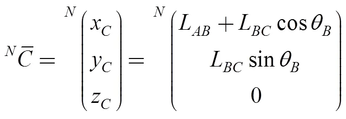
Fig. 9. Upper view of the simplified mechanical system, frames {} and {},and some important angles
In order to describe point, defined byin Eq. (9), it is necessary to determine α,Land, which are described by Eqs. (6)-(8):

, (7)
, (8)

Finally, pointsand, defined byandin Eqs. (12) and (13), make use ofandL, which are presented in Eqs. (10) and (11):
, (10)

, (12)
. (13)
It is important to note that,,,,and, are functions ofθ,LandL. When,,,,andare changed with respect to {M}, the joint variableθappears according to Eq. (1).
Due to the fact that the propulsion unit is basically a positioning device, the foot of the unit is able to move vertically, driven by a prismatic joint. In order to command the walking machine to move its foot, the joint variableLmust be controlled. Therefore, the foot is described by. WhenL= L, then the foot is placed on the ground, indicating a support condition. WhenL< L, the leg is said to be in a transfer condition.
3.2 Path description
All walking machines move through a three-dimensional space using their propulsion units. In order to explain the functionality of the new RPU, a road with reflecting laser devices along the left and right contours was used, Fig. 10. This road has straight and curved sections. Curved paths are assumed to be composed of a succession of concave and convex circular arcs.
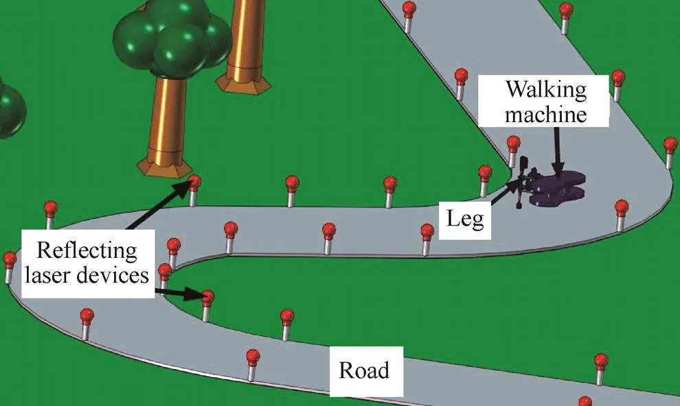
Fig. 10. Road with reflecting laser devices on its contour
The walking machine recognizes the route and controls its travel with the aid of the position of three of the abovementioned reflecting laser devices. These three devices can be placed at the left or right contours of the road. The three recognized points let the walking machine find the curvature of the road through an emitting-receiving laser sensor, providing the exact position of the. Once this point is determined, the joint variablesθ,LandLare calculated. They are necessary for reconfiguring every RPU so that the walking machine can then follow a path that is parallel to the contour of the road.
Regardless of the number of legs mounted on the walking machine, the control of every RPU is similar, so the kinematic analysis of only one of them is explained herein. However, it is important to note that when the CR is to the right of the walking machine, the feet of the right propulsion units follow convex arcs, whereas the feet of the left ones follow concave arcs. A similar process occurs when the CR is situated to the left side of the walking machine.
3.3 Inverse kinematics
In order to describe a path parallel to the road’s contour by means of the foot of the RPU,LandLhave to be found based on the three recognized points.
It is important to remember thatL,L,L,L,LandLare constants andLandLvary with the restriction given by

3.3.1 Description of the center of rotation(CR)
The coordinates of the three pointsP, PandP, on the road’s contour with respect to the frame {} are described by vectors presented in Eq. (15), and shown in Fig. 11.

Fig. 11. Coordinates of the three points on the road’s contour
The middle points of the straight lines12and23defined among points described by Eq. (15) are presented in Eqs. (16) and (17). It has been assumed that the ground is a flat and horizontal surface, meaning that12and3are equal to zero

. (17)
The slopes of the straight lines12and23are calculated by Eqs. (18) and (19), using the coordinates given by (15):

. (19)
The perpendicular slopes are determined by Eqs. (20) and (21):

. (21)
The bisector Eqs. (22) and (23) of lines12and23were generated by means of the perpendicular slopes, Eqs. (20) and (21), and the middle points Eqs. (16) and (17):

. (23)
Thecoordinates were obtained through the use of Eqs. (24) and (25), by means of Eqs. (22) and (23), which were solved simultaneously:

. (25)
Once the description of theis known, Eq. (26), with respect to the frame {},θis calculated using the reference angle, presented in (27):

(27)
Whenx<,θis obtained by Eq. (28). This is illustrated in Fig. 12.

(28)
Fig. 12. Unit oriented according to the, case 2
Whenx>,θis obtained by

This can be seen in Fig. 13. In order to align the,, and, the rotary actuator is placed atand modifiesθ.
Fig. 13. Unit oriented according to the, case 2
3.3.2 Postures for concave arcs
Whenx<0, pointwill describe a concave path with respect to the origin of {}. Nevertheless, the lengths of linksandmust be found, described by case 2,L< L. It is assumed that the sum of both lengths remains constant, and is defined by Eq. (14).
The propulsion unit has two particular postures. The first one is described whenθ=0, as shown in Fig. 12. The second one, presented in Fig. 14, corresponds toθ> 0, and the variables are distinguished by an apostrophe.

Fig. 14. Angle and length descriptions whenθ> 0, case 2
In order to describe the constant lengthk, considering the case when θ=0, Eqs. (8) and (11) are modified. The results are shown in (30) and (31):

. (31)
In order to describe pointwhenθ> 0, it is necessary to propose a permissible1, see Eq. (32):

where
, (33)

, (35)
where

, (37)

Fig. 15. Linksand, case 2

, (40)
where

. (42)
In Fig. 16, the RPU is observed with three points located along the contour of the road where theis found.

Fig. 16. Location of the center of rotation, case 2
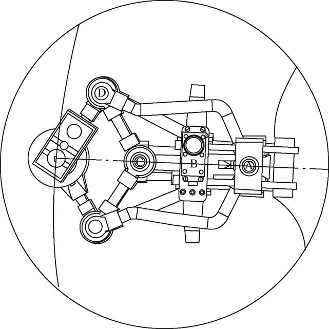
Fig. 17. Details of the RPU for case 2
3.3.3 Postures for convex arcs
The convex arc settings are described in case 3, whenL> Landx>0. Eqs. (14), (30) and (31) are used and were applied in case 2, because the posture corresponds to that whenθ= 0.
In order to find the propulsion unit configuration, theis needed and calculated with the aid of Eqs. (24) and (25). Consideringθ> 0, the posture terms are distinguished by a double apostrophe. To describe point, it is necessary to propose a permissible angle2, as shown in Fig. 18, wherek''is the distance betweenand.

where
, (44)

Fig. 18. Description of angles and lengths whenθ> 0, case 3
Variablek''is calculated by means of Eq. (46):

where
. (47)

. (49)
Fig. 19. Linksand, corresponding to case 3
When Eqs. (48) and (49) are simultaneously solved,andare found and described in Eqs. (50) and (51):
, (51)
where
In order to find the configuration of the propulsion unit corresponding to case 3, three points on the contour of the road are required, as shown in Fig. 20.
Fig. 20. Location of the center of rotation, case3
In Fig. 21, a detailed view of the RPU is observed describing a convex path.
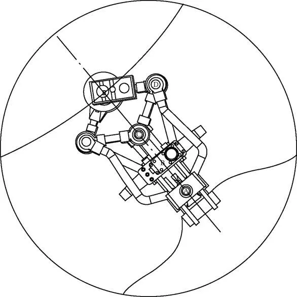
Fig. 21. Detail of the novel RPU corresponding to case 3
3.3.4 Postures for straight lines
When theis located at infinity, the path followed by the propulsion unit is a straight line. Consequently,LandLmust be equal, as described in Eq. (53):

4 Conclusions
(1) The novel robotic leg presented herein is based on the Peaucellier-Lipkin mechanism, which is well known as the. Due to the fact that the basic Peaucellier-Lipkin mechanism has one DOF and traces straight lines, it was necessary to make important changes, which were obtained by the addition of four more degrees of freedom. In this manner, the novel 5-DOF leg is able to reach different centers of rotations, providing concave or convex arcs, depending on what is needed to satisfy the basic principle of displacement of walking machines.
(2) Three DOFs are used to adapt or configure the leg in terms of a specific center of rotation. The remaining DOFs help to transport its foot, depending on the support or transfer conditions.
(3) The RPU is capable of generating paths in a given space with only two DOFs, once it is reconfigured. The walking robots with traditional propulsion units require at least three DOFs per leg.
(4) The walking machine that uses the RPU with the characteristics described in this paper can move on structured and non-structured terrain.
(5) The RPU adopts a specific configuration in relation to three points located along the contour of the road and the walking machine moves parallel to it.
[1] Dijksman E. On the History of focal mechanisms and their derivatives[C]//Cassino, Italy, May 12–15, 2004.
[2] Luquin F. Steam engines, mechanisms and P. L. Chebyshev[C]//Bilbao, Spain. February 23, 2005.
[3] Tarabarin V, Tarabarina Z, Chirkina D. Designing, analysis and computer modeling of straight-line mechanisms[C]//, Amsterdam , 2012.
[4] Kempe A B. How to draw a straight line[M]. London: Nature Series (Publishers), 1877: 86–89.
[5] Dijksman E A. A Fourfold generalization of peaucellier’s inversion cell[J]., 31(4), 1996: 407–420.
[6] Dijksman E a. A way to generalize Peaucellier’s inversor[C]//Vol. I, Paper 10, SYROM ‘93, Bucurqti, Romsnia, June 1993: 73–82.
[7] Bukckley J. An Investigation into straight-line mechanisms: optimizing the peaucellier mechanism[C]//, New York, USA, 2011.
[8] HEO J C, YOON G H. Size and configuration syntheses of rigid-link mechanisms with multiple rotary actuators using the constraint force design method[J]., 2013, 64: 18–38.
[9] Seifabadi R, Iordachita I, Fichtinger G. Design of a teleoperated needle steering system for MRI-guided prostate interventions[C]//, Roma, Italy. June 24–27, 2012.
[10] CHALFIN L. Phonograph pickup arm, US2977126 [P/OL]. (1956- 03-26)[2015-01-11]. http://www.google.co.ve/patents/US2977126.
[11] ZHENGYAN Q, HONGBO W, ZHEN H, et al. Kinematics of a quadruped/biped reconfigurable walking robot with parallel leg mechanisms[C]//, DAI J S, ZOPPI M, KONG X, eds, Jun 2009: 558–564.
[12] DEJUN M, ERJUAN L, XIAO L, et al. Gait planning and simulation of parallel walking robot[C]//August 4–7, 2010Xi’an, China, 2010: 1543–1549
[13] Ling-Feng S, Hong-Bo W, Dian-Fan Z, et. al. Application of parallel mechanism in varistructured quadruped/biped human- carrying walking chair robot[J]., 2013, 10(5): 447–454.
[14] Hashimoto K, Sugahara Y, Sunazuka H, et al. Human-carrying biped walking vehicle[C]//, Advanced Research Institute for Science and Engineering, Waseda University, April 30, 2008.
[15] Yang P, Feng G. Payload capability analysis of a new kind of parallel leg hexapod walking robot[C]//Luoyang, China, IEEE, September 25–27, 2013:541–544.
[16] Jun-Ho O, HANSON D, WON-SUP K, et al. Design of Android type humanoid robot Albert HUBO[C]//, Beijing, China, October 9–15, 2006: 1428–1433.
[17] Ill-Woo P, Jung-Yup K, Jungho L, et al. Development of biped humanoid robots at the Humanoid Robot Research Center, KAIST[M]//,HACKEL M, ed. ISBN 978-3-902613-07-3, Itech, Vienna, Austria, June 2007: 43–64.
[18] Hirose M, Haikawa Y, Takenaka T, et al. Development of humanoid robot ASIMO[C]//,, Maui, USA, 2001.
[19] Hirose M, Ogawa K. Honda humanoid robots development[J].2007(365): 11–19.
[20] Vázquez J, Velasco-Villa M. Experimental estimation of slipping in the supporting point of a biped robot[J]., 2013, 11(June): 348–359.
[21] Playter R, Buehler M, Raibert M.[M]. Bellingham: International Society for Optical Engineering, 2006: 1–6.
[22] Wait K, Goldfarb M. A pneumatically actuated quadrupedal walking robot[J]., 2014, 19(1): 339– 347.
[23] Juárez-Campos I, Núñez-Altamirano D, MÁRQUEZ- PÉREZ L, et al.Reconfigurable propulsion unit for walking machines: MX2014008184(A)[P/OL]. (2015-12-28)[2016-04-03]. http://worldwide.espacenet.com/searchResults?bookmarkedResults=true&submitted=true&DB=EPODOC&locale=es_lp&AP=MX20140008184&sf=a&&PGS=15&CY=lp&LG=es&ST=advanced.
Biographical notes
NÚÑEZ ALTAMIRANO Diego A, born in 1985, is currently a PhD candidate at. He received his master’s degree from the, in 2008. His research interests include walking machine systems and robotics.
Tel: +-52-4432362518; E-mail: diegocuyo@hotmail.com
JUAREZ CAMPOS Ignacio, born in 1966, is currently a professor at. He received his PhD degree from, in 2002. His research interests include mechatronics engineering, walking machines and robotics.
Tel: +52-4431257868; E-mail: al13507237@unadmexico.mx
MARQUEZ-PÉREZ Lucia, born in 1974, is currently a professor at. She received her PhD degree from, in 2011. Her research interests include biomedic engineering, tissue engineering, biomaterials, walking machines and robotics.
Tel: +52-4431409385; E-mail: lucia3366@gmail.com
FLORES-DÍAZ Ociel, born in 1977, received his PhD degree from, in 2013. His research interests include dynamics for machines and robots.
E-mail: ocielfd@gmail.com
Received March 19, 2015; revised May 13, 2016; accepted May 18, 2016
Supported by Postgraduate Department of School of Mechanical Engineering, Universidad Michoacana de San Nicolás de Hidalgo, Francisco J. Múgica S/N Ciudad Universitaria, C.P. 58030, Morelia, Michoacán, México
© Chinese Mechanical Engineering Society and Springer-Verlag Berlin Heidelberg 2016
Appendix
Nomenclatures
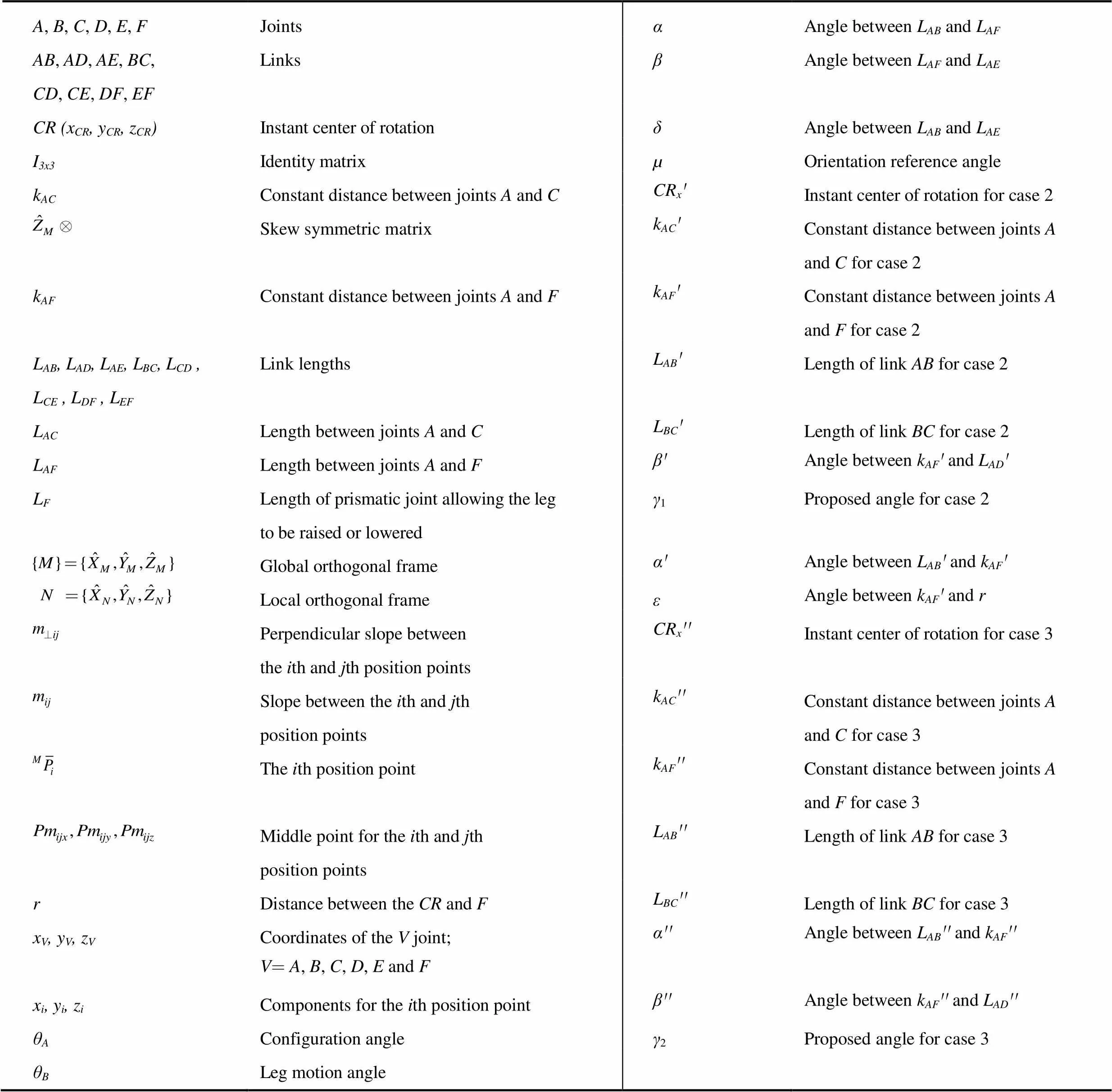
A, B, C, D, E, FJointsαAngle between LAB and LAF AB, AD, AE, BC,CD, CE, DF, EFLinksβAngle between LAF and LAE CR (xCR, yCR, zCR)Instant center of rotationδAngle between LAB and LAE I3x3Identity matrixµOrientation reference angle kACConstant distance between joints A and CCRx'Instant center of rotation for case 2 Skew symmetric matrixkAC'Constant distance between joints A and Cfor case 2 kAFConstant distance between joints A and FkAF'Constant distance between joints A and Ffor case 2 LAB, LAD, LAE, LBC, LCD , LCE , LDF , LEFLink lengthsLAB'Length of link AB for case 2 LACLength between joints A and CLBC'Length of link BC for case 2 LAFLength between joints A and Fβ'Angle between kAF' and LAD' LFLength of prismatic joint allowing the leg to be raised or loweredγ1Proposed angle for case 2 Global orthogonal frame α'Angle between LAB' and kAF' Local orthogonal frameεAngle between kAF'and r Perpendicular slope betweenthe ith and jth position pointsCRx''Instant center of rotation for case 3 Slope between the ith and jth position points kAC''Constant distance between joints A and Cfor case 3 The ith position point kAF''Constant distance between joints Aand Ffor case 3 Middle point for the ith and jth position pointsLAB''Length of link AB for case 3 rDistance between the CR and FLBC''Length of link BC for case 3 xV, yV, zVCoordinates of the V joint; V=A, B, C, D, E and Fα''Angle between LAB''and kAF'' xi, yi, ziComponents for the ith position pointβ''Angle between kAF''and LAD'' θAConfiguration angleγ2Proposed angle for case 3 θBLeg motion angle
10.3901/CJME.2016.0518.068, available online at www.springerlink.com; www.cjmenet.com
E-mail: diegocuyo@hotmail.com
 Chinese Journal of Mechanical Engineering2016年6期
- Chinese Journal of Mechanical Engineering的其它文章
- Digital Relief Generation from 3D Models
