Vorticity Dynamics and Control of Self-PropelledFlying of a Three-Dimensional Bird
Linlin Zhu, Hui Guan, Chuijie Wu,*
(1. State Key Laboratory of Structural Analysis for Industrial Equipment, Dalian Liaoning 116024, China 2. Dalian University of Technology, Dalian Liaoning 116024, China 3. PLA University of Science and Technology, Nanjing Jiangsu 211101, China)
Vorticity Dynamics and Control of Self-PropelledFlying of a Three-Dimensional Bird
Linlin Zhu1,2, Hui Guan3, Chuijie Wu1,2,*
(1. State Key Laboratory of Structural Analysis for Industrial Equipment, Dalian Liaoning 116024, China 2. Dalian University of Technology, Dalian Liaoning 116024, China 3. PLA University of Science and Technology, Nanjing Jiangsu 211101, China)
Birds are propelled and lifted by wings’ flapping and rotating motion. In this study, the rotation amplitude and rotation time interval of wings were studied, the self-propelled flying motion of a three-dimentional(3D) bionic bird in a viscous flow is investigated numerically with a 3D computational fluid dynamics (CFD) package. The package includes the immersed boundary method (IBM), the volume of fluid (VOF) method, the adaptive multi-grid finite volume method, and the swimming and flying control strategy. It is suggested that the bird can fly faster forward or upward with an appropriate rotation amplitude and rotation time interval.
Self-propelled, Bird flying, Numerical simulation, Three-dimensional, Rotation angle
0 Introduction
Flight has fascinated humans for many centuries [1]. Many animals have better movement per-formance than man-made vehicles, they can reduce drag force, suppress the turbulence and produce much more lift than our understanding. Birds are one of the efficient flyers in the nature, and their flapping flight is more complicated and efficient than the flight with fixed wings, as its dynamics is determined not only by its deformation but also by its wing motion aspects, such as flapping, rotation, and the specific relationship between flapping and rotation. Understanding of the dynamic interaction between the fluid and the wing may lead to a better
micro air vehicles (MAV) design[1].
Flapping flight has attracted global attention recently, and much work has been done using both experimental and computational methods (e.g. Ellington et al.
[2], Dickinson et al.
[3], Sane and Dickinson [4], Liu et al.
[5], Sun and Tang [6, 7], Usherwood and Ellington [8], Wang et al.
[9]), also a considerable understanding of the aerodynamic force generation mechanism has been achieved. However, in most of these studies, the flight was fixed and the body couldn’t move or rotate freely when is subjected to the action of the pressure, the viscous force and the gravity. Will the flapping flight with unfixed body and freely wings
be the same? Study of a 3D bird’s self-propelled flying is more difficult but more similar to a real flyer in the nature.

In the present study, numerical simulation of 3D bionic bird is used as a convenient tool. This is achieved by a CFD software package for 3D moving boundary problems, which combines the adaptive mesh refinement method, the immersed boundary method (IBM) and the volume of fluid (VOF) method, which is described in[12,13].
1 Numerical Approaches
In this study, the incompressible unsteady Navier-Stokes equations are solved using the finite volume method. The Cartesian adaptive mesh refinement technique is used to compute the flows with minimum overload. The computational domain is spatially discretized by a cubic finite volumes organized hierarchically as an octree. The projection and the multi-levels methods are used to solve the Poisson equation of pressure. The convective terms are discretized by the second order Godunov type scheme. The diffusion terms are discretized with the implicit Crank-Nicolson scheme, which can eliminate the viscous stability constraint. The details of the numerical algorithms refer to [14].
The study of bird self-propelled flying is a moving boundaries problem involving complex geometry. The computing methods of moving boundaries problem are usually classified into the body-fitted moving mesh method and IBM for computational fluid dynamics. The boundary conditions can be simply and accurately set using body-fitted moving mesh method, but the grid generation is a difficult and time-consuming task. IBM requires significantly less computation than other methods without sacrificing the accuracy. In the present study, moving boundaries are treated with ghost-cell IBM, which employs discrete forcing where the forcing is either implicitly or explicitly applied to the discretized Navier-Stokes equations. The technique of adaptive multi-grids is used and the adaptive refinement criteria are both vorticity andT, whereTis a tracer of VOF. This ensures that the meshes intersecting with the moving body boundaries are the finest and accurate representation of moving boundaries is achieved [3].
2 Motion Equations and Flying Parameters
2.1 Motion Equations
The dynamics governing equations for a 3D self-propelled bionic bird are
(1)
(2)
wheremis the mass of the bionic bird,uis the translational velocity vector,Mis the moment andLis the moment of momentum,Iis the inertia tensor andΩis the rotation angular velocity vector.Fis the external force acting on the bird, including external forces due to local flow structures and the gravity acting on the bird, the external force due to local flow structures is defined by
Ff=-∫∂B(-pn+μω×n)ds
(3)
where∂Bis the surface of the 3D bionic bird,nis the unit normal vector pointing out of the surface;μandωare the shear viscosity and vorticity, respectively. Equation (3) is a classical force formula derived directly from the momentum balance.
2.2 Flapping Rule and Kinematic Parameters
In this paper, the computational domain is 4×3×3(length×width×height), the dimensionless bird’s wingspan is 0.94, the density ratio of bird body to air is 20, the gravitational acceleration is 9.8, and the kinematics viscosity coefficient of the fluid isν=15.7×10⁻⁶.
The bird body consists of four parts, the body trunk, the tail and a pair of flapping wings, which is shown in Figure 1(a) and (b). Figure 2 shows the 3D structures due to bird’s self-propelled flying, which is observed from the side and above.
The flapping motion of the wings contains two steps, rotation and flapping. The first step, both wings rotate along theyaxis (see Figure 1(c)), the rotation angleα2(t) is shown in Equation (5). The second step, both wings rotate along two straight lines parallel to thexaxis, the two lines contain the points (xp,yp,zp) and (xp, -yp,zp), respectively, which are intersection point of the bird body and each of the wings (see Figure 1(b)); the flapping angle of the right wing is always reversed to the left one. In this study, the flapping angle of the left wingα1(t) is defined as the major one, which is shown in Equation (4).
In the study, the bird body coordinates (xl,yl,zl) and the global coordinates (x,y,z) are used, which can be converted to each other. In the bird body coordinate system, the flapping angleα1(t) and the rotation angleα2(t) in the first period can be written as:
(4)
α2(t)=
(5)
wheretis the time,αmandαnare the flapping amplitude and the rotation amplitude of the wings, respectively;Tis the flapping period,T1is the total rotation time interval of the wings in one flapping period.
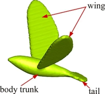
(a) Side view of the bird body
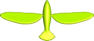
(b) Top view of the bird body
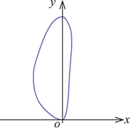
(c) Outline of the wingFig.1 3D profile of the bird body.
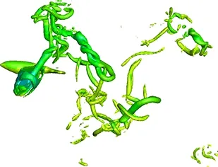
(a) Side view of the 3D vortex structure
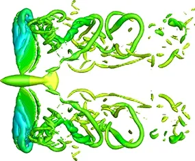
(b) Top view of the 3D vortex structure
Fig.2 3D vortex structure around the flying bird.
The Equation (4) is presented by the red real line with “▲” in Figure 3(a), which is part of a cosine function with the maximum valueαmand the minimum value -αm. The Equation (5) is presented by the blue real line with “○” in Figure 3(a), more details are presented in Figure 3(b). The first equation is presented by the left black dashed line, which is a part of the sinusoidal function, where 0 andαnare the minimum and the maximum value of the line, andT1/4 is the maximumxaxis value. The second equation is presented by the left red real line, which is a straight line with a constant valueαn. The third equation is presented by the dark blue dash dot line, which is a part of a sinusoidal function, whereαnand -αnare the maximum and the minimum values of the line. The forth equation is presented by the right red real line, which is a straight line with a constant value -αn. The fifth equation is presented by the right black dashed line, which is a part of the sinusoidal function, where -αnand 0 are the minimum and the maximum value of the line. In Fig.3,αm=40°,αn=35°,T= 0.02,T1= 0.4T= 0.008.
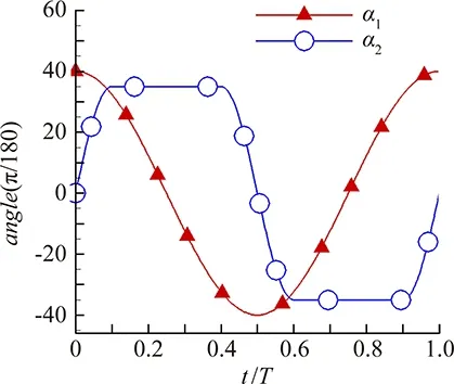
(a) Flapping angle and rotation angle
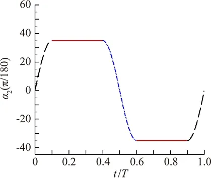
(b) Rotation angleFig.3 Angles of the flapping wings in one period.
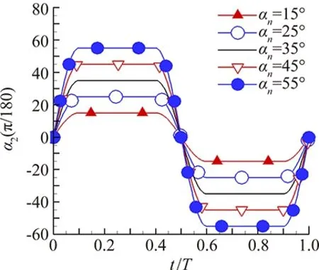
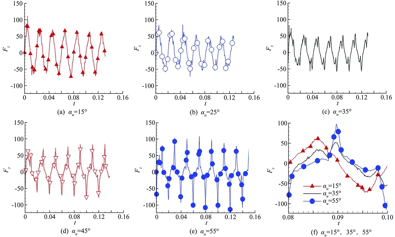
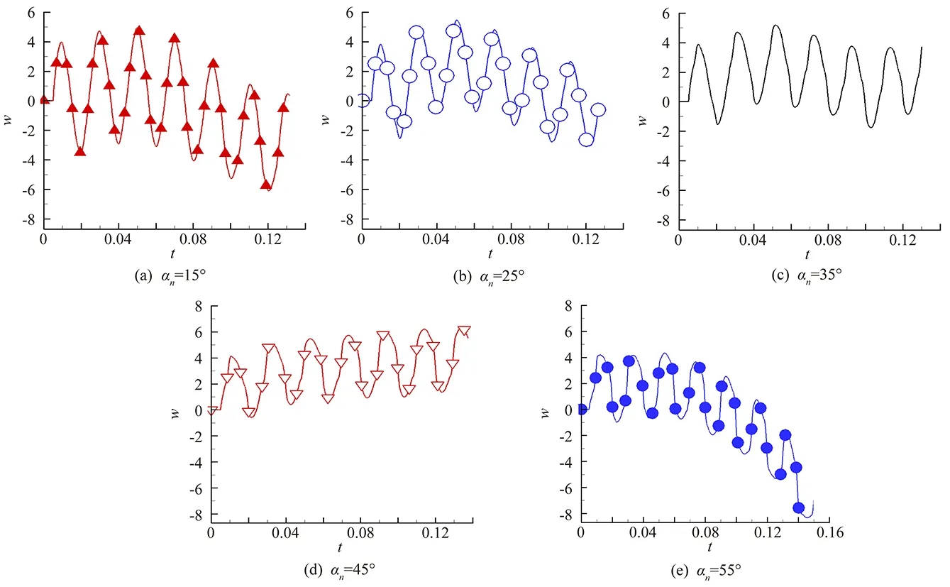
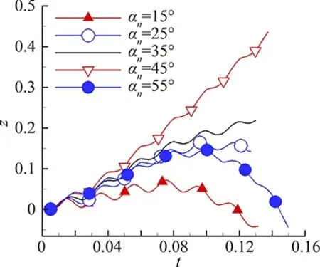
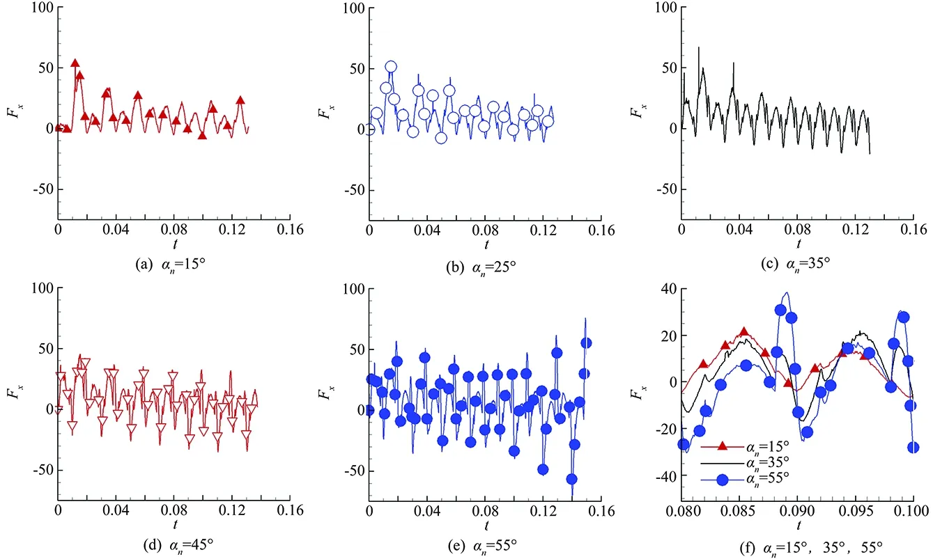
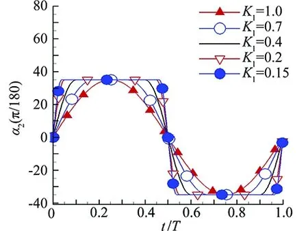
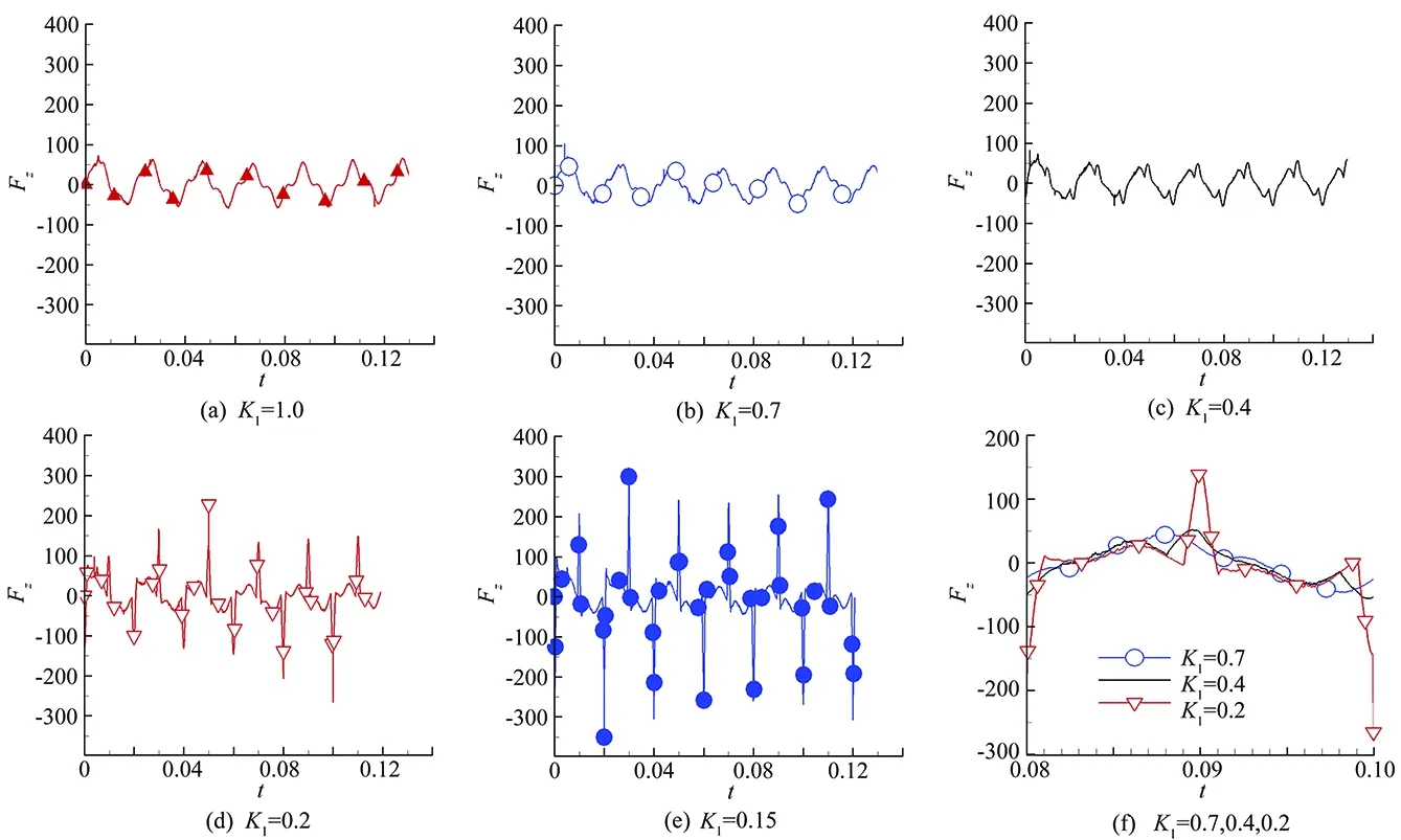
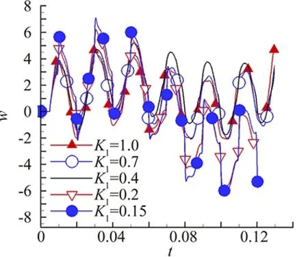
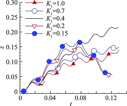
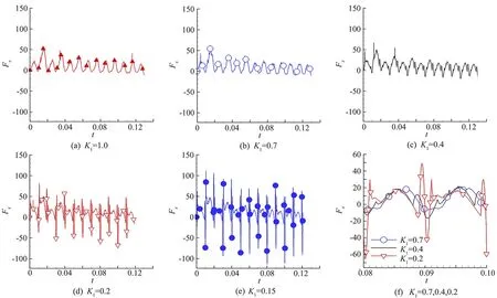
The flapping motion of the wings contains both downstroke and upstroke in one period. Downstroke consists of four parts: when 0≤t Especially, whenT1=T, both downstroke and upstroke only consist the first and the forth parts, which is shown in Figure 14 withK1= 1.0. 2.3 Boundary and Initial Conditions All boundaries of the computational region are set to be nonslip boundary conditions, i.e. ub=vb=wb= 0. Thus, the computational region is like a flume without inflow nor outflow. The bionic bird is stationary at the beginning, so the initial condition is u=v=w= 0. The immersed boundary conditions on the bird’s body surface are as follows. The body surface velocity of every point consists of the following three components. (1)The velocityV0arose from the aerodynamic force. (2)The linear velocityVrarose from the rotation. (3)The velocityVfarose from the flapping motion, which contains flapping and rotation. In the global coordinate system, the velocity of the bird surface generated by the flapping wings is: In this study, the body trunk, the tail and two flapping wings are rigid body, respectively. At the beginning, the body trunk is fixed, we control the wings’ flapping and rotation, which is shown in Figure 3, so we can calculate the velocity of every point on the bird’s body surface, which we used as immersed boundary condition; then we can use the Navier-Stokes solver to compute the viscous force and the pressure force with the immersed boundary condition and the computational region boundary condition. Base on all above, the resultant force and moments due to the gravity, viscous force and pressure force can be achieved, so do the translation velocity and rotation angular velocity. In the end, we achieve the new flight position (at the beginning, the flight position is fixed; and after a critical time, which isT/4 in this study, the position is changed) including the translation and rotation from the last position. The next step is to use this translation velocity and rotation angular velocity getting the velocity of every point on the bird’s body surface as new immersed boundary condition. 3.1 Different Rotation Amplitude Compared In this present study, five rotation amplitudes, i. e.,αn=15°, 25°, 35°, 45°, 55° were studied (Figure 4). The flapping periodT=0.02. In Figure 4, we found that, whent/T=0, 0.5, 1.0, the rotation angleα2changes dramatically with the increase of the rotation amplitudeαn, so the velocity arisen from the wings’ rotation become larger. Whent/T=0, 1.0, the flapping wings are at the beginning of downstroke; and whent/T=0.5, the flapping wings are at the end of downstroke. Fig.4 Different rotation amplitudes. Figure 5 shows the pressure distribution on the upper surface at the beginning of downstroke, the pressure in the region near the trailing edge on the upper surface is increased with the increase ofαn. Figure 6 shows the pressure distribution on the lower surface at the beginning of downstroke, the pressure in the region near the trailing edge on the lower surface is decreased with the increase ofαn. So the downward pressure on the wings’ surface is increased and the lift is decreased with the increase ofαnat the beginning of downstroke, which is shown in Figure 9. Figure 7 shows the pressure distribution on the upper surface at the end of downstroke, the pressure in the region near the trailing edge on the upper surface is decreased with the increase ofαn. Figure 8 shows the pressure distribution on the lower surface at the end of downstroke, the pressure in the region near the trailing edge on the lower surface is increased with the increase ofαn. So the upward pressure on the wings’ surface is increased and the lift is increased with the increase ofαnat the end of downstroke, which is shown in Figure 9. (a) αn = 15°(b) αn=25°(c) αn = 35°(d) αn=45°(e) αn=55°Fig.5 Pressure distribution on the upper surface when t = 0.04. (a) αn = 15°(b) αn=25°(c) αn = 35°(d) αn=45°(e) αn=55°Fig.6 Pressure distribution on the lower surface when t = 0.04. (a) αn = 15°(b) αn=25°(c) αn = 35°(d) αn=45°(e) αn=55°Fig.7 Pressure distribution on the upper surface when t = 0.05. (a) αn = 15°(b) αn=25°(c) αn = 35°(d) αn=45°(e) αn=55°Fig.8 Pressure distribution on the lower surface when t = 0.05. Fig.9 Lift of different rotation amplitudes. Fig.10 Velocity w of different rotation amplitudes. Figures 9(a)-(e) shows that the liftFzchanges periodically, here the period isT. One can see that, at the beginning and the end of the strokeFzincreases dramatically with the increase of the rotation amplitudeαn, which is confirmed by the pressure distribution on the wings. But in the other part of the stroke,Fzis closer to zero with the increase ofαn. Figure 9(f) showsFzin one period whenαn=15°, 35°, 55°, where flapping is at the beginning and the end of the downstroke whent=0.08 and 0.09, respectively. We found that, with the increase ofαn, when 0.08≤t≤0.088 and 0.098 ≤t≤0.1,Fzis decreased, when 0.088 ≤t≤0.098,Fzis increased. Figure 10 shows that the velocity of the body along thezaxis is increased whenαnincreases from 15° to 45°, but later decreased whenαnincreases from 45° to 55°. Figure 11 shows that the displacement of the body along thezaxis is increased whenαnincreases from 15° to 45°, but later decreased whenαnincreases from 45° to 55°, which is well-matched in the velocity. Fig.11 Displacement z of different rotation amplitudes. Figs.12 (a)-(e) shows that the thrustFxchanges periodically. Patently, near the beginning and the end of the stroke,Fxchanges dramatically with the increase of the rotation amplitudeαn,Fxbecomes higher a short interval just before the beginning and the end of the stroke, andFxbecomes lower a short interval just after the beginning and the end of the stroke. But in the other part of the strokeFxis closer to zero with the increase ofαn. Fig.12(f) showsFxin one period whenαn=15°, 35°, 55°. We found that, with the increase ofαn, when 0.08≤t≤0.088 and 0.09≤t≤0.094,Fxis decreased, when 0.088≤t≤0.09 and 0.098≤t≤0.1,Fxis increased. Fig.13(a) shows that the velocity of the body along thexaxis is increased whenαnincreases from 15° to 25°, but later is decreased whenαnincreases from 25° to 55°. Fig.13(b) shows that the displacement of the body along thexaxis is increased whenαnincreases from 15° to 25°, but later is decreased whenαnincreases from 25° to 55°, which is well-matched in the velocity. Both the velocity and the displacement of the bird along thezaxis are increased when the rotation amplitudeαnincreases up to a critical valueαnz, which is 45° in this study, after the critical value both are decreased. The velocity and the displacement of the bird along thexaxis both are increased whenαnincreases up to a critical valueαnx, which is 25° in this study, after the critical value both are decreased. The flight height of flying path in thex-zplane is increased faster whenαnincreases up to a critical valueαnk, which is 45° in this study, after the critical value that is increased slower, which is shown in Fig.13(c). The critical valueαnkdepends on bothαnzandαnx. Fig.12 Thrust of different rotation amplitudes. Fig.13 Velocity u, displacement x and the path of different rotation amplitudes. 3.2 Different Rotation Time Interval Compared In this present study, different rotation time interval was studied. DefineK1=T1/T, whereTis the flapping period,T1is the total rotation time interval of the wings in one flapping period. In this study,T=0.02,K1=1.0, 0.7, 0.4, 0.2, 0.15, which is shown in Fig.14. In Fig.14 we found that, whent/T= 0, 0.5, 1.0, the rotation angleα2changes dramatically with the decrease of the rotation time intervalT1, so the velocity arisen from the wings’ rotation become larger. Fig.15 shows the pressure distribution on the upper surface at the beginning of downstroke, and the pressure in the region near the trailing edge on the upper surface is increased with the decrease ofT1. Fig.16 shows the pressure distribution on the lower surface at the beginning of downstroke, and the pressure in the region near the trailing edge on the lower surface is decreased with the decrease ofT1. So the downward pressure on the wings’ surface is increased and the lift is decreased with the decrease ofT1at the beginning of downstroke, which is shown in Fig.19. Fig.14 Different rotation time intervals. (a) K1 = 1.0(b) K1 = 0.7(c) K1 = 0.4(d) K1 = 0.2(e) K1 = 0.15Fig.15 Pressure distribution on the upper surface when t = 0.04. (a) K1 = 1.0(b) K1 = 0.7(c) K1 = 0.4(d) K1 = 0.2(e) K1 = 0.15Fig.16 Pressure distribution on the lower surface when t = 0.04. (a) K1 = 1.0(b) K1 = 0.7(c) K1 = 0.4(d) K1 = 0.2(e) K1 = 0.15Fig.17 Pressure distribution on the upper surface when t = 0.05. (a) K1 = 1.0(b) K1 = 0.7(c) K1 = 0.4(d) K1 = 0.2(e) K1 = 0.15Fig.18 Pressure distribution on the lower surface when t = 0.05. Fig.19 Lift of different rotation time interval. Fig.17 shows the pressure distribution on the upper surface at the end of downstroke, and the pressure in the region near the trailing edge on the upper surface is decreased with the decrease ofT1. Figure 18 shows the pressure distribution on the lower surface at the end of downstroke, and the pressure in the region near the trailing edge on the lower surface is increased with the decrease ofT1. So the upward pressure on the wings’ surface is increased and the lift is increased with the decrease ofT1at the end of downstroke, which is shown in Fig.19. Figs.19(a)-(e) shows that the liftFzchanges periodically. One can see that, at the beginning and the end of the strokeFzincreases dramatically with the decrease of the rotation time intervalT1, which is confirmed by the pressure distribution on the wings. But in the other part of the stroke,Fzis closer to zero with the decrease ofT1. Figure 19(f) showsFzin one period whenT1=0.7T, 0.4T, 0.2T, where flapping is at the beginning and the end of the downstroke whent=0.08 and 0.09, respectively. We found that, with the decrease ofT1, when 0.08≤t≤0.081, 0.085≤t≤0.089, 0.092≤t≤0.096 and 0.099 ≤t≤0.1,Fzis decreased, when 0.082≤t≤0.083, 0.089≤t≤0.091 and 0.098≤t≤0.099,Fzis increased. Figure 20(a) shows that the velocity of the body along thezaxis is increased indistinctively whenT1decreases fromTto 0.4T, but later is decreased obviously whenT1decreases from 0.4Tto 0.15T. Fig.20(b) shows that the displacement of the body along thezaxis is increased whenT1decreases fromTto 0.4T, but later is decreased whenT1decreases from 0.4Tto 0.15T, which is well-matched with the velocity. Figs.21 (a)-(e) shows that the thrustFxchanges periodically. Patently,Fxchanges dramatically with the decrease of the rotation time intervalT1near the beginning and the end of the stroke. But in the other part of the stroke,Fxis closer to zero with the decrease. (a) w~t (b) z~tFig.20 Velocity w and the displacement z of different rotation time intervals. Fig.21 Thrust of different rotation time intervals. Fig.22 Velocity u, the displacement x, and the path of different rotation time intervals. ofT1. Figs.21(f) showsFxin one period whenT1=0.7T, 0.4T, 0.2T. We found that, with the decrease ofT1, when 0.08≤t≤0.081, 0.084≤t≤0.086, 0.087≤t≤0.088, 0.09≤t≤0.091 and 0.095≤t≤0.98,Fxis decreased, when 0.082≤t≤0.083, 0.089≤t≤0.09, 0.092≤t≤0.094 and 0.099≤t≤0.1,Fxis increased. Figure 22(a) shows that the velocity of the body along thexaxis is changed indistinctively whenT1decreases from 1.0Tto 0.4T, but later is increased whenT1decreases from 0.4Tto 0.15T. Figure 22(b) shows that the displacement of the body along thexaxis is decreased whenT1decreases from 1.0Tto 0.15T. Both the velocity and the displacement of the bird along thezaxis are increased when the rotation time intervalT1decreases down to a critical valueTnz, which is 0.4Tin this study, after the critical value both are decreased. The displacement of the bird along thexaxis is increased with the decrease ofT1. The flight height of flying path in thex-zplane is increased faster whenT1decreases down to a critical valueTnk, which is 0.4Tin this study, after the critical value that is decreased obviously, which is shown in Figure 22(c). The critical valueTnkdepends onTnz. Wings’ rotation plays an important role in the bird’s flying motion, both lift and thrust are produced by the wing’s flapping motion, which contains flapping and rotation. Vorticity dynamics of a 3D bionic bird’s self-propelled flying in a viscous flow were investigated numerically. Different rotation amplitude and different rotation time interval were studied, where both the lift and the thrust are changed consequently with. Both the velocity and the displacement of the bird along thezaxis will reach the maximum value, when the rotation amplitudeαnis equal to a critical valueαnz. Both the velocity and the displacement of the bird along thexaxis will reach the maximum value, whenαnis equal to another critical valueαnx. The fastest increase of the flight height of flying path in thex-zplane can be reached, whenαnis equal to the third critical valueαnk, which depends on bothαnzandαnx. Both the velocity and the displacement of the bird along thezaxis will reach the maximum value, when the rotation time intervalT1is equal to a critical valueTnz. The displacement of the bird along thexaxis is increased with the decrease ofT1. The flight height of flying path in thex-zplane will increase fastest, whenT1is equal to another critical valueTnk, which depends onTnz. Base on all above, with appropriate rotation amplitudeαnand rotation time intervalT1, the bird will fly faster forward or upward. [1]Shyy W, Lian Y, Tang J, et al. Aerodynamics of low Reynolds number flyers[M]. New York: Cambridge Univ. Press, 2008. [2]Ellington C P, Van Den Berg C, Willmott A P, et al. Leading-edge vortices in insect flight[J]. Nature, 1996, 384: 626-630, 1996. [3]Dickinson M H, Lehmann F O, Sane S P. Wing rotation and the aerodynamic basis of insect flight[J]. Science,1999, 284:1954-1960. [4]Sane S P, Dickinson M H. The control of flight force by a flapping wing: lift and drag production[J]. J. Exp. Biol., 2001, 204:2607-2626. [5]Liu H, Ellington C P, Kawachi K, C.et al. A computational fluid dynamic study of hawkmoth hovering[J]. J. Exp. Biol., 1998, 201: 461-477. [6]Sun M, Tang J. Unsteady aerodynamic force generation by a model fruit fly wing in flapping motion[J]. J. Exp. Biol., 2002, 205:55-70. [7]Sun M, Tang J. Lift and power requirements of hovering flight in Drosophila virilis[J]. J. Exp. Biol., 2002, 205: 2413-2427. [8]Usherwood J R, Ellington C P. The aerodynamics of revolving wings II. Propeller force coefficients from mayfly to quail[J]. J. Exp. Biol., 2002, 205: 1565-1576. [9]Wang Z J, Birch J M, Dickinson M H. Unsteady forces and flows in low Reynolds number hovering flight: two-dimensional computations vs robotic wing experiments[J]. J. Exp. Biol., 2004, 207: 449-460. [10]Pennycuick C J. Wingbeat frequency of birds in steady cruising flight: New data and improved predictions[J]. J. Exp. Biol., 1996, 199: 1613-1618. [12]Wang L, Wu C J. An adaptive version of ghost-cell immersed boundary method for incompressible flows with complex stationary and moving boundaries[J]. Sci. China Phys. Mech. Astron., 2010, 53(5):923-932. [13]Popinet S. Gerris: a tree-based adaptive solver for the incompressible Euler equations in complex geometries[J]. J. Comput. Phys., 2003, 190:572-600. [14]Wu C J, Wang L. Numerical simulations of self-propelled swimming of 3D bionic fish school[J]. Sci. China Ser. E-Tech. Sci., 2009, 52(3): 658-669. 0258-1825(2016)02-0204-10 三维机器鸟自主飞行的涡动力学分析与控制 朱霖霖1,2, 关 晖3, 吴锤结1,2,* (1. 工业装备结构分析国家重点实验室, 辽宁 大连 116024; 2. 大连理工大学, 辽宁 大连 116024; 3. 中国人民解放军理工大学, 江苏 南京 211101) 鸟类通过翅膀的拍动和旋转运动提供飞行的驱动力和升力。本文研究了机器鸟翅膀的旋转幅度和旋转时间对飞行的状态影响,发现适当地选取这两个参数可以控制机器鸟在水平方向和竖直方向上的速度。本研究主要使用了两个工具:在不可压粘性流体中自主飞行的三维机器鸟和一个三维计算流体力学软件包,后者包含了浸入边界法(IBM)、体积函数法(VOF)、自适应多重网格有限体积法和游动与飞行的控制机制。 自主飞行;鸟的飞行;数值模拟;三维;旋转角度 V211.3 A doi: 10.7638/kqdlxxb-2016.0007 *Professor, School of Aeronautics and Astronautics; cjwudut@dlut.edu.cn format: Zhu L L, Guan H, Wu C J. Vorticity dynamics and control of self-propelled flying of a three-dimensional bird[J]. Acta Aerodynamica Sinica, 2016, 34(2): 204-213. 10.7638/kqdlxxb-2016.0007. 朱霖霖,关晖,吴锤结. 三维机器鸟自主飞行的涡动力学分析与控制(英文)[J]. 空气动力学学报, 2016, 34(2): 204-213. Received: 2015-12-15; Revised:2016-01-10 Supported by the National Natural Science Foundation (No.11072053, 11372068)3 Results and Analysis






4 Conclusion
- 空气动力学学报的其它文章
- Simulation of Aerial Refueling System withMultibody Dynamics and CFD
- Validation of HyperFLOW inSubsonic and Transonic Flow
- A Multi-Moment Finite Volume Method forIncompressible Navier-Stokes Equationson Unstructured Grids
- A Detached Eddy Simulation Model forFree Surface Flows
- Numerical Modeling and Prediction of the Effectof Cooling Drag on the Total Vehicle Drag
- Numerical Simulation of Large Scale Structures andCompressibility Effect in Compressible Mixing Layerswith a Discontinuous Galerkin Method

