Functional Analysis of Ground Deceleration Scenario for Civil Aircraft
Functional Analysis of Ground Deceleration Scenario for Civil Aircraft
This paper introduces the approaches of using Model-based System Engineering(MBSE) for the functional analysis of civil aircraft and describes the details of a Rhapsody model for ground deceleration scenario. Describe system by functional modeling, to instruct requirement analysis, function analysis of black-box and white-box in large-scale civil aircraft, exploring practice of MBSE in highly complex system of civil aircraft.
functional analysis; Model-based System Engineering(MBSE); ground deceleration
0 Introduction
Traditional civil aircraft systems development is based on documents and texts. As the development of civil aircraft becomes more and more complex and multi-disciplinary, with designers of different background and focuses involved, readers of the same documents can come to different understandings of the content and, as a result, produce inconsistency in the design. This causes iterations and modifications at a later stage and lowers the development efficiency. For this reason, in recent years there has been a trend of design switching from paper-based to computer-based, with the content processed using databases and models. Among the methods of computer-based design, Model-Based System Engineering (MBSE) is an emerging solution for civil aircraft top level functional analysis. MBSE uses a model-driven approach to modern design of integrated systems of high complexity and focuses on mapping various functional scenarios. In the analysis, the scenarios represent the dynamic relationship amongst flight crew, aircraft and environment. The analysis uses models to describe, analyze and simulate the activities of the aircraft and its systems under a variety of conditions and constraints. The activities or behaviors cover mission scenarios, state properties, mutual interaction, and generate relevant functional requirements, functional interfaces, process test cases and logical architecture[1].
This paper describes the processes and methods of functional analysis in civil aircraft design using IBM MBSE Rhapsody software package, and focuses on its practical application in civil aircraft “Ground Deceleration” scenario analysis.
1 Systems Engineering design process based on Rhapsody
Figure 1 is a typical system engineering process recommended by the United States Department of Defense (DoD)[2]. Its main contents include Requirement Analysis, Functional Analysis and Allocation and Design Synthesis.
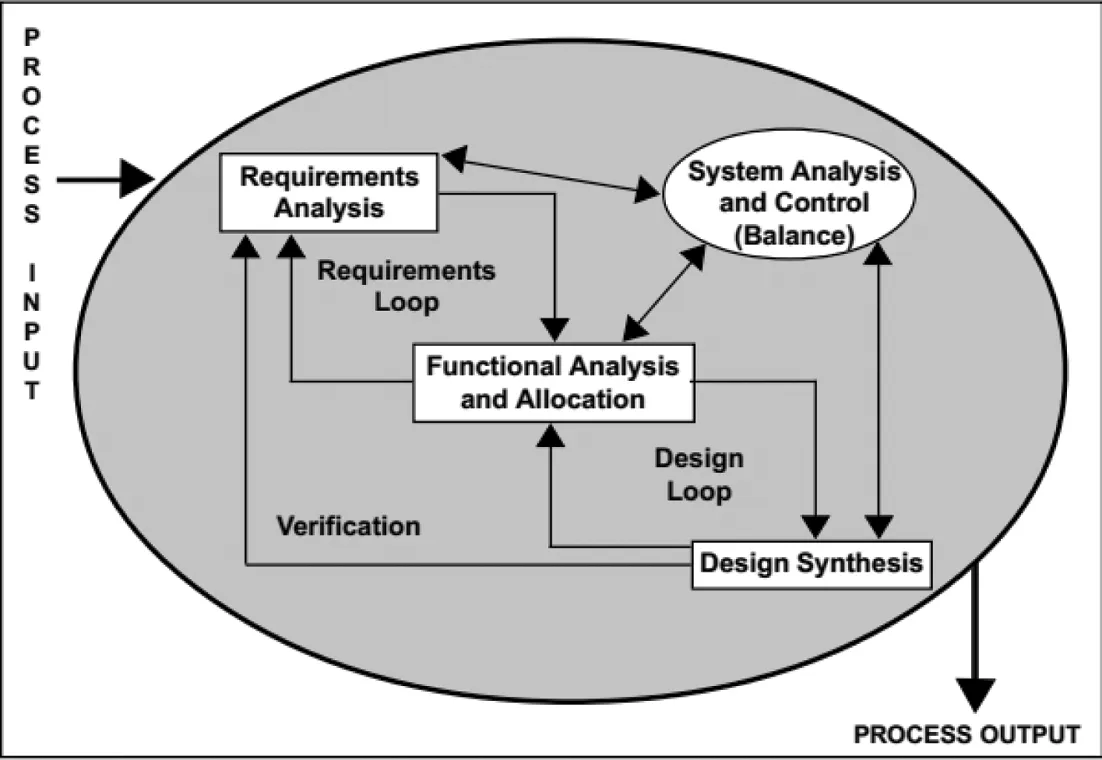
Figure 1 a typical system engineering process recommended by DoD[2]
1.1 Requirement Analysis.
Requirement analysis is the first analysis step in the Systems Engineering (SE) process. It takes in the external input, in the form of Stakeholder Requirements, and develops these Stakeholder requirements into functional and performance requirements, defining what the system must do, and how well it must perform.
The output of Requirements Analysis is a technical description of characteristics the future system must have in order to meet Stakeholder Requirements-not a specific solution-which will be evolved in subsequent development processes. The project team derives additional requirements resulting from analysis of the input Stakeholder Requirements as required to meet project and design constraints; defines the functional boundaries for the system to be developed; and identifies and documents any interfaces and information exchange requirements with systems external to the functional boundaries.
1.2 Functional Analysis.
This paper mainly focuses on functional analysis. The purpose of the functional analysis is to define the functionality that the system must have in order to meet the Stakeholder Requirements and to analyze the needs of the high-level functions, breaking them down into lower-level functions in the process, while decomposing the relevant performance requirements to the lower-levels. The result is a description of a product or project. This description (function profile) is commonly referred to as the System Functional Architecture.
High Level Functional analysis modeling (commonly known as the “black box” stage) is performed using use case diagrams (interactive objects to define the scope and external), activity diagrams (function flow), sequence diagrams (operation of internal and external processes or objects and the order in which exchanges between these objects occur) and state machines (executable model for verification of operation), as shown in Figure 2. Rhapsody is one proven software tool that can establish functional models using the above process.
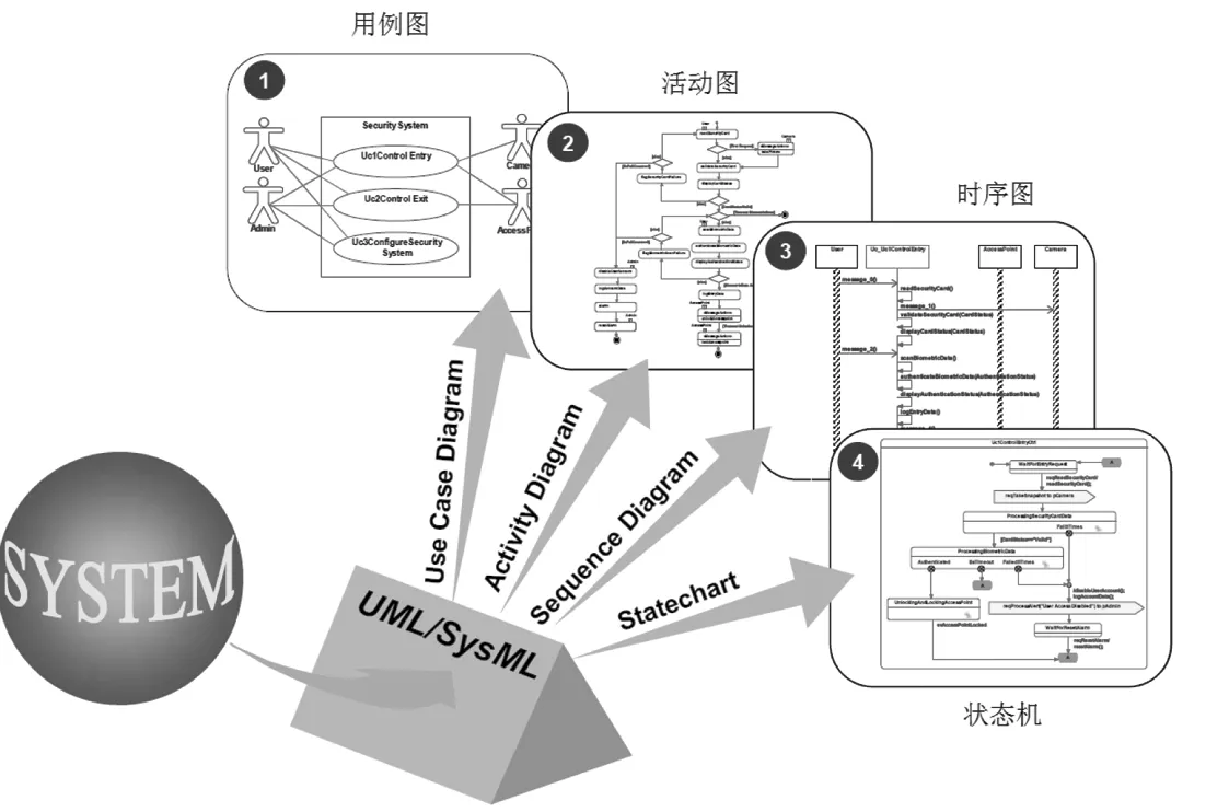
Figure 2 Systems development process using IBM Rhapsody software package
Detailed, lower level, functional analysis is the “white box” stage. During this stage the functional activity of the high level system is assigned directly to the functional activity of a range of lower level systems which results in the building of the systems integration architecture diagram.
The Design and synthesis process is to define the composition of products or physical objects, its output is usually referred to as a physical structure. Each physical object must meet at least one functional requirement and each physical object may also meet more than one function.
1.3 Design Synthesis
Design Synthesis is the process of defining the product and its composing parts, which outputs a physical architecture. Each part must trace to at least one requirement.
2 Civil aircraft ground deceleration Scenario Analysis
Civil aircraft is known as a high speed means of transporting passengers to and from different regions around the world. After the aircraft lands it decelerates with the contribution of three key factors:the wheel brakes, thrust reversers and aerodynamic braking (achieved by deploying the spoilers)[3].
In a typical commercial operationing scenario, a pilot often uses wheel braking, with the assistance of spoilers and thrust reversers, to reduce the ground speed to below 30 knots before exiting the active runway.
Wheel braking is the main means of deceleration. When the pilot operates the brake, it can effectively reduce aircraft taxi distance due to the friction between wheel and runway.
Thrust reversers also contribute to ground deceleration. During take off the aircraft engines eject high speed, high pressure air backwards, providing sufficient thrust to accelerate the aircraft to take off speed. During the ground deceleration scenario, the thrust created is diverted forwards causing the aircraft to decelerate. When the aircraft lands, the ground spoilers are fully deployed, reducing wing lift and increasing braking energy. Aircraft deceleration distance will be reduced.
Below is the system development process based on Rhapsody, through the establishment of use cases, functional flow and sequence diagrams with system requirements analysis, functional analysis and design synthesis, the model developed to guide system design.
2.1 Requirements Analysis
The purpose of requirement analysis is to identify use cases and to allocate requirements to the use cases. In order to analyze the needs of customers, (and to group the large amount of functional requirements into an organized order) the appropriate application scenarios, namely the modeling use cases, need to be determined. In the model the functional requirements are associated to use cases for functional analysis. When the use cases are set up, the relevant external actors are also identified relative to the system under development. This establishes the scope of the modeling.
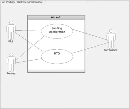
Figure 3 Deceleration ground use case diagram in Rhapsody Software
The Civil aircraft ground deceleration scenario has two use cases: normal landing deceleration and rejected takeoff (RTO) deceleration. Figure 3 is the model diagram showing the use cases, actors and their association relationship. It defines the boundaries of the system and interacts with external actors or stakeholders. The key actors in this analysis are the pilot, the runway and the surrounding environment (such as air temperature, rain, etc.).
2.2 Functional Analysis-Blackbox
In the functional analysis phase for each system use cases, the activity diagrams are modeled to reflect the operation of the system. The sequence diagrams are modeled to outline the actions and operations of the system under development and external actors as well as the interactions between them during ground deceleration.
Figure 4 is a ground deceleration activity diagram. The schematic shows firstly the pilot setting up the air spoilers to pre-position, arming auto brake and pulling the TCQ lever. Once the aircraft touches the ground at landing, the pilot can select automatic or manual brake. After touchdown, if certain logical criteria (as showed in the diagram) are met, the aircraft deploys its spoilers and thrust reversers for efficient deceleration process.
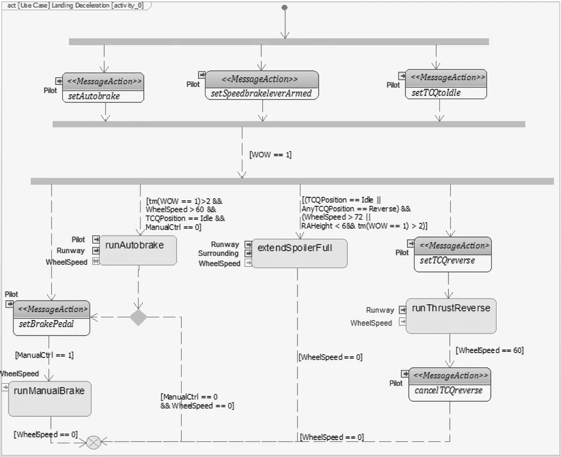
Figure 4 normal landing scenario ground deceleration activity diagram
Figure 5 is a ground deceleration sequence diagram. The diagram shows the implementation of three parallel deceleration modes.

Figure 5 normal landing ground deceleration sequence diagram
Moreover, we can use the function model for the validation of requirements. Validating requirements includes tracing requirements and showing that relationships are satisfied .
Tracing requirements collates all the functional requirements related to the corresponding use cases. Ensuring requirements are satisfied involves demonstrating that the relationship between each functional requirement is linked to an appropriate action, event and attribute. The requirements matrix and requirements coverage analysis are both used to provide requirements management data and can provide graphical output to visually demonstrate requirements coverage, as shown in Fig 6.

Figure 6 Schematic diagram of requirements coverage analysis
2.3 Functional Analysis-Whitebox
Comprehensive design of functional analysis, based on black-box model functional analysis phase, establishes sub-functions or subsystems and creates interfaces between sub-functions or subsystems.
At this stage, the first step to establish the ground deceleration scenario involving three systems/sub-functions, is shown in figure 7. The second step is to allocate black box stage activity diagram elements to the three systems using a swim lane diagram. This format provides a graphical language to describe and validate relationship information between the three subsystems, namely the relationship between the various sub-function interfaces between the layers of activity.
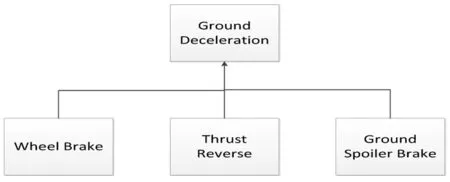
Figure 7 Functional Architecture of Ground Deceleration
3 Conclusions
It has been recognized that using MBSE provides significant benefits in the development of complex systems. Applying this method in design practice more effectively has been of the great interest in the Aerospace industry. This paper outlines the approaches of using MBSE for the functional analysis of civil aircraft and describes the details of a Rhapsody model for ground deceleration scenario.
The graphical diagrams include usecase diagrams, activity diagrams, sequence diagrams , and have been carefully set up to guide the complex system requirement definition. The model described in this paper can effectively relate to the operational behaviors of the aircraft and can be used to validate against the functional flow design, logic architecture design, and other related further analysis of the system.
Reference
[1] TangChao, FangJunwei, XieLin, ZhangLei, XiaYubing. Application of MBSE Method During Landing Gear System Design for Civil Aircraft. Civil Aircraft Design and Research, 2015,3:56-60.
[2] Systems Engineering Fundamentals (DoD), January 2001.
[3] Chen Yinchun, Song Wenbin, Liu Hong. Civil Aircraft Design. 2012.
TANG Chao FANG Junwei CHEN Nan
(Shanghai Aircraft Design and Research Institution, Shanghai 201210, China)
10.19416/j.cnki.1674-9804.2016.04.011

