Optimization of Forming Process of a U-rib by Gas Heating Based on Theoretical Prediction
Optimization of Forming Process of a U-rib by Gas Heating Based on Theoretical Prediction
Juan Blandon1,Shinji Takaba2,Toru Omae2,Naoki Osawa1and Hidekazu Murakawa3
Bending deformation of U-rib by gas heating is investigated using Thermal Elastic Plastic FEA employing an accurate heat source model.To validate our computational model,comparison between numerical analysis and experimental measurements are carried out.Good agreement is obtained for both temperature and deformation measurements.Inherent deformation method is employed to evaluate the overall behavior of U-rib under the influence of heating location and heating speed.Based on the prediction by FEA and using the inherent deformation method a new mathematical model describing the deformation of the U-rib is developed and evaluated for different combinations of heating conditions which can optimize the process of U-rib bending.
Forming,Line Heating,U-rib,Thermal Elastic-plastic,Inherent Deformation.
1 Introduction
Most of the large structures that we use in our daily lives such as ships,airplanes,cars,and others,are assembled using curved plates.In order to form flat plates into curved surfaces,external loads sufficiently strong to produce internal stresses capable of generating displacements,which result into permanent deformation of the flat plate are required.
These external loads can be produced through various methods,however,mechanical and thermo-mechanical forming are the most commonly employed.Mechanical plate forming consists on pressing the plate against a die of appropriate shape,or by feeding the plate through a set of rollers to achieve the desired curvature.In case of thermo-mechanical forming,permanent deformation is produced through thermalstresses generated by line heating and subsequent cooling.These heating lines can be applied using three different types of heat sources,gas heating,induction heating and most recently laser heating.The advantage of line heating over mechanical forming is that it provides more freedom to achieve complex geometrical shapes such as those found in ship hulls.However,it still relies in most of the cases on empirical knowledge of workers with years of experience.As a consequence,factors such as production costs and delivery time are difficult to control.This is the main reason why plate forming by means of line heating has been an active topic of research during the last 60 years.
To understand the mechanism of plate forming by line heating,there are two main points that need to be covered.The first point,is the heat conduction problem.Rosenthal(1946), first derived an analytical solution of the temperature field under point and line heating sources using the heat conduction equation for the quasistationary state.Moshaiov and Latorre(1985)investigated the time varying temperature field in the plate during flame bending process.Osawa(2007)proposed a new hypothesis of heat transmission during line heating.They developed a technique to identify the distribution of the temperature of the gas adjacent to the plate surface and local overall heat transfer coefficient(convection and radiation).
The next point is dealing with the elasto-plastic deformation problem.The inherent strain method Murakawa(2010)has been proven to be a powerful tool to predict plate deformation by line heating.Through a series of studies Ueda(1993,1994)developed a computer aided process planning system for plate bending using line heating.They investigated the relationship between the final form of the plate and the inherent strain formed in the plate.A method to decide the heating line locations as well as the required inherent strain was proposed.They developed new three dimensional finite element method codes to predict plate deformation due to line heating,avoiding costly experiments.They also investigated the influence of secondary factors affecting the plate deformation via computational methods,such as the influence of the initial curvature and in plane residual stress on the inherent deformation produced by a single line heating.Vega(2008)studied the influence of multi-heating lines on plate forming by line heating.Vega(2010)also evaluated the influence of edge effect on inherent deformation for a wide range of plate thickness and heating conditions.Recent efforts in line heating research deal with automation of the process itself.The most impressive advance in recent years is IHIMU-α,Tango(2011),an advanced line heating machine for hull steel forming capable of automatically handling the whole process.
In general,most of the line heating research done up until now is focused on its application in the shipbuilding industry.This study deals with bending of U-ribs used to stiffen curved shape structures such as curved bridges and highways.The main goal of this research is to optimize the U-rib bending process using line heating,from the point of view of quality as well as energy consumption.To avoid costly and time consuming experiments,thermal elastic plastic FE analysis was used in this study.
2 Methods of Analysis
2.1 Thermal elastic plastic FE analysis
The thermal-mechanical behavior during the process of bending by line heating is analyzed using uncoupled thermal/mechanical formulation.However,the uncoupled formulation considers the contribution of the transient temperature field to strains and stresses through thermal expansion,and temperature-dependent physical and mechanical properties.
The solution procedure consists of two steps.First,transient temperature distribution history is computed using FE heat transfer analysis.Then,the transient temperature distribution obtained from the heat transfer analysis is employed as a thermal load in the subsequent Thermal-Elastic-Plastic mechanical analysis.Stresses,strains and displacements are then computed.These algorithms are all incorporated in the in-house code JWRIAN(Joining and Welding Research Institute Analysis program).In inherent strain method or inherent deformation method,local shrinkages produced by welding or line heating are introduced in FE model as initial strain or initial deformation.Then,the distortion and the residual stresses are computed as an elastic problem.The computational time is greatly reduced compared to the thermal elastic plastic analysis.Ueda(1977),Murakawa(2010).
2.2 Heat source model
In this study,heat is applied by a gas heating torch.In order to get accurate deformation in thermal elastic plastic analysis of the gas heating process,we need an accurate heat source model.In this study,gas heating torch is modeled using a heat source model proposed by Osawa(2007).
This hypothesis can be represented in terms of a linear relationship between the heat flux q and heated surface temperature as shown in equation(1),Osawa(2007).

Where,t is time and r is the distance from the projection of the center of the heating nozzle on the plate.Time histories of heat flux q(t,r)and temperature Ts(t,r)on the heated surface are predicted using inverse heat transfer analysis from measured temperatures TBon the back surface of the plate during spot heating test using the experimental setup shown in Fig.2.Then,the two heat input parameters α(r)and TG(r)can be evaluated by performing a linear regression analysis on the relation between q(t,r)and Ts(t,r).
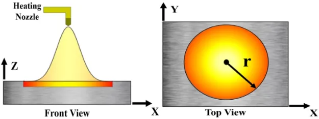
Figure 1:Schematic view of gas heating torch heat source model.
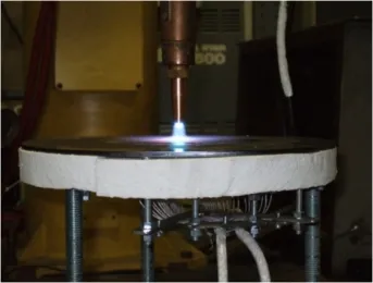
Figure 2:Experimental setup for evaluation of heat input parameters.
Common fuel gases used in forming by gas heating are acetylene and propane.In this study,the heat input parameters TG(r)and α(r)shown in Figures 3 and 4 were obtained from seven different spot heating tests using three different oxy-acetylene gas heating torches.Heat input parameters measurements using propane fueled gas heating torches are planned to be done in the future.
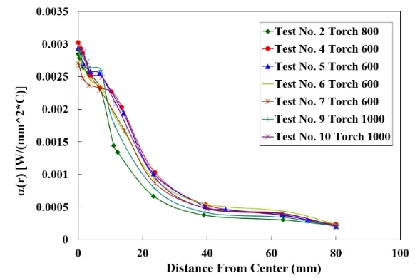
Figure 3:TG(r)temperature of the gas adjacent to the plate surface.

Figure 4:Local heat transfer coefficient α(r)adjacent to the plate surface.
3 U-rib Bending Description
Experiments have been performed for bending of a 7 m length U-rib.Bending was done by applying two heating lines starting at the same time and traveling with speeds of 8 and 16 mm/s.These two heating lines were applied on the top and on the bottom of one side of the U-rib outer surface as shown in Fig.5.Heat was applied using propane fueled gas heating torches.
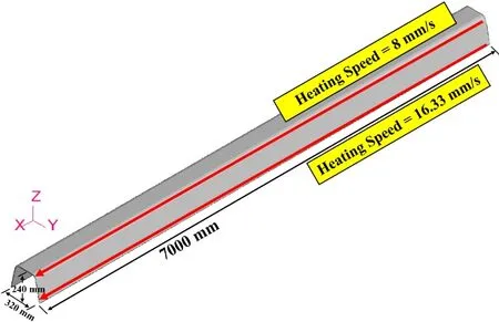
Figure 5:7m U-rib FE model.
4 U-rib analysis and results
As mentioned in 2 above gas heating process is studied using thermal elastic plastic FE analysis.First,thermal analyses to compute temperature distributions are carried out.Later mechanical analyses are done to evaluate the deformation of the U-rib due to the influence of thermal loads.
4.1 Selection of heat source parameters
In order to select proper heat input parameters,the heat source model proposed by Osawa(2007)was implemented into our in-house code.Since propane heating parameters are not available,the seven different sets of acetylene heat input parameters shown in Figs.3 and 4 were used to carry out thermal analyses.To save computational time,temperature distributions produced by two simultaneous heating lines moving with different speeds were computed using a 1 m U-rib FE model.
To emulate the way of measuring the temperature in experiments,the temperature was evaluated at the top and at the bottom of the inner surface of the U-rib model central cross section,as shown in Fig.6.Analysis was done for all the seven different thermal analyses results.The white markers plotted in Fig.6 correspond to the three sets of maximum attained temperatures measured in experiments.
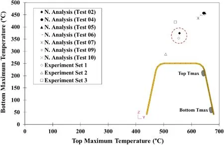
Figure 6:Comparison between the maximum achieved temperatures obtained from thermal analyses and U-rib experimental measurements.
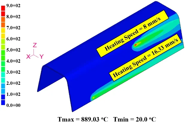
Figure 7:Transient temperature distribution of the one meter U-rib at 40 s from the start of heating as obtained by thermal analysis.
From these results it can be concluded that the set of heat input parameters corresponding to spot heating Test 02 are the ones with characteristics similar to those used in U-rib bending tests in actual practice.Therefore,we selected these heat input parameters as the heating conditions of our heat source model.
Figure 7 shows the transient temperature distribution at 40 s from the start of heating using the set of heating input parameters given by Test 02.It can be seen that although the model is short compared to the actual length of the U-rib used in real practice,the 1 m U-rib model length is long enough to give a good prediction of the maximum attained temperatures.
4.2 Thermal analysis and results
After selecting the heat input parameters,thermal analysis was carried out on a 7 m U-rib FE model.As shown in Fig.8 two simultaneous heating lines,one on the top with a speed of 8 mm/s and one on the bottom with a speed of 16 mm/s are adopted in the analysis.
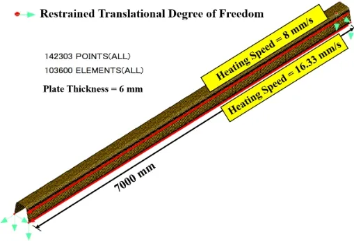
Figure 8:Seven meter U-rib FE model.
Figure 9 shows the transient temperature distribution for the 7 m U-rib model at 400 s from the start of heating,Maximum attained temperature was evaluated at eight different points on the inner surface of the U-rib FE model as shown in Fig.10.As it can be seen in Fig.11,good agreement was found with the experimentally measured maximum temperatures.
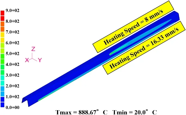
Figure 9:Transient temperature distribution of 7 m U-rib at 400 s from the start of heating.

Figure 10:Inner surface points where maximum achieved temperature was evaluated.

Figure 11:Comparison between measured and computed maximum achieved temperatures on the 7m U-rib.
4.3 Mechanical analysis
After selecting proper heat input parameters,deformation of the 7 m U-rib due to thermal load produced by the two heating lines is computed.Boundary conditions given to this model are such that the 4 corner points are fixed in the vertical direction,displacements in the other 2 directions are restrained to prevent in plane rigid body motion as shown in Fig.8
Figure 12 shows the deformation of the 7 m U-rib produced by the two simultaneous heating lines.In order to compare the results of numerical analysis with those measured in actual practice,displacement was evaluated on both the heated and non-heated surfaces on the same points where displacement was experimentally measured as shown in Fig.13.
In a previous study done by Murakawa(2012),the overall deformation of the U-rib due to gas heating was defined in terms of four components as shown in Fig.14.These four components of deformation can be expressed in terms of the y and z displacements of points A and B on the U-rib center cross section as:

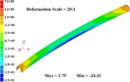
Figure 12:Y Displacement Contour of 7 m U-rib due to gas heating.
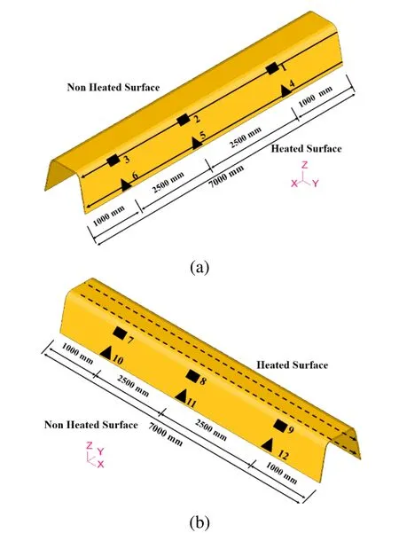
Figure 13:Positions where the displacement was evaluated for numerical and experimental results,(a)7 m U-rib heated surface,(b)7m U-rib non heated surface.
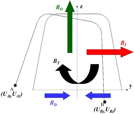
Figure 14:Deformation components of the U-rib due to gas heating.
Within these four components of deformation,in plane bending is the desired deformation,meanwhile the other three components,out of plane bending,twisting and distortion of the cross section are considered as undesired deformations.Figure 15 shows comparisons between thermal elastic plastic FE Analysis results and experimental measurements for both,heated and non-heated sides of the 7 m U-rib.From this two figures it can be seen,that the magnitude of in-plane bending,as defined by Eq.2,obtained for numerical analysis has good agreement with the values of in plane bending measured on the heated surface.On the non-heated side there is a difference of 6%between the in plane bending obtained from numerical analysis and the one measured in experiment.Besides the natural scatter of experimental results,the main reason to this difference may be attributed to the difference of the fuel gas used in experiments(propane),and the one used to evaluate heating parameters used in analysis(acetylene).
However from the fact that the deformation tendency of both numerical results and experimental measurements has good agreement,it can be concluded that the heat source model is accurate enough to proceed to the final stage of our study,which is the optimization of the U-rib bending by gas heating.

Figure 15:Comparison between the surface deformations obtained for numerical analysis and experimental measurements,(a)7 m U-rib heated surface,(b)7 m U-rib non-heated surface.
5 Optimization of the U-rib bending process by means of gas heating
The main objective of the optimization is to be able to predict the combination of heating locations and traveling speeds which produces the desired amount of in plane bending with less undesired deformation while consuming less time and fuel gas.This study has been divided into two stages,as shown on Fig.16.
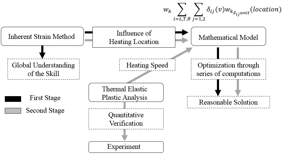
Figure 16:Optimization of the U-rib bending process- flow analysis.
Generally the deformation of the U rib w can be described by the following equation

Where δ is the inherent deformation produced by line heating applied at a specific location with a specific traveling speed and wδrepresents a response function which gives the deformation produced by unit inherent deformation.The equation in Fig.16 describes the full form of the equation used to optimize the bending of U-rib,i.e.

Where wkis the k-th component of deformation and k represents the four components of deformation of the U-rib:in-plane bending,out of plane bending,twisting,and distortion of cross section.δijis the i-th component of inherent deformation caused by heating line j.Where i=L(longitudinal),T(transverse)and θ transverse bending),and wkδijunitis the k-th component of deformation produced by the i-th component unit inherent deformation caused by two heating lines j.Due to the fact that the magnitude of distortion of cross section is considerably small it is neglected in this study.
First,inherent deformation δijwas evaluated.Thermal elastic plastic analysis of the line heating process on the 2 m U-rib FE model shown in Fig.17 was carried out for different heating locations between locations 1 and 16,with different traveling speeds between 8 and 32 mm/s.Figures 18,19,and 20 show the influence of the heating location and speed on inherent longitudinal shrinkage,inherent transverse shrinkage and the inherent transverse bending respectively.In case of inherent longitudinal and transverse shrinkage,inherent deformation becomes smaller when the heating line is close to the top and the bottom edges.As for transverse bending it changes linearly with respect to the heating location.

Figure 17:Flat plate model used to compute the inherent deformation for different traveling speeds.
In order to verify the accuracy of the inherent deformation δijcomputed through thermal elastic plastic analysis shell elastic analysis was carried out using a 7 m U-rib shell model and compared with experimental measurements.The comparison is shown in Fig.15.Good agreement was obtained between the three methods namely thermal elastic plastic analysis,shell elastic analysis and experiment.It proves that the inherent deformation δijevaluated by the thermal elastic plastic analysis is accurate enough to be employed in the optimization analysis.
The location where the heating line is applied has major influence on the deformation of the U-rib as shown by wkδijunitin equation 7.This influence was investigated using shell elastic analysis applying unit inherent deformation namely longitudinal shrinkage,transverse shrinkage and transverse bending on different heating locations varying from 1 to 16 as shown in Fig.21.
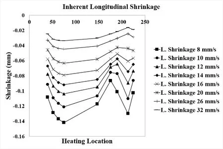
Figure 18:Distribution of inherent longitudinal shrinkage obtained for different heating locations and traveling speeds on a 2 m U-rib.

Figure 19:Distribution of inherent transverse shrinkage obtained for different heating locations and traveling speeds on a 2 m U-rib.
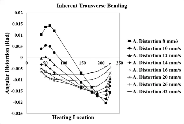
Figure 20:Distribution of inherent transverse bending obtained for different heating locations and traveling speeds on a 2 m U-rib.
Figure 22 shows the deformation of the U-rib when applying only unit longitudinal inherent deformation on different heating locations.The same was carried out for other two components of unit inherent deformation,namely,unit inherent transverse shrinkage and unit inherent transverse bending.
In order to make a visual selection of the optimum heating conditions,Eq.7 was evaluated for all possible combinations within the practical range,that is traveling speeds between 8 mm/s and 32 mm/s and heating locations from 1 to 16.Figure 23 shows the result of this computations for the 7 m U-rib FE model.In this figure the x axis represents the desired deformation(in-plane bending)and the y axis represents the undesired deformation(twisting and out of plane bending).
This graph can be divided into three regions as seen in Fig.23.Out of these three regions,the best one is region B.In case of region A,the ratio between desired deformation and undesired deformation is not favorable,thus,the heating conditions in this region are not considered.Heating conditions in region C are also discarded because they produce in-plane bending in the opposite direction.
The range of in-plane bending that can be produced by heating conditions in region B,ranges from 1 up to 50 mm.The white markers in Fig.23 represent some of the heating conditions used in actual practice for bending of 7m U-rib.It can be seen that all of these actual heating conditions are within region B,moreover,producing low amounts of undesired deformation.
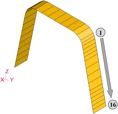
Figure 21:Heating locations on the heated surface of the U-rib.

Figure 22:Deformation components of the 7m U-rib caused by unit longitudinal inherent strain at different heating locations.
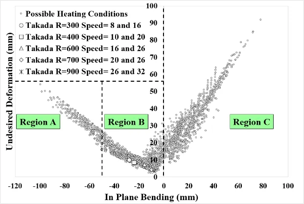
Figure 23:Different sets of heating conditions for bending of 7 m U-rib.
Figure 23 turns out to be a very interesting graph due to various reasons.First,as concluded in the first stage of this study by Murakawa et al.(2012),there is more than one set of heating conditions which can produce same amount of desired inplane bending.Second,heating conditions within region B,are in good agreement with the range of in-plane bending produced in actual practice.Finally,it is well proven that the experience of skilled workers is never something to be underestimated,from the fact that heating conditions being used in actual practice manage to produce the desired amount of in-plane bending while producing a minimum amount of undesired deformation,thus,not compromising the quality of the final product.
However there are other alternatives to obtain the same amount of in-plane bending,consuming less time and fuel gas.After carefully inspecting the heating conditions within region B,optimum heating conditions were concluded to be the ones presented in Fig.24.This heating conditions consist of applying two heating lines at locations 2 and 10.Travelling speed is fixed at 32 mm/s in the bottom,while travelling speed in the top is a function of in-plane bending,this speed can be evaluated with the function presented in Fig.25.As presented in Fig.26,using this new set of heating conditions,the same amount of in-plane bending can be obtained while consuming less heating time,as well as fuel gas.
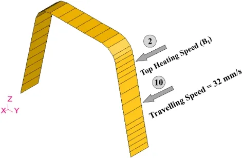
Figure 24:Schematic view of optimum heating conditions for bending of 7 m U-rib.
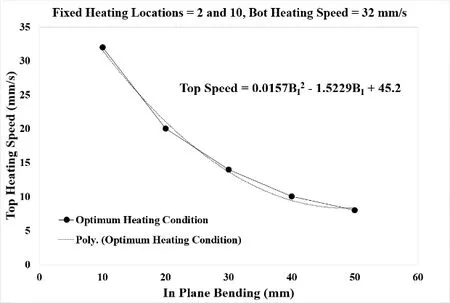
Figure 25:Optimum heating conditions for bending of 7 m U-rib.
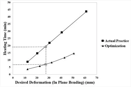
Figure 26:Heating time consumption comparison between actual 7 m U-rib bending practice and new proposed optimum heating conditions.
6 Conclusion
A preliminary study to optimize the U-rib bending process using an idealized heat source model was carried out.On this study,unlike the previous one,an accurate heat source model was employed to represent the temperature field produced by gas heating torch.Temperature and deformation evaluated in numerical analysis had good agreement with those measured in experiments.A mathematical model to represent the deformation of the U-rib as a function of heating location,and heating speed was developed.Optimum heating conditions for bending of U-rib were proposed.This optimum heating conditions manage to produce the same amount of desired deformation,saving time and fuel gas consumption,compared to the heating conditions used in actual practice.
Moshaiov,A.;Latorre,R.(1985):Temperature distribution during plate bending by torch flame heating.Journal of Ship Research,vol.29,no.1,pp.1-11.
Murakawa,H.;Deng,D.;Ma,N.(2010):Concept of inherent strain,inherent stress,inherent deformation,and inherent force for prediction of welding distortion and residual stress.Transactions of JWRI,vol.39,no.2,pp.103-105.
Murakawa H.;Matsuo Y.;Takaba S.;Omae T.(2012):Process optimization for bending U-rib by Line heating based on theoretical prediction,Proceedings of the Visual-JW2012,pp.110-111.
Osawa,N.;Hashimoto,K.;Sawamura,J.;Kikuchi,J.;Deguchi,Y.;Yamaura,T.(2007):Development of heat input estimation technique for simulation of shell forming by line-heating.CMES:Computer Modeling in Engineering&Sciences,vol.20,no.1,pp.45-53.
Rosenthal,D.(1946):Theory of moving source of heat and its application to metal treatments.Transactions of American Society of Mechanical Engineers,vol.68,pp.849-866.
Tango,Y.;Ishiyama,M.;Suzuki,H.(2011): “IHIMU-α"g A fully automated steel plate bending system for shipbuilding.IHI Engineering Review,vol.44,no.1,pp.6-11.
Tomita,Y.;Osawa,N.;Hashimoto,K.;Shinkai,N.;Sawamura,J.;Matsuoka,K.(2001):Study on heat transfer between gas flame and plate during line-heating process.Practical Design of Ships and Other Floating Structures,,pp.389-396.Ueda,Y.;Fukuda,K.;Nakacho,K.;Endo,S.(1977):Fundamental Concept in Measurement of Residual Stresses Based on Finite Element Method and Reliability of Estimated Values.Theoretical and Applied Mechanics,vol.25,pp.539-554.
Ueda,Y.;Murakawa,H.;Rashwan,A.M.;Okumoto,Y.;Kamichika,R.(1994):Development of computer-aided process planning system for plate bending by line heating(Report 1)-Relation between final form of plate and inherent strain.Trans.SNAME,Journal of Ship Production,vol.10,no.1,pp.59-67.
Ueda,Y.;Murakawa,H.;Rashwan,A.M.;Okumoto,Y.;Kamichika,R.(1994):Development of computer-aided process planning system for plate bending by line heating(Report 2)-Practice for plate bending in shipyard viewed from aspect of inherent strain.Trans.SNAME,Journal of Ship Production,vol.10,no.4,pp.239-247.
Ueda,Y.;Murakawa,H.;Rashwan,A.M.;Okumoto,Y.;Kamichika,R.(1994):Development of computer-aided process planning system for plate bending by line heating(Report 3)-Relation between heating condition and deformation.Journal of Ship Production,vol.10,no.4,pp.248-257.
Ueda,Y.;Murakawa,H.;Rashwan,A.M.;Okumoto,Y.;Kamichika,R.(1993):Development of computer-aided process planning system for plate bending by line heating(Report 4)-Decision making on heating conditions,location and direction(mechanics,strength&structural design).Transactions of JWRI,vol.22,no.2,pp.305-313.
Vega,A.;Rashed,S.;Tango,Y.;Ishiyama,M;Murakawa,H.(2008):Anal-ysis and prediction of multi-heating lines effect on plate forming by line heating.CMES:Computer Modeling in Engineering&Sciences,vol.28,no.1,pp.1-14.
Vega,A.;Osawa,N.;Rashed,S.;Murakawa,H.(2010):Analysis and prediction of edge effect on inherent deformation of thick plates formed by line heating.CMES:Computer Modeling in Engineering&Sciences,vol.69,no.3,pp.261-279.
1Graduate School of Engineering,Osaka University,Japan.
2Takadakiko Co.LTD,Japan.
3Joining and Welding Research Institute,Osaka University,Japan.
 Computer Modeling In Engineering&Sciences2015年13期
- Computer Modeling In Engineering&Sciences的其它文章
- Modified SFDI for Fully Nonlinear Wave Simulation
- Analysis of Symmetry Breaking Bifurcation in Duffing System with Random Parameter
