Modeling the Axial Splitting and Curling of Metal Tubes under Crush Loads
2015-12-13 03:32:50XuandWaas
Computers Materials&Continua 2015年6期
W.Xuand A.M.Waas
Modeling the Axial Splitting and Curling of Metal Tubes under Crush Loads
W.Xu1and A.M.Waas2
Plastic deformation and splitting are two important mechanisms of energy dissipation when metal tubes undergo axial crushing.Isotropic J2plasticity theory combined with a failure criterion is used to model axial splitting and curling of metal tubes undergoing axial crush.The proposed material model is implemented within a finite element(FE)framework using the user material subroutine VUMAT option available in the commercial code ABAQUS.Experimental results from literature are used to validate the model.The predicted splitting and curling patterns as well as the load-displacement response agree well with the experimental observations.The present material model is also used to predict the number of axial cracks in splitting the tube.
Splitting,Curling,Energy absorption,Plasticity and fracture,Crack number prediction.
1 Introduction
Energy absorbing devices are designed to protect human life in a variety of practical applications.In automobiles,thin walled tubes are used as crush cans to absorb and dissipate energy transmitted to a vehicle undergoing a front end collision.Various shapes of thin-walled metal structures have been proposed to achieve high energy absorption capability[Huang,Lu,and Yu(2002);Lu and Yu(2003)].The main energy-dissipating mechanisms for thin-walled metal structures are plastic deformation,tearing and friction[Reid(1993)].Many studies have been carried out on a metal tube subjected to compression between two flat platens,[Lu and Yu(2003);Reid(1993);Guillow,Lu,and Grzebieta(2001);Hanssen,Langseth,and Hopperstad(2000)].Axial buckling and material folding were observed as the most significant deformation mechanisms in these experiments.The main energy absorbing mechanism of this type of metal tube is plastic deformation.The rigid-plasticanalytical model proposed by Alexander[Alexander(1960)]was used and modified[Abramowicz and Jones(1984)]to predict the crushing load-displacement response.Meanwhile,great effort has been expended to study dynamic crushing behavior of tubes by using computer simulations aided by the finite element method.A historical review of the development of the finite element method for solving dynamic crushing problems was given in[Belytschko,Liu,and Moran(2000)].In general,the use of finite element simulations has been shown to be versatile in capturing the salient features of tube crush,either as single or multiple collections of tubes,see for example,[Bathe,Walczak,Guillermin,Bouzinov,and Chen(1999);Galib and Limam(2004);Tarigopula,Langseth,Hopperstad,and Clausen(2006);D’Mello,Guntupalli,Hansen,and Waas(2012)].
Another crushing experiment is that of a tube subjected to compression between a flat plate and a shaped die.A typical experimental set-up is shown in Fig.2a.The energy-dissipating mechanisms of this type of crushing are plastic deformation,tearing and friction.The observed collapse mode of this test is splitting and curling,which is schematically shown in Fig.2b.This collapse mode has long stroke of over 90%of the initial tube length[Reid(1993);Reddy and Reid(1986)].The steady load of this kind of tube is always much lower than the same tube subjected to compression between two flat plates.However,from the viewpoint of energy absorption,it is an efficient energy absorption device.Besides the experimental work and findings,approximate analytical methods were proposed to predict the number of cracks,the curling radius and the steady load.These analytical methods[Huang,Lu,and Yu(2002);Reid(1993);Reddy and Reid(1986)]are useful to understand the behavior of the splitting and curling of the tubes.They have some limitations as well.For example,prior analytical work cannot predict the splitting and curling process and the load-displacement response.The splitting and curling process are very complex,which involves contact,material nonlinearity,crack initiation and propagation.Therefore,an approach that uses a FE based framework,suitably tailored to study axial splitting and curling is presented in this paper.There are many methods developed to model crack initiation and propagation[Belytschko and Black(1999);Silling(2000);Dong and Atluri(2013);Han and Atluri(2014a,b)].However,to the author’s knowledge,there are no prior numerical studies reported in the open literature that simultaneously considers the interaction of the splitting and curling deformation mechanisms.
In this paper,we propose a method to predict the splitting and curling process by using the FE method.Isotropic,elastic-plastic J2flow theory with an associated yield criterion,combined with a fracture criterion is used to model the material nonlinear and cracking behavior of the metal tubes.The proposed material model is implemented through ABAQUS/EXPLICIT user material subroutine VUMAT.The experimental study reported in[Huang,Lu,and Yu(2002)]is used to validate the present approach.Our results show that the present numerical approach is able to predict the splitting and curling process quite well.Furthermore,the predicted curling radius and load-displacement response are found to compare well with the corresponding experimental results.Having obtained confidence in the material model,the number of cracks in the axial splitting of the tube is predicted and reasonable results are obtained.

Figure 1:Experiment setup and fracture pattern of metal tubes,Ref.(Huang et al.,2002)
2 Overview of the explicit finite element method
The well-known equation of equilibrium governing the dynamic response of a system of finite elements is

where M,C,and K are the mass,damping and stiffness matrices;R(t)is the vector of externally applied loads,which is a function of time t.Here,u,˙u and¨u are the displacement,velocity and acceleration vectors of the finite element nodes.To solve the above equations,the explicit dynamics analysis procedure in ABAQUS/Explicit is used[ABAQUS(2011);Bathe(1996)].This procedure is based on the implementation of an explicit integration rule together with the use of diagonal or0lumped0element mass matrix.The central difference integration rule is used to approximate the acceleration and velocity.

Substituting Eq.(2a)and Eq.(2b)into Eq.(1),the displacement at time(t+∆t)is obtained by the following equation.

For simplicity,let the damping matrix equal the null matrix.We have,

where,B is the strain-displacement matrix,which is the derivation of the shape function.In Abaqus/Explicit,lumped mass technique is used to obtain diagonal mass matrix M.As a result,the displacement components are easy to obtain by using the following equation,once the effective load vector is determined.

3 A plasticity and cracking material model
There are many elastic-plastic constitutive models[Souza Neto,Peric,and Owen(2008);Gurson(1977);Tvergaard and Needleman(1984)]and failure criteria[Wierzbicki,Bao,Lee,and Bai(2005);Xue(2007);Bai and Wierzbicki(2010)]developed to study the deformation and fracture of ductile materials.Recent examples of using some of these models to predict the crack path,load displacement response of the Sandia fracture challenge can be found in Ref.[Boyce,Kramer,Fang,and et al(2014)].In general,the contemporary plasticity models perform very well,due to their capability of considering the effect of stress triaxiality or(and)the Lode angle[Pack,Luo,and Wierzbicki(2014);Gross and Ravi-Chandar(2014);Nahshon, Miraglia,Cruce, Defrese,and Moyer(2014)].These modern material models are important to enhance ductile fracture predictability.
In practice,the selection of a certain material model is not only dependent on its accuracy,but also dependent on its availability and affordability.Besides the constitutive model and failure criterion,the associated material properties are required as well to predict the response of a structure.Except the simple dog bone tensile test to obtain the engineering stress-strain relation,more tests are required to determine the material constants appearing in contemporary constitutive models and failure criteria,[Pack,Luo,and Wierzbicki(2014);Gross and Ravi-Chandar(2014); Nahshon,Miraglia,Cruce,Defrese,and Moyer(2014)].Even when the required material constants are available,it is still not easy to predict the deformation and cracking behavior of ductile materials in a structure,because of the computational complexity.To successfully adopt advanced material models,very fine three dimensional elements are required to obtain accurate stress and strain fields at the crack tip[Gross and Ravi-Chandar(2014);Nahshon,Miraglia, Cruce,Defrese,and Moyer(2014)].For example,the smallest element size and total element number used in Ref.[Gross and Ravi-Chandar(2014)]for the Sandia fracture challenge were 31.75µm and 2.25 million,respectively.The corresponding computational demand was 2000h cpu time[Gross and Ravi-Chandar(2014)].As a result,it is still a challenge for engineers and researchers to use limited material properties and computation resources to simulate and predict ductile fracture of a structure.
Based on these considerations,in this paper,the isotropic J2plasticity model combined with a failure criterion is used to model the splitting and curling of a metal tube.The splitting behavior is captured by using a failure criterion.The tube is assumed to be split when the strain and stress in the hoop direction exceed critical values.That is

where,εcrand σcrare the critical strain and stress,respectively,which are material dependent.It is noteworthy that the strain in Eq.(7)is not the equivalent plastic strain,which is widely used as a failure parameter.The critical equivalent plastic strain is not a constant,but a function of the stress triaxiality and Lode angle[Bai and Wierzbicki(2010)].Due to the limited material properties presented in[Huang,Lu,and Yu(2002)],this function is not available.However,if constant critical hoop strain is used,the actual equivalent plastic strain at failure is dependent on the stress state.The determination of the critical parameters are given in section 4.3.The stress criterion is used to eliminate unrealistic results,if only the present strain criterion is used.This aspect will be discussed in section 5.
Once the strain and stress at a material point(integration point)meet this requirement,Eq.(7),element deletion is used[ABAQUS(2011)].One of the advantages of using explicit finite element method is that the material properties can be degraded without introducing numerical divergence problems which usually occurs in implicit finite element schemes when material softening or cracking is involved.The disadvantage of explicit finite element method for solving quasi-static problem is computational time.However,the explicit method does not require storing the global stiffness matrix and performing large matrix algorithm calculations,as shown in Eq.(6).Furthermore,the computer clock speeds continue to become faster,and efficient.It is practical to run quasi-static simulations by using an explicit finite element method.Another advantage of using explicit finite element method is that once the present method is validated,it can be extended to analyze the impact crushing,where rate effects may be required to be considered.For the dynamic impact,the total time is always very short(10−3s),the computation demand is far less than that needed in the quasi-static simulations.
The practical implementation of the present model into ABAQUS/EXPLICIT user material subroutine VUMAT is given in the appendix.
4 Crushing experiment and finite element model
The aluminum and mild steel tubes tested in[Huang,Lu,and Yu(2002)]are used to validate the capability of the proposed material model.A short overview of the experiment is given below.
4.1 Overview of the crushing experiment
The axial splitting and curling behavior of metal tubes were experimentally studied by Huang et al.[Huang,Lu,and Yu(2002)],who tested various circular tubes.Figure 2a shows the experimental setup.The variables in the tests were:the angle of the die,the thickness,the diameter and material of the tube.Three different angles,α =45◦,60◦and 75◦,were designed for the conical die.The dies were made of mild steel and heat-treated to harden the surface.The tested tubes were 200mm long with the ratio of the diameter d to the thickness t ranging from 15 to 50.Eight uniformly spaced saw-cuts were made for all the specimens to obtain splitting and curling modes while preventing other collapse modes.The initial length of the sawcuts was 5mm,while the width was not reported.A short cylindrical mandrel inside the tube shown in Fig.1a was used to prevent the tube from tilting.The cross-head of the test machine compressed the tube at a constant speed of 0.0333mm/s.
At the beginning,the strips between the initial saw-cuts buckled and flared as guided by the die,which resulted in the circumferential stretch of the tube.When the stretch reached a certain level,cracks initiated from some initial saw-cuts and propagated along the axial direction due to the continuous ductile tearing.The formed strip rolled up into curls.The curls were observed to be almost constant radius,which was dependent on the tie angle,tube dimension and material.A typical splitting and curling pattern is shown in Fig.2b[Huang,Lu,and Yu(2002)].The experimental radius of the curls,splitting and curling patterns and load-displacement curve will be used to validate the findings of the present model.
4.2 Finite element model


Figure 2:A typical three dimensional finite element model
4.3 Determination of plastic strain-stress relationship
The experimental stress-strain curves for the aluminum and mild steel used for the tubes were obtained from standard coupon test for each tube thickness.For the same material,the experimental curves were close[Huang,Lu,and Yu(2002)].The average value given in Ref.[Huang,Lu,and Yu(2002)]is plotted in Fig.3.Both hardening and softening are observed from these curves.The softening is due to the local necking.Once necking has occurred,stress and strain are no longer uniformly distributed within the gauge section.Therefore,the engineering stressstrain curve after necking cannot be used to describe the material behavior.Inverse finite element method is widely[Kamaya and Kawakubo(2011);Joun,Choi,Eom,and Lee(2007)]used to obtain the equivalent plastic strain-stress response for ductile material.The procedure is given as follows.
•1.Tensile test to determine the engineering stress strain curve The engineering stress-strain curve is obtained by conducting tension test following the ASTM standard.The geometrical dimensions of tensile specimen is shown in Fig.4.The engineering strain is calculated from the displacement measured between the gauge length.
•2.Finite element simulation In the finite element simulation,only one quarter of the longitudinal crosssection in the gauge length(shown in Fig.4b)is modeled.The specimen is modeled to be slightly thinner in the middle than the ends(as shown in Fig.4)to trigger local necking.Symmetrical boundary conditions are appropriately prescribed.On the right end,uniform displacement is applied on its surface.The model is meshed by using three dimensional element C3D8R in ABAQUS.The element size is 1mm×1mm×1mm,which will be used for modeling the tube.The elastic modulus measured from the tension test are used.The Possion’s ratio 0.3 is used for both aluminum and mild steel.An assumed equivalent plastic strain-stress relation is used for the elastic-plastic simulation.Geometric nonlinearity is used in the finite element analysis.The resulted engineering strain stress curve,which is calculated from the load-displacement response,is used to compare with the experimental results.The assumed equivalent plastic strain-stress relation is iteratively changed until the resulting engineering strain stress response can match the experimental result well.
After many iterations,the equivalent plastic strain stress relations for aluminum and mild steel are determined as shown in Fig.5.The stresses are kept constant at 236.5MPa and 593.0MPa when the equivalent plastic strains are larger than 0.095 and 0.13 for aluminum and mild steel,respectively.These values are also used for the cracking criterion,which are εh≥ 0.095,σh≥ 236.5MPa for aluminum tube and εh≥ 0.13,σh≥ 593.0MPa for mild steel tube.The comparison of the predicted and experimental engineering strain stress relation are shown in Fig.3.The predicted result agrees very well with the experiment for the mild steel.For the aluminum,there is some difference between the predicted and experimental result as shown in Fig.3.The reason may be that in the real experiment,damage and cracking may occur in the necking location.While,these effects are not considered in the isotropicJ2plasticity model.

Figure 3:Experimental and predicted engineering stress-strain curves
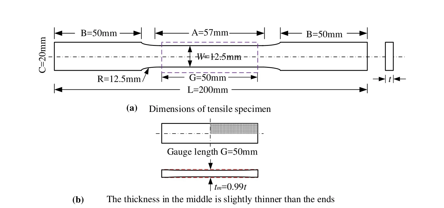
Figure 4:Geometry of tensile specimen

Figure 5:Equivalent plastic strain-Von Mises stress curves
5 Results and discussions
5.1 Element type effect
Solid and shell elements are used to study the splitting and curling behavior of the aluminum tube.Using the procedure given in the appendix,the predicted splitting and curling modes obtained from the solid and shell element are shown in Figs.6 and 7,respectively.The contours shown in these figures(top view of the tube)are the contact force between the rigid body and the metal tube.The corresponding load displacement responses are shown in Fig.9.For comparison purpose,the corresponding experimental results given in Ref.[Huang,Lu,and Yu(2002)]are shown in Figs.8 and 9.It is observed that the result for the tube pressed by α =75◦die is over-predicted.For this case,very high equivalent plastic strain is found in the curls,which exceeds the capability of the equivalent plastic strain stress curve given in section 4.3 to describe the material behavior accurately.In general,the predicted load displacement responses compare well with the experimental results.It is observed there are some differences in the load-displacement responses obtained from the shell and solid elements.These differences are introduced by the different assumptions and simplifications used in these elements.The advantage of using shell elements is its computational efficiency.The computation time for the solid element model is about 160h CPU time.If the element size is 0.5mm,it requires about 2560h(=160×24)CPU time.For the same tube,the computational demand of the shell element model is half of that of the solid finite element model.The shortcomings of the shell element for the present study are 1)The transverse shear is not well captured,see Appendix B:for detail,while,the present splitting crack is a complex mixed mode crack where transverse shear is important;2)The strip displays coupled bending and twisting deformation,which is a challenge for simple quad shell element to capture.The contact area obtained from the shell element as shown in Fig.7c does not capture the experimental observations well.The experimental contact area is indicated by the wear and tear in the strips as shown in Fig.8c[Huang,Lu,and Yu(2002)].As shown in Fig.7c(shell element),the contact areas are observed at the edges of the strips.However,in the experiment,contact area is also observed in the middle of the strips shown in Fig.8c.The contact area is well predicted by the solid element,which can be observed by comparing Fig.6 and Fig.8;and 3)The radius of the curling strip is relatively small compared with the thickness,which may invalidate the thin(or middle)thickness assumption in the shell element.This may also be a reason for the difference in the load-displacement response obtained from the shell and solid elements for the α =75◦case,where the ratio between the radius to thickness of the strip is about 4.For the mild steel tube,solid elements are used.
As shown in Figs.6 and 8,the edges of the strips are in contact with the rigid die.The hoop strain in the contact location may exceed the critical value.If only the strain criterion is used,these elements will be deleted as shown in Fig.10.To prevent deletion,the hoop stress criterion is proposed.

Figure 6:Predicted fracture patterns of aluminum tubes from solid element.
5.2 Results for steel tubes
The experimental and predicted load-displacement responses for the mild steel tube pressed by three different die angles α =45◦,60◦and 75◦are given in Fig.11.The corresponding splitting and curling patterns are shown in Figs.12 and 13,respectively.It is shown that the predicted responses compare well with the experiment result in general.Compared to the aluminum tube,the predicted results for mild steel are more accurate.It is observed from Fig.3a and 3b that the equivalent plastic strain-stress relation given in Fig.5 for the mild steel is better than that of the aluminum for characterizing the material behavior.This may be the reason for that the prediction for the mild steel is better than that of the aluminum tube.
For comparison purpose,the predicted and experimental average loads Favgand curl radius Ravgare summarized in Table 1.In general,the solid element gives a better prediction than that of the shell element.The predicted average load by using solid element is within 10%of the corresponding experimental result,except the aluminium tube pressed by α =75◦conical die.

Figure 7:Predicted fracture patterns of aluminum tubes from shell element.

Figure 8:Experimental fracture patterns of aluminum tubes,Ref.[Huang,Lu,and Yu(2002)].
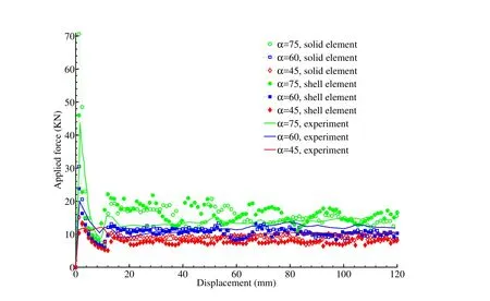
Figure 9:Comparison of the load-displacement responses obtained from solid and shell elements with the corresponding experimental results for aluminum tubes

Figure 10:Predicted fracture patterns,if only the strain criterion is used

Table 1:Comparisons between the predicted and experimental average loads and curl radius[Huang,Lu,and Yu(2002)].

Figure 11:Comparison of the predicted and experimental load-displacement responses for mild steel tubes.

Figure 12:Predicted fracture patterns of mild steel tubes from solid element

Figure 13:Experimental load-displacement responses for mild steel tubes,Ref.[Huang,Lu,and Yu(2002)]
5.3 Prediction of splitting crack number
An interesting question is that if there is no pre-saw cut,how many cracks will be formed.Atkins[Atkins(1987)]proposed an analytical method to predict the number of cracks by using bounding analysis associated with work dissipation rate.Theoretically,the hoop strain and stress are uniformly distributed.Infinite number of cracks will be predicted for any stress or strain based criterion.However,this does not happen in reality,because the real tube is not perfect.That is,the tube material properties are not ideally homogenous,and there must also be some variations in the geometries of the tube and shaped die as well.Numerically,even for a perfect tube,the determined stress and strain in the hoop direction of the tube are not uniform,especially when the explicit finite element method is used.A typical hoop stress variation is shown in Fig.14,where σhand σmare the hoop stress and the mean value of the hoop stress of the elements at the top of the tube. This result is obtained from the simulation of a perfect aluminum tube pressed by a α =60◦die by using J2plasticity implemented in ABAQUS/EXPLICIT.The stress variation is caused by the discrete FE model and associated numerical method.Therefore,the strain/stress variation and the imperfection of the tube should be considered in the finite element simulation,to bring results closer to agreement with reality.To predict the number of cracks,one element with ’weak’critical properties is used to model the imperfection.The critical strain and stress of the weak element should be less than(1−p)εcrand(1− p)σcr,respectively,to decrease the strain variation effect.p is the maximum relative deviation of the stress and strain,as shown in Fig.14 for an example.For simplicity,p=0.9 is used in the present prediction for the aluminum tube pressed by a α =60◦die.

Figure 14:A typical relative hoop stress variation,α =60◦.

Figure 15:Splitting and curling process,without initial saw-cut

Figure 16:Comparison of the predicted load-displacement responses for aluminum tubes with and without saw-cuts,α=60.
As the die presses down,the weak element will fail at first as shown in Fig.15a.The failure of this element will lead to stress redistribution and stress gradients,which then localizes the failure event.The next failure will happen at the element which satisfies the failure criterion given in Eq.(7).A new crack is shown in Fig.15b.It is observed from Fig.15b that the maximum hoop direction strain occurs at the element closest to the crack.Actually,there is a contact force acting at this element.If only the strain criterion is used,this element will be deleted,since the hoop strain(0.103 as shown in Fig.15b)exceeds the critical value(0.095).The stress criterion in Eq.(7)is used to prevent the deletion of this element.
As the die presses down,more cracks are initiated as shown in Fig.15c.It is observed that some cracks are closely spaced.The reason for the unexpected closely spaced cracks may be from the explicit finite element method and the discrete finite element model.In the explicit finite element method as introduced in section 2,the weak form is solved rather than the strong form equation for the system.It implies the stress equilibrium is not exactly satisfied.Furthermore,when crack is initiated(element deletion),there is a small disturbance and transients are introduced in the system.Physically,it takes time to achieve equilibrium.However,in the explicit finite element simulation,element deletion kicks in prior to attaining equilibrium.However,after a while,some of the closely spaced cracks stop growing.Eleven cracks are formed and stably propagated.A typical cracking,splitting and curling process is shown in Fig.15.The cracks are not uniformly spaced.The load-displacement response is given in Fig.16.Also shown in this figure is the predicted load-displacement response for the eight initial saw-cut tube.The average load for the eight saw-cut tube is higher than that of the tube without initial saw-cut.
6 Conclusions
In this paper,finite strain J2plasticity combined with a strain and stress based criterion is used to model the splitting and curling process of a circular tube crushed by different angled dies.The material model is implemented in the commercial finite element software ABAQUS/EXPLICIT through its user material subroutine VUMAT.Solid and shell elements are used to predict the splitting and curling behavior.It is found that the solid element is better than shell element for this problem.The splitting,curling and the load displacement responses predicted by using the solid elements are found to compare well with the corresponding experimental results.The present method is also used to predict the number of cracks for a ’perfect’tube pressed by shaped die,and,reasonable results are obtained.The proposed method can be extended to analyze the splitting and curling process of tubes subjected to dynamic impact.
Appendix A: Isotropic elasto-plasticity for the solid
The isotropic J2elastic-plastic theory,with associated hardening and Von Mises yield criterion is used to obtain the stress,which is required in Eq.(6).The method for solving the plasticity equations described in[Souza Neto,Peric,and Owen(2008)]is used in this study.This elastic-plastic behavior are described by the following set of equations,
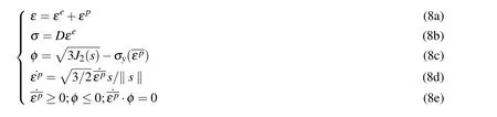


if φ<0,the material point is elastic or unloading.The elastic strain and stress are updated by Eqs.(9a)and(9b),respectively.Otherwise,some plastic strain is including in the strain increment.According to Eq.(8d),the plastic strain increment is,

and,the elastic strain is,


using the elastic constitutive law,the hydrostatic stress p and deviatoric stress s are:

It is found that the flow vector at the trial and updated stress state coincide by rewriting,Eq.(13b).

Rearranging Eq.(14),the deviatoric stress of the(n+1)thincrement is

substituting the above Eq.(15)into the yield surface equation Eq.(8c),leads to

The plasticity equations are reduced to the above single variable equation.The equivalent plastic strain increment in Eq.(16)can be solved by using Newton-Raphson iteration method.Once it is determined,the current stress,elastic and plastic strain and the equivalent plastic strain can be updated by using the following equations.

Appendix B:Isotropic elasto-plasticity for plane stress
Shell elements are used to study the splitting and curling of the metal tube.The inplane behavior of a shell element is composed of several plane stress elements.The number of plane stress elements correspond to the number of integration points in the thickness direction of the shell element,which is defined by the user[ABAQUS(2011)].Using the constant shear strain assumption,the transverse shear stress of the shell element is determined bykGγ,where,G,kandγare the shear modulus,shear stress correction factor and shear strain,respectively.The assumption of constant transverse shear is not accurate since the shear stress is known to be parabolic for simple plate geometries[Timoshenko and Goodier(1970)].To account for the inaccuracy in the shear strain,a shear stress correction factor is applied.For rectangular cross-section,kis 5/6.The transverse shear force will be automatically updated by ABAQUS/EXPLICIT,once the user provides theG,kand the thickness of the shell[ABAQUS(2011)].While the inplane stresses are updated by the user through the user material subroutine VUMAT.
The assumption of plane stress is that the stress components related to the thickness direction are assumed to be zero to first order,that is,

substituting the above relation into the three dimensional constitutive equation,E-q.(8b),we have

According to Eqs.(18)and(19),we have

Considering the plastic incompressibility assumption,yields

Therefore,the out of plane strain components can be completely defined by the in-plane values.In summary,the out of plane strain and stress are given as follows.

The in plane stress σ and strain ε are:σ =[σ11,σ22,σ12]Tand ε=[ε11,ε22,ε12]T.Substituting Eq.(22)into the three dimension plasticity equation,Eq.(8),the equations for plane stress isotropic plasticity are obtained.

A quadratic form yield surface is used to derive a single variable equation for solving the above equations,which is

Accordingly,the elastic strain,equivalent plastic strain and the yield surface function at the(n+1)thincrement are:


Substituting Eq.(26b)into the yield function,Eq.(25c),a single variable function is established as follows.

The equivalent plastic strain increment can be obtained by solving the above single variable equation.Subsequently,the stress,elastic strain and equivalent plastic strain are updated by using Eqs.(26b),(25a)and(25b),respectively.
It is observed that the transverse shear stresses are not included in theJ2 plasticity equations for plane stress,due to the assumptions used in the shell element.If the transverse shear is comparable with the in-plane stress,then solid elements are a better choice for modeling the tube.
Appendix C:Practical implementation in VUMAT
The plasticity model introduced in Appendix A:and Appendix B:is for small strain,small deformation problems.For the present tube,large deformation was observed in the experiment.The hypoelastic-plastic constitutive model is used in the present numerical study.However,by using the Green-Naghdi corotational stress formulation,which is used in ABAQUS/EXPLICIT,the numerical architecture of the small strain plasticity can be fully retained[Belytschko,Liu,and Moran(2000);ABAQUS(2011); Healy and Dodds Jr.(1992)].In the hypoelastic-plasticity model,the rate of deformation tensor is used in the constitutive model.The practical application of the hypoelastic-plastic constitutive model through ABAQUS/EXPLICIT user material subroutine VUMAT[ABAQUS(2011)]will be introduced in this section.The information at the beginning of a increment such as the stress,deformation gradient,and,strain increment are supplied by VUMAT.In addition,the user is allowed to use thestateNewin VUMAT to define any required parameters,for example,the equivalent plastic strain,and,the total elastic/plastic strain.ThestateNewat the beginning of the incrementstateOldis also supplied.The computation procedure is given as follows:
•1.Initial conditions:

•2.Elastic predictor:
Assign and compute the trial state variable

Check the yield condition by using Eq.(9e)for solid element and Eq.(24a)for shell element.Ifφtrial<0,the material is either remaining linear elastic or unloading,then go to step 4.Otherwise,go to step 3.
•3.Newton-Raphson radial return The incremental equivalent plastic strain for solid element is obtained by solving Eq.(16).While,for shell element,Eq.(27)is used instead.Subsequently,the stress and equivalent plastic strain are updated by Eq.(17)for the solid element.For shell element,Eqs.(26b)and(25a)are used.
•4.Updatestate Newand element deletion The total strain is updated throughstate Newin VUMAT bystate New=∆ε+state Old.Once the stress and strain components in the hoop direction(for the present tube)exceed their critical values,the material point is deleted by setting the corresponding state variable instate Newto be zero.For

where the elastic and plastic strain increments(∆εeand ∆εp)are byproducts of step 3.
The above procedure is coded into a VUMAT.Several examples are used to test the reliability of the plasticity code.The results obtained from the VUMAT code are found to compare very well with the ABAQUS implemented isotopical material model.
Alexander,J.(1960):An approximate analysis of the collapse of thin cylindrical shells under axial loading.Quarterly Journal of Mechanics and Applied Mathematics,vol.13,no.1,pp.10–15.
Abramowicz,W.;Jones,N.(1984):Dynamic axial crushing of circular tubes.
International Journal of Impact Engineering,vol.2,no.3,pp.263–281.
Atkins,A.(1987):On the number of cracks in the axial splitting of ductile metal tubes.International Journal of Mechanical Sciences,vol.29,no.2,pp.115–121.
ABAQUS(2011):ABAQUS documentation.Version 6.11.
Appliedcom(2015):Coefficients of friction.URL http://web.applied.com/assets/attachments/492ACC9E-E5C2-2D43-0B8CCDA72ACE3361.pdf
Bathe,K.(1996):Finite element procedure.Prentice Hall,Englewood Cliffs,New Jersey.
Bathe,K.-J.;Walczak,J.;Guillermin,O.;Bouzinov,P.;Chen,H.-Y.(1999):Advances in crush analysis.Computers and Structures,vol.72,no.1,pp.31–47.
Belytschko,T.;Black,T.(1999):Elastic crack growth in finite elements with minimal remeshing.International Journal for Numerical Methods in Engineering,vol.45,no.5,pp.601–620.
Belytschko,T.;Liu,W.;Moran,B.(2000):Nonlinear finite elements for continua and strcutures.John Wiley and Sons,LTD.
Bai,Y.;Wierzbicki,T.(2010):Application of extended mohr-coulomb criterion to ductile fracture.International Journal of Fracture,vol.161,no.1,pp.1–20.shell elements,the strain increment in the thickness direction is required to be updated by using the following equations.If the material is elastic or unloading,
Boyce,B.;Kramer,S.;Fang,H.et al.(2014):The sandia fracture challenge:Blind round robin predictions of ductile tearing.International Journal of Fracture,vol.186,no.1-2,pp.5–68.
D’Mello,R.;Guntupalli,S.;Hansen,L.;Waas,A.(2012):Dynamic axial crush response of circular cell honeycombs.Proceedings of the Royal Society A:Mathematical,Physical and Engineering Sciences,vol.468,no.2146,pp.2981–3005.Dong,L.;Atluri,S.N.(2013):Fracture and Fatigue Analyses:SGBEM-FEM or XFEM?Part 2:3D Solids.CMES:Computer Modeling in Engineering&Sciences,vol.90,no.5,pp.379–413.
Gurson,A.(1977):Continuum theory of ductile rupture by void nucleation and growth:Part 1-yield criteria and flow rules for porous ductile media.Journal of Engineering Materials and Technology,Transactions of the ASME,99 Ser H(1),pp.2–15.
Guillow,S.;Lu,G.;Grzebieta,R.(2001):Quasi-static axial compression of thinwalled circular aluminium tubes.International Journal of Mechanical Sciences,vol.43,no.9,pp.2103–2123.
Galib,D.Al,Limam,A.(2004):Experimental and numerical investigation of static and dynamic axial crushing of circular aluminum tubes.Thin-Walled Structures,vol.42,no.8,pp.1103–1137.
Gross,A.;Ravi-Chandar,K.(2014):Prediction of ductile failure using a local strain-to-failure criterion.International Journal of Fracture,vol.186,no.1-2,pp.69–91.
Healy,B.;Dodds,Jr.,R.(1992):A large strain plasticity model for implicit finite element analyses.Computational Mechanics,vol.9,no.2,pp.95–112.
Hanssen,A.;Langseth,M.;Hopperstad,O.(2000):Static and dynamic crushing of circular aluminum extrusions with aluminum foam filler.International Journal of Impact Engineering,vol.24,no.5,pp.475–507.
Huang,X.;Lu,G.;Yu,T.(2002):On the axial splitting and curling of circular metal tubes.International Journal of Mechanical Sciences,vol.44,no.11,pp.2369–2391.
Han,Z-D.;Atluri,S.N.(2014):Eshel by Stress Tensor T:a Variety of Conservation Laws for T in Finite Deformation Anisotropic Hyperelastic Solid&Defect Mechanics,and the MLPG-Eshelby Method in Computational Finite Deformation Solid Mechanics-Part I.CMES:Computer Modeling in Engineering&Sciences,vol.97,no.1,pp.1–34.
Han,Z-D.;Atluri,S.N.(2014):On the(Meshless Local Petrov-Galerkin)MLPGEshelby Method in Computational Finite Deformation Solid Mechanics-Part II.CMES:Computer Modeling in Engineering&Sciences,vol.97,no.3,pp.199–237.
Joun,M.;Choi,I.;Eom,J.;Lee,M.(2007):Finite element analysis of tensile testing with emphasis on necking.Computational Materials Science,vol.41,no.1,pp.63–69.
Kamaya,M.;Kawakubo,M.(2011):A procedure for determining the true stressstrain curve over a large range of strains using digital image correlation and finite element analysis.Mechanics of Materials,vol.43,no.5,pp.243–253.
Lu,G.;Yu,T.(2003):Energy Absorption of Structures and Materials.CRC Press.Woodhead Publishing Limited.Cambridge England.
Nahshon,K.;Miraglia,M.;Cruce,J.;Defrese,R.;Moyer,E.(2014):Prediction of the sandia fracture challenge using a shear modified porous plasticity model.International Journal of Fracture,vol.186,no.1-2,pp.93–105.
Pack,K.;Luo,M.;Wierzbicki,T.(2014):Sandia fracture challenge:Blind prediction and full calibration to enhance fracture predictability.International Journal of Fracture,vol.186,no.1-2,pp.155–175.
Reddy,T.;Reid,S.(1986):Axial splitting of circular metal tubes.International Journal of Mechanical Sciences,vol.28,no.2,pp.111–131.
Reid,S.(1993):Plastic deformation mechanisms in axially compressed metal tubes used as impact energy absorbers.International Journal of Mechanical Sciences,vol.35,no.12,pp.1035–1052.
Silling,S.A.(2000):Reformulation of Elasticity Theory for Discontinuities and Long-Range Forces.Journal of the Mechanics and Physics of Solids,vol.48,pp.175–209.
Souza Neto,E.d.;Peric,D.;Owen,D.(2008):Computational method for plasticity:theory and applications.John Wiley and Sons,Ltd,Publication.
Timoshenko,S.;Goodier,J.(1970):Theory of Elasticity,3rd Edition.McGraw-Hillp International Book Company.
Tvergaard,V.;Needleman,A.(1984):Analysis of the cup-cone fracture in a round tensile bar.Acta Metallurgica,vol.32,no.1,pp.157–169.
Tarigopula,V.;Langseth,M.;Hopperstad,O.;Clausen,A.(2006):Axial crushing of thin-walled high-strength steel sections.International Journal of Impact Engineering,vol.32,no.5,pp.847–882.
Wierzbicki,T.;Bao,Y.;Lee,Y.-W.;Bai,Y.(2005):Calibration and evaluation of seven fracture models.International Journal of Mechanical Sciences,vol.47,(4-5 SPEC.ISS.),pp.719–743.
Xue,L.(2007):Damage accumulation and fracture initiation in uncracked ductilep solids subject to triaxial loading.International Journal of Solids and Structures,vol.44,no.16,pp.5163–5181.
1University of Michigan,Ann Arbor,MI,USA.
2University of Washington,Seattle,WA,USA.