Modular Model Library for Energy System in Lunar Vehicle
Chen Chang,Su Shaohuiand Chen Guojin
Modular Model Library for Energy System in Lunar Vehicle
Chen Chang1,Su Shaohui1and Chen Guojin1
For modeling and simulation of energy system in lunar vehicle,there are many special purpose tools along with their models,such as PSIM,EMTP/ATP,could be used.But the models in these tools lack of flexibility and are not open to the end-user.Models developed in one tool can’t be conveniently used in others because of the barriers among these simulators.Usually these models are expressed in an explicit state-space form and their topology gets lost and future extension and reuse of the model is almost impossible.In order to solve those problems,a flexible and extensible energy system model library for lunar vehicle is constructed in this study,based on the Modelica,by the level progressive modeling strategy.Each model in this library is expressed in equation form.It supports reuse of knowledge on different granularities:physical phenomenon,unit model and system model.It is an interface-friendly,accurate,fast PC-based and easily reusable simulating tool which enables end-user to customize and extend the framework to add new functionality or adapt the simulation behavior as required.It also allows new models to be composed programmatically or graphically to form more complex models by invoking the existing components.A solar battery and storage battery model is simulated and the results agree well with the experimental data.At last,a simple energy system model for lunar vehicle is built and calculated using the library and it shows that the level progressive modeling strategy is effective,the framework of the library is reasonable.
energy system,lunar vehicle,level progressive modeling strategy,model reuse,Modelica
1 Introduction
Energy system,which is a key sub-system of lunar vehicle,provides the power for other sub-systems,such as measurement and control sub-system,locomotion subsystem,thermal control sub-system,integrated electronic sub-system and so on.Itis consisted of solar cell,storage battery,nuclear battery,DC-DC converter,DC-AC convertor,etc.Up to present,a number of special purpose simulators(proprietary simulation tools,such as PSIM,EMTP/ATP)along with their comprehensive model libraries can be used for modelling and simulation of energy system.Kulaksiz et al.built the model of stand-alone PV system and researched a generic MPPT(Maximum Power Point Tracking)algorithm for the photovoltaic system with induction motor drive based on PSIM[Kulaksiz and Akkaya(2012)].Lin Ye et al.model a dynamic model for a hybrid wind/solar/hydro micro grid with EMTP/ATP[Ye,Sun,Song,and Li(2012)].
In most of these simulators,the energy system component is commonly described as a black box which users just know how to use but don’t know the details of it.So it is very difficult to modify an existing model and introduce a new one in these simulators.And the worse is the models developed in one tool cannot be easily used in another one because of the different model description,translation,data organization etc.among these simulators.Although considerable engineering knowledge has been accumulated in various kinds of tools,it is difficult to be shared with each other.It is the consequences:huge amounts of work were repeated again and again just because of the barrier between the different simulation platforms.
There are also some general simulation platforms,such as Matlab/Simulink,could be used to model the energy system in lunar vehicle.For example,Stephan Buller et al.modelled an impedance-based non-linear dynamic battery for vehicle using Matlab/Simulink[Buller,Thele,Karden,and Doncker(2003)].In most of these platforms,the model is usually expressed in an explicit form and iterative process of model solution has to be given out if the explicit expression could not be found.So the computational order of the operations during the simulation must be considered by the modeller.Consequently,the modelling efficiency is low,the topology of the system gets lost,and any future extension and reuse of the mode are tedious.
This paper presents a modular model library for energy system of lunar vehicle based on Modelica modelling language.The Modelica language is object-oriented,non-causal,and suitable for physical modelling and the tool handles the symbolic organization of all the ordinary differential and algebraic equations,and solves them numerically[Tiller(2001)]and its latest version of specification is 3.3[Association(2014)].It supports encapsulation,composition and inheritance facilitating model development and update.Elementary models of physical elements are defined in the declarative expression by their constitutive physical principles,and their interface with the outer world is described by physical connectors without any implied causality,rather than by writing assignments relating inputs to outputs.This makes the description of physical systems much more flexible and natural than it is possible with causal or block-oriented modelling languages,or by directly writ-ing simulation code using procedural languages such as C or FORTRAN.Using the object-oriented modelling language Modelica one can build complex model libraries with the basic principles,i.e.,physical laws,energy-balance equations,and such model classes could be reused in different configures easily.This approach provides easier future adaptations and extensions in complex systems[Chen,Ding,and Chen(2013)].Because of the above advantages,Modelica has been widely applied in the modelling of physical system in lots of domain,such as building energy system[Anton and Borut(2009)]vehicle[Deuring,Gerl,and Wilhelm(2011);Andreasson(2011)],craft[Pulecchi,Casella,and Lovera(2010)],machine[Dressler,Schiffer,and Robertsson(2009)],fluid system[Viel(2011);Casella,Sielemanny,and Savoldelli(2011)],control system[Baur,Otter,and Thiele(2009)],education[Borut and Anton(2013)]and so on.
The Modelica language includes graphical annotations,which allow to use graphical user interfaces(such as the one provided by the tool MWorks[Zhou,Chen,and Wu(2006)],Dymola[Dassault Systems(2015)],OpenModelica[OpenModelica(2015)]or SimulationX[ITI(2015)]and so on)to select components from a library,drag them into a diagram,connect them,and set their parameters,thus making the process of model development highly intuitive for end users.In order to minimize the development time,Modelica allows the definition and reuse of intermediate elements,common to more models of the same component.The key feature to extensive model reusability and flexibility is given by the extensive exploitation of two Modelica constructs:extend and redeclare,and their associated keywords:partial and replaceable.The partial/extends binomial permits the extension of partial(i.e.,partial-complete)models into complete,fully detailed models.The emphasis of this paper are exploring the level progressive modelling strategy for energy system and constructing a modular energy system model library,which contains kinds of battery,converter and so on.In section two,the level progressive modelling strategy and the structure of energy system library(ESL)will be presented,aiming at providing a framework of energy library and some kinds of usual models.Implementation of the model in language Modelica will be presented in detail in section three.In section four,some examples will be presented and their simulation results will be provided and compared with the experimental data.
2 Structuring idea of library
2.1 Level progressive modelling strategy
A physical system model development has followed the top-down design approach,which applies the method of functional decomposition to establish the model structure.This method has been successfully applied in many physical engineering domains,but it fails to reflect the real world.Because the components model of system is constructed following the components’function but not the topology of system with top-down approach,the system model could not reflect the real physical system and the model is hardly reused on another simulation plat.Besides the top-down method,there is another method that with it the physical system is decomposed into elementary mathematical operation block,such as integration block,add block,multiply block in Simulink.A block has specific relation between variables of the input and the output.It is just a mathematical model but not physical model and loses its physical significance.
As mentioned in section one,Modelica supports the object-oriented modelling of physical system.Each model is considered as physical object which is a capsule contains its attributes,physical behaviours,and interfaces using for information interaction with outside world.And a model could connect another model in a nature way which keeps the topological structure consistent with real physical world.The energy system is decomposed with this method,as shown in Fig.1.Energy system S could be expressed as two sets with proper topology assumption.One is sub-system S1which constitutes the S and another is R1which means the relation between each sub-system in S1.

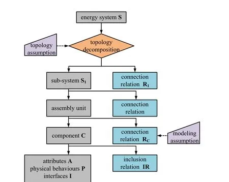
Figure 1:Decomposition of energy system with object-oriented method

s1jmeans a sub-system of energy system and s1k.athe interface a belong to subsystem s1k.(s1k.a,s1l.b)means that the interface a connects to the interface b which belongs to s1l.Follow the method,the sub-system could be decomposed into the component set C and the connection relationship RCbetween each component level by level.Further,the component could be divided in to attribute set A,basic physical behaviours set P,interfaces set I and the inclusion relation set IR.
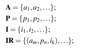
Where,ammeans one of attributes in a component,such as the parameter,variable.pnmeans the basic physical phenomenon.For example,resistance,capacitance and inductance have a common physical phenomenon that is their terminal voltage equal to the potential difference between positive electrode and negative electrode.ikmeans the interfaces contained in a component.For instance,a resistance have two electrodes:positive electrode and negative electrode mentioned above.
As a result,the different levels’models:from basic physical phenomenon models,over physical unit modes,up to system models could be reused flexibly in the process of constructing a new model.And the different level’s model is corresponding with the real physical system.
The process of system modelling is contrary to that of system decomposing.First of all,the part-complete model,like the attributes and basic physical behaviours,is constructed.It’s worth noting that the part-complete model is not complete to instantiate.So it is used as a base class for inheritance and extension.The language modelica provides the prefix partial to describe the part-complete model as shown in the following code.A part-complete model named TwoRode,which has two electrode interface,two variables and three physical equations,is built.
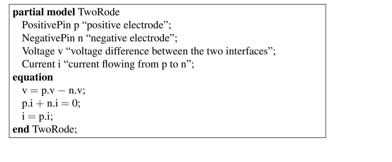
partial model TwoRode PositivePin p “positive electrode”;NegativePin n “negative electrode”;Voltage v “voltage difference between the two interfaces”;Current i“current flowing from p to n”;equation v=p.v-n.v;p.i+n.i=0;i=p.i;end TwoRode;
Model TwoRode provides the common code that could be inherited to construct a complete model,such as resistance model shown in the following code.The parameter R and the ohm law equation are added in the model.The capacitance,inductance and the other modelcould be built with the extending mechanism.Finally,the system model could be constructed level by level according to the topology of real system.

model Resistance extends TwoRode;parameter resistance R=1;equation v=i*R;end Resistance;
2.2 Structure of the model library
With the level progressive modelling method mentioned above and considering the maximum reuse of codes in the library,the energy system could be decomposed into several sub-libraries.Each sub-library consists of various component models that were created through inheriting and expanding the basic part-complete models.Fig.2presents the architecture of the library which is consisted of five sub-libraries.
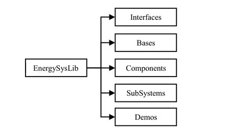
Figure 2:Top-level structure of energy system model library
·Interfaces:the connectors among the components,like connect PositivePin mentioned in the code of part-complete model TwoRode,are defined here.
·Bases:it is a sub-package of the part-complete model like the TwoRode which will be presented in section 3.2.These models are the basic blocks for building complete physical components.
·Components:a sub-package consists of complete models(like theResistancemodel mentioned in the former section)that used to construct system model.It is a key sub-package which accounts about 60%of all colds in the whole library.
·SubSystems:a package includes storage battery,nuclear battery,DC-DC converter,DC-AC convertor models.
·Demos:some typical examples of energy system model for lunar vehicle are given here.
This library provides a flexible and extensible resource that could be used to compose new energy system models for lunar vehicle graphically or programmatically,to inspect and edit the existing models,and to simulate the display execution results.It also provides port-compatible software components that users can combine to form a complex energy system models according to the real physical system.
3Common Models
3.1 Interface
Modelica provides a special-purpose class named connectorwhich defines the variables of the model shared with other models,without implied causality,rather than by writing assignments relating inputs to outputs.In this way the connections can be thought of as one of the key features of object oriented modeling,enabling effective model reuse.There are two types of built-in variables:potential variable,flow variable declared with no prefix,the prefixesflow.The potential and flow variables follow the Generalized Kirchhoff’s law,like the voltage and current in the electronic field.For instance,the connectorPositivePinhas two variablesvandithat represent potential and current respectively,as shown in the following codes.

connector PositivePin SI.Potential v “Potential at the pin”;SI.Current i“Current flowing into the pin”;end PositivePin;
Fig.3 shows the connection of three components that has the connectorPostivePin.All the potential in each connector must be equalized while the sum of all the current should be zeros.


Figure 3:Connecting of three electrical components
The two equations above originating from the connection definitions will be generated and added to the equation system of the model automatically when the model is compiled.Besides thePostivePin,there are several different connectors available in the library,such as sun light connector for the solar cell model.There is also some connector combinations were introduced and classified into the library.For example,there is one positive electrode and one negative electrode in the resistance model.So the two-interface mode namedTwoPin,which has no equation in its codes,was introduced.
3.2 Partial model
Partial model is a kind of part-complete component which abstracts the common character shared by a group of component models that have some common properties and behaviours or the same structure.It is a basic section of the component model sub-library.For example,the resistance,capacitance and inductance that could be considered as models include two electrode interfaces(one for positive pole and the other for negative pole)as presented in section 2.1.They have the common properties and behaviours as follow.Their terminal voltage equals to the electric potential difference between the positive pole and the negative pole while their current equals to the current of positive pole.The current flowing in the component is positive while that flowing out is negative and the sum of them is zero.

Where,vis the terminal voltage;ithe current flowing through the model.So the partial modelTwoRodewas built to describe the properties and physical behaviours shared by these two electrode models and other similar models as mentioned in section 2.1.
At the beginning of the codes,the prefix “partial”means modelTwoRodeis semicomplete.When a higher level model like resistance is wanted to be introduced,TwoRodewill beinherited and expanded,as shown in section 2.1.So the embedded engineering knowledge could be reused on physical behavioural level but not only on model level.In the “equation”region,the behaviours described in Eqs.(3-5)are coded in non-causal expression.
3.3 Component model
Each component model is the basic complete model,which reflects the real physical component like resistance,could be used to construct the complicated sub-system or high level system.In this section,a conventional sub-system solar battery will be taken as an example to illustrate how to decompose a complex system into some components model and the process of building a component model.
For the technical application,a solar battery is widely modelled in an equivalent circuit form,like the double-exponential equivalent circuit[Gow and Manning(1999)]shown in Fig.4.The circuit consists of one DC power sourceIph,two diodesD1andD2,a series resistorRSand a parallel resistanceRsh.The variableIis the current of solar battery whileuis terminal voltage.
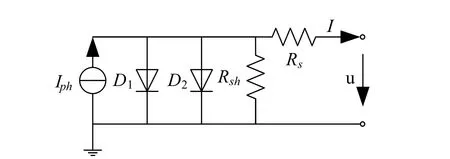
Figure 4:Solar battery equivalent circuit model
According to the level progressive modelling strategy,the circuit model could be divided into the model set which contains DC power source model,diode model,resistor model and the set of their connection relationship.

Whereaandbis the interfaces connecting to the surroundings.And the behaviour of elements in themodelsetSBcould be described as follow.


Where,the variableIphis the photo-generated current,A.ID1the saturation current from diffusion mechanism,A.ID2the saturation current from gap layer,A.Athe quality factor of diode.Rsthe value of series resistor,Ω.Rshthe value of parallel resistor,Ω.k,boltzmann constant,k=1.38e-23J/K.Eg,band-gap,=1.12eV.T,environment temperature,K.G,illuminance,W/m2.The parametersIph0,KD1,KD2,RS0,RSh0should be demarcated by the analytical method mostly according to the experimental data.The analytical method needs to choose several points of the experimental data that resulted in low accuracy of parameters.The numerical calibration method is introduced to obtain the high-precision parameters and reduce the error caused by the selection of experimenter.
Following the decomposition of circuit model,the basic element could be built by inheriting and expending the partial model.Take the diode as an example.It has two electrode and one signal port which is used for obtain the temperature of surroundings as shown in the following model code.
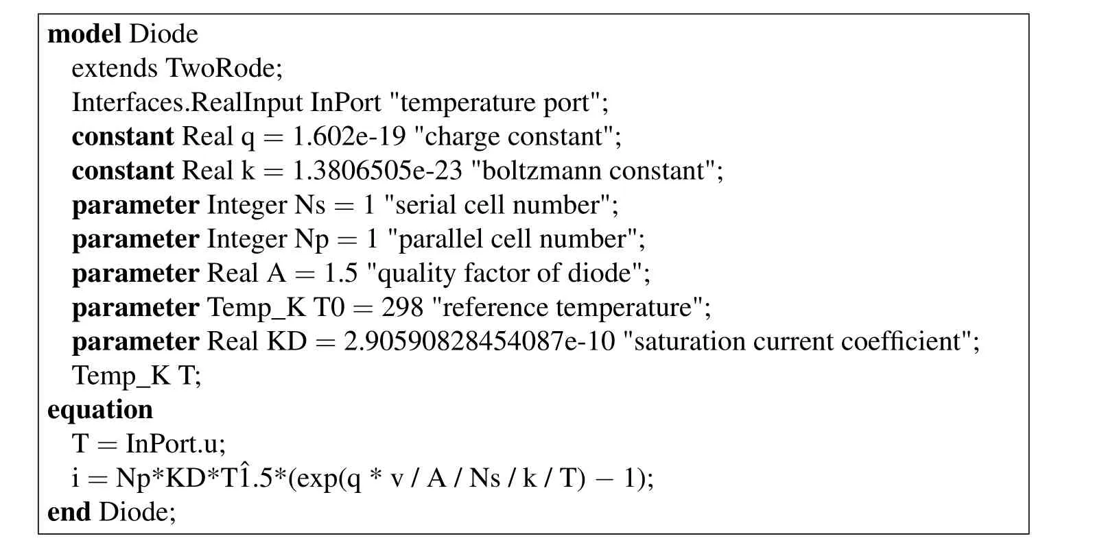
model Diode extends TwoRode;Interfaces.RealInput InPort"temperature port";constant Real q=1.602e-19"charge constant";constant Real k=1.3806505e-23"boltzmann constant";parameter Integer Ns=1"serial cell number";parameter Integer Np=1"parallel cell number";parameter Real A=1.5"quality factor of diode";parameter Temp_K T0=298"reference temperature";parameter Real KD=2.90590828454087e-10"saturation current coefficient";Temp_K T;equation T=InPort.u;i=Np*KD*Tˆ1.5*(exp(q*v/A/Ns/k/T)-1);end Diode;
The partial modeltwoRodeis extended and some parameters,variables,and equations and interfaces are added.The Real inputInPortare used for exchanging environment information with surroundings,such as the temperature.There are three types of variable in the codes.The variable with prefix “constant”means that the variable is a physical constant,which is invariable.The variable with prefix“parameter”means that the variable is a parameter,which could be redefined before simulation.But it could not be changed in the process of simulation.The variable with no prefix,like T in the code,means that the variable is time varying.In the zone “equation”,the behaviour of diode is added according to the Eq.(8).At last,the model is encapsulated and graphical.According to the parameter declarations,a parameter table will be created automatically by the Modelica-supported modelling and simulation platform,as shown in Fig.5.The end-user could assignment the parameter according to the physical component when the model is used in a high-level system models.Following the methods above,the other modular modes could be built.

Figure 5:Parameter table of diode model
3.4 Sub-system model
According to the topological relationship between each component,the equivalent circuit model of solar battery could be established language by combining the component models based on the object oriented technology.The Fig.6 shows its encapsulation and forming framework.The element bus is the input port of temperature of surroundings and the solar luminance.
Based on the modelling flow mentioned from section 3.2 to section 3.4,the other sub-systems of energy system in lunar vehicle were constructed,as shown in Fig.7.There are several types of storage battery model,four types of solar battery model,and some different DC-DC convertor models and so on.
When a sub-system model is needed to be instantiated,the value of its parameters should be assigned to guarantee its accuracy.At present,the parameters of model could be almost calibrated by the analytical method,like the storage battery model’s calibration and solar battery model’s calibration[Dong Guan SuperB Solar Co.LTD.(2015)].The analytical method needs to choose several points of the experimental data artificially that resulted in low accuracy of parameters.Taking least square method for the reference,a numerical calibration method is introduced to obtain the high-precision parameters in this article.Its detailed process is shown in Fig.8.An example for the comparison of result between analytical and numerical method will be presented in section 4.1.
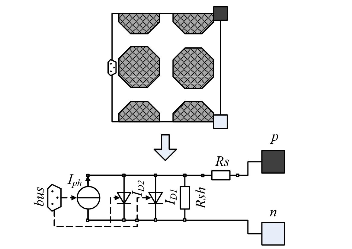
Figure 6:Encapsulation and construction of solar cell model
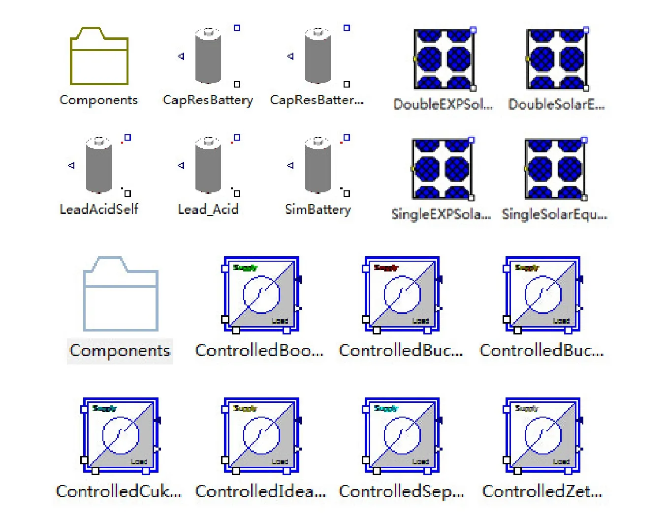
Figure 7:Some significant models for energy system
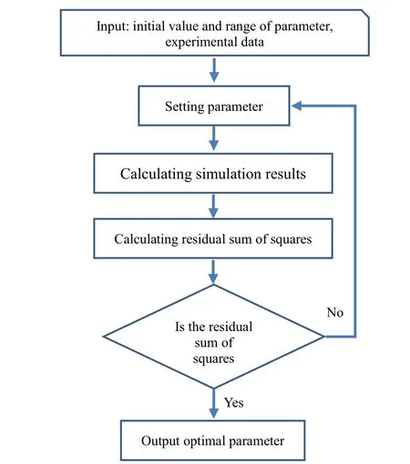
Figure 8:Process of numerical parameter calibration
4 Simulation examples
4.1 Solar battery model
In this section,a solar battery test model is constructed using the energy system library graphically and its characteristics is simulated.It cantains components Enviroment,SolarBattery,PowerSensor,Signaralvoltage,and Ramp,as shown in Fig.9.The model Enviroment provides the information about the enviroment,such as the temperature and the illumination of sunlight while models Signaralvoltage and Ramp provide the voltage load.The specification of solar battery is CKPV-080W-5M36 from Dongguan Superb Solar Co.,LTD[Dong Guan SuperB Solar Co.LTD.(2015)].Its electrical characteristics are listed in Tab.1.Tab.2 lists the the parameters Iph0,KD1,KD2,RS0,RSh0that calibrated by analytical and numerical method respectively.
The comparison of results between analytical,numerical method and experiment is shown in Fig.10.When the terminal voltage is smaller than the voltage at the maximum power point(MPP),the I-V curve of solar battery are matched very well.But the terminal voltage is bigger than the voltage at MPP,the error of result with analytical methods is more than that of numerical methods.The maximum error of result with analytical methods is 1.07A while the relative mean error is 21.86%.Compared with the results of analysis methods,the numerical method could ensure that the characteristic curve of solar cell model keep goodness of fit in the whole range of terminal voltage with the experimental data.The result of test case shows that the relative mean error of I-V curve of solar cell model is 1.67%.
4.2 Storage battery model

Figure 9:Solar battery test model
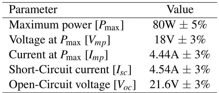
Table 1:Electrical characteristics of CKPV-080W-5M36

Table 2:Calibration parameters using analytical and numerical method
There are many kinds of model,like simple idealized batterymodel,R-Cequivalent circuit model[Einhorn,Conte,Kral,Fleig,and Permann(2010)]and Shepherd’s model[Shepherd(1965)],could be used to describe the storage battery.In theESL,seven types of different storage battery model were implemented that they could be used to imitate the lead-acid storage battery,NI-MH battery,lithium battery and so on.Fig.11 demonstrates a simple NI-MH battery discharge model,which consists of a battery,a signal current source,a constant input and a power sensor,for the HHR650D battery from Panasonic.The specification of HHR650D could be found in reference[Panasonic Co.LTD.(2005)].
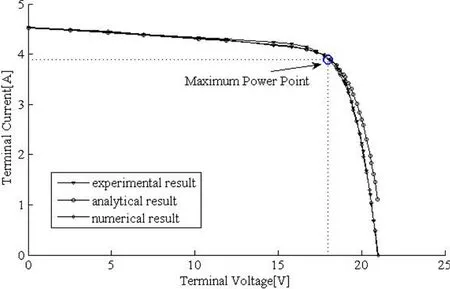
Figure 10:Comparison of results between analytical,numerical method and experiment
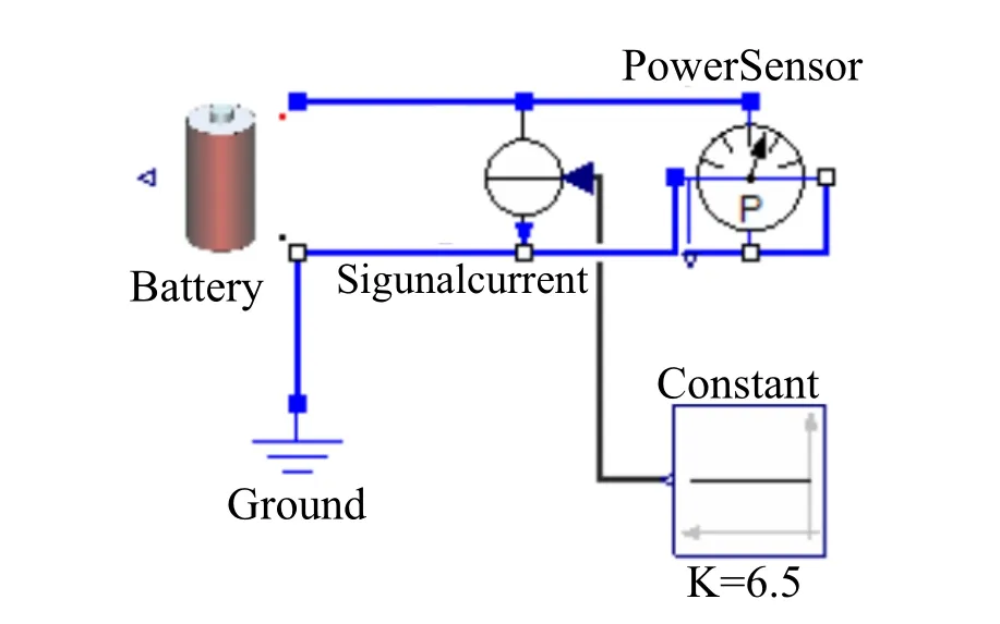
Figure 11:Battery discharge model for HHR650D from Panasonic
Fig.12 represents the comparison of the battery discharge curves between simulation and experiment,under the condition of discharge current 6.5A,13A,32.5A.The solid line represents the simulation results while the dotted line the experiment results.And the mean error of the simulation curves is 0.03V.
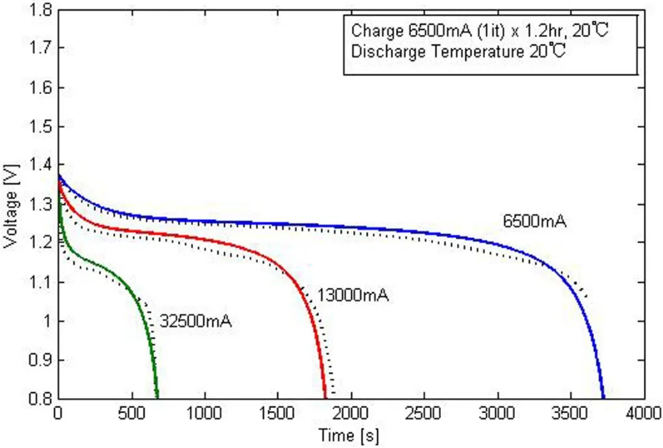
Figure 12:Battery discharge curves between simulation and experiment
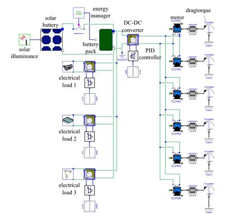
Figure 13:Simple energy supply system model for lunar vehicle in MWorks
4.3 Simple energy system model for lunar vehicle
In this section,a simple energy supply system model,which is consists of a storage battery pile,a solar battery,an energy system manager,several DC-DC converters,several controllers for DC-DC converter,and some electrical load,is established graphically using the ESL,as shown in Fig.13.The six permanent magnet DC motors(DCPM)are used to drive the tires of the lunar vehicle while the drag torque of a tire is instead of the modeldragtorquesimplistically.The electrical loads,likeelectrical load 1,2,3in Fig.13,consisted of a resistance,an inductance and a capacitance could be used to imitate the power and the dynamic response of the real electrical components.The energy manager is used to control the charging and discharging of the battery pack according to SOC of battery package.The DC-DC converters are used to be transforming the voltage of battery pack to the voltage required by the electrical loads.The battery pack consists of forty battery cells mentioned in section 4.2 that arrange in two parallels and twenty series.
After the model being built,each of these components is shown on a model window whose properties and parameters could be modified and then the model could be translated and simulated.When the simulation finishes successfully,the results are available.All variables for each component in the simulation model could be exported and plotted.Fig.14 shows the changing SOC of battery pack against time.Fig.15 shows the voltage of permanent magnet DC motors and its value is controlled by the DC-DC converter and the PID controller.
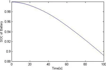
Figure 14:SOC of battery pack
5 Conclusions
In this paper,we tried to utilize the multidisciplinary physical modeling language Modelica to build an object-oriented modular energy system library in the Modelicasupported tool MWorks.The aim is to explore the framework and implement of energy system models based on the object-oriented technology and to provide an energy system library.The library mainly includes solar cell models,storage battery models,DC-DC converter models,etc.that mostly used in lunar vehicle.It supports the reuse of knowledge on different granularities:physical phenomenon,unit model and system model based on the proposed level progressive modeling strategy.
The library can be extended and customized to meet future application requirement.The layered modular components in this library could be easily modified and extended because the flame of model is constructed.New components could be introduced conveniently according to the actual requirements.A solar battery and storage battery model was simulated and the results agreed well with the experimental data.And a simple energy system model for lunar vehicle could be built rapidly by calling the components existed in the library as the example mentioned in section 3.It shows that the level progressive modeling strategy is effective;the framework of the library is reasonable;the models in the library are accurate.
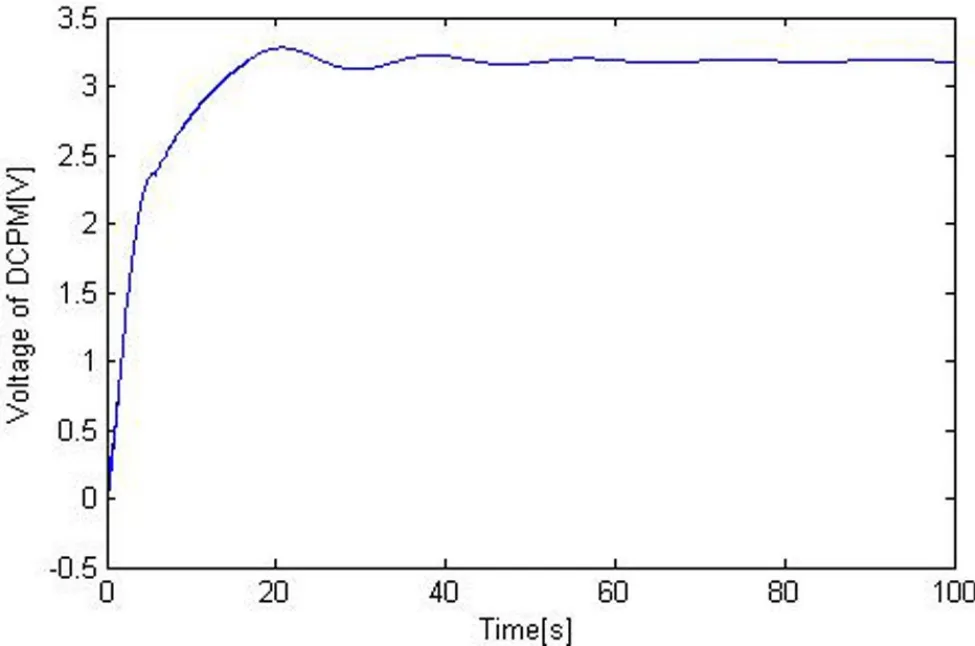
Figure 15:Voltage of permanent magnet DC motors
Acknowledgement:The paper is supported by the National Natural Science Foundation of China(Grant No.51405117,51475129).
Ahmet,A.K.;Ramazan,A.(2012):A genetic algorithm optimized ANN-based MPPT algorithm for a stand-alone PV system with induction motor drive.SolarEnergy,vol.86,pp.2366-2375.
Lin,Y.Hai,B.;Xu,R.S.;Li,C.L.(2012):Dynamic modeling of a hybrid wind/solar/hydro microgrid in EMTP/ATP.Renewable Energy,vol.39,pp.96-106.Stephan,B.;Marc,T.;Eckhard,K.;Rik,W.D.(2003):Impedance-based nonlinear dynamic battery modeling for automotive applications.Journal of Power Sources,vol.113,pp.422-430.
Tiller,M.(2001):Introduction to Physical Modeling with Modelica.Massachhusetts USA:Kluwer Adademic Publishers.
Modelica Association.(2014):Modelica-A Unified Object-Oriented Language for Systems Modeling Language Specification(Version 3.3 Revision 1),https://modelica.org/documents/ModelicaSpec33Revision1.pdf.
Chen,C.;Ding,J.;Chen,L.(2013):Object-oriented Modular Modelica Library for Distillation.Chinese Journal of Chemical Engineering,vol.21,no.6,pp.600-610.
Anton,S.;Borut,Z.(2009):Modelling thermal processes in buildings using an object-oriented approach and Modelica.Simulation Modelling Practice and Theory,vol.17,pp.1143-1159.
Deuring,A.;Gerl,J.;Wilhelm,H.(2009):Multi-Domain Vehicle Dynamics Simulation in Dymola.Proceedings of the 8th International Modelica Conference.Linköping,Sweden:Linköping University Electronic Press,pp.13-17.
Andreasson,J.(2011):The Vehicle Dynamics Library:New Concepts and New Fields of Application.Proceedings of the 8th International Modelica Conference.Linköping,Sweden:Linköping University Electronic Press,pp.414-420.
Pulecchi,T.;Casella,F.;Lovera,M.(2010):Object-oriented modelling for spacecraft dynamics:Tools and applications.Simulation Modelling Practice and Theory,vol.18,pp.63-86.
Dressler,I.;Schiffer,J.;Robertsson,A.(2009):Modeling and Control of a Parallel Robot Using Modelica.Proceedings of the 7th International Modelica Conference.Linköping,Sweden:Linköping University Electronic Press,pp.261-269.
Viel,A.(2011):Strong Coupling of Modelica System-Level Models with Detailed CFD Models for Transient Simulation of Hydraulic Components in their Surrounding Environment.Proceedings of the 8th International Modelica Conference.Linköping,Sweden:Linköping University Electronic Press,pp.256-265.
Casella,F.;Sielemanny,M.;Savoldelli,L.(2011):Steady-state initialization of object-oriented thermo-fluid models by homotopy methods.Proceedings of the8th International Modelica Conference.Linköping,Sweden:Linköping University Electronic Press,pp.86-96.
Baur,M.;Otter,M.;Thiele,B.(2009):Modelica Libraries for Linear Control Systems.Proceedings of the 7th International Modelica Conference.Linköping,Sweden:Linköping University Electronic Press,pp.593-602.
Borut,Z.;Anton,S.(2013):Computer-aided physical multi-domain modelling:Some experiences from education and industrial applications.Simulation Modelling Practice and Theory,vol.33,pp.45-67.
Zhou,F.;Chen,L.;Wu,Y.(2006):MWorks:a Modern IDE for Modeling and Simulation of Multi-domain Physical System Based on Modelica.5th International Modelica Conference,Vienna,Austria,pp.725-731.
Dassult Systems.(2015):http://www.3ds.com/products-services/catia/capabilities/modelica-systems-simulation-info/dymola.
OpenModelica.(2015):https://openmodelica.org/.
ITI.(2015):http://www.simulationx.com/.
Gow,J.A.;Manning,C.D.(1999):Development of a Photovoltaic Array Model for Use in Power-Electronics Simulation Studies.IEE Proceedings of Electric Power Applications,vol.146,no.2,pp.193-200.
Dong Guan SuperB Solar Co.LTD.(2015):http://www.superb-solar.com/
UpLoadFile/Editor/file/file/20130325/20130325160813321332.pdf.
Einhorn,M.;Conte,F.V.;Kral,C.,Fleig,J.;Permann,R.(2010):Parametrization of an electrical battery model for dynamic system simulation in electric vehicles.Proceedings of the IEEE Vehicle Power and Propulsion Conference(VPPC),pp.1-7.
Shepherd,C.M.(1965):Design of Primary and Secondary Cells-Part 2.An equation describing battery discharge.Journal of Electrochemical Society,Vol.112,pp.657-664.
Panasonic Co.LTD.(2005):http://www.houseofbatteries.com/documents/HHR650D.pdf.
1School of Mechanical Engineering,Hangzhou Dianzi University,310018,Hangzhou,China

