Elasto-Plastic MLPG Method for Micromechanical Modeling of Heterogeneous Materials
Isa Ahmadi,M.M.Aghdam
Elasto-Plastic MLPG Method for Micromechanical Modeling of Heterogeneous Materials
Isa Ahmadi1,M.M.Aghdam2
In this study,a truly meshless method based on the meshless local Petrov-Galerkin method is formulated for analysis of the elastic-plastic behavior of heterogeneous solid materials.The incremental theory of plasticity is employed for modeling the nonlinearity of the material behavior due to plastic strains.The well-known Prandtl-Reuss flow rule of plasticity is used as the constitutive equation of the material.In the presented method,the computational cost is reduced due to elimination of the domain integration from the formulation.As a practical example,the presented elastic-plastic meshless formulation is employed for micromechanical analysis of the unidirectional composite material.A quarter of the fiber surrounded in the matrix in a square array is considered as the Representative Volume Element(RVE).The fully bonded fiber-matrix interface condition is assumed and the continuity of displacement and reciprocity of traction are imposed to the interface.A predictor-corrector numerical integration method is used for the solution of the discretized equations of the problem.The numerical results show excellent agreement with the predictions of the finite element analysis.
Meshless method;Elastio-Plastic behavior;Heterogeneous material;Incremental theory of plasticity;Micromechanics of composites.
1 Introduction
Recently,meshless methods become very attractive for the solution of the boundary value problems.The advantages of meshless methods such as the absence of mesh of elements,higher degree of continuity in the solution field,and capability to handle moving boundary make meshless methods efficient and promising methods comparing other discretization methods.In the meshless methods,no predefinedmesh of elements are needed among the nodes for the construction of the trial or test functions and nodes can be added and removed without remeshing of elements.Therefore,one of the main objectives of the meshless methods is to eliminate or alleviate various difficulties related to the elements such as meshing and remeshing of domain and locking and distortion of elements in large deformation problems.Another advantage of meshless approximations with respect to conventional discretization methods such as finite element method is related to the continuity of approximated fields.In the meshless methods,C1continuity of trial(shape)functions can be obtained very easily with respect to the other discretization methods such as in the finite element method.
In the last two decades,various versions of meshless methods have been developed.Among them one can refer to the diffuse element method[Nayroles,Touzot,and Villon(1992)],element free Galerkin(EFG)method[Belytschko,Lu,and Gu(1994)],reproducing kernel particle method[Liu,Chen,Chang,and Belytschko(1996)],HP-meshless cloud method[Duarte and Oden(1996)],boundary node method(BNM)[Mukherjee and Mukherjee(1997)],natural element method[Sukumar,Moran,and Belytschko(1998)]local boundary integral equation(LBIE)method[Zhu,Zhang,and Atluri(1998)],meshless local Petrov-Galerkin(MLPG)method[Atluri and Zhu(1998)]and local point interpolation method(LPIM)[Gu and Liu(2002)].Recently,Dong,Alotaibi,Mohiuddine,and Atluri(2014)studied variety of computational methods,such as Collocation method,Finite Volume method,Finite Element method,Boundary Element Method and MLPG method and present them in a unified way.
The main applications of the meshless methods in the literature include solution of linear elasto-static/dynamic problems[Atluri and Zhu(2000);Long,Liu,and Hu(2006);Sladek,Sladek,and Solek(2009)],plate bending[Gu and Liu(2001);Belinha and Dinis(2006)],fracture mechanics[Belytschco,Lu,and Gu(1995);Ching and Batra(2001)],metal forming[Li and Belytschko(2001)],heat transfer[Singh,Sandeep,and Prakash(2002);Sladek,Sladek,and Atluri(2004);Sladek,Sladek,Tan,and Atluri(2008),Ahmadi and Aghdam(2011a)]and fluid flow problems[Lin and Atluri(2001)]and micromechanics of composite materials[Ahmadi and Aghdam(2010)].Recently,Sladek,Stanak,Han,Sladek and Atluri,(2013)presented an excellent review on the MLPG methods and its application in the solution of various problems in the field of Engineering and science.
Some researchers have developed meshless methods for the analysis of the elasticplastic behavior of materials.These methods include application of the radial point interpolation method(RPIM)[Dai,Liu,Han,and Li(2006);Gu,Wang,Lam,and Dai(2007)]and meshless finite point method(FPM)[Perez Pozo,Perazzo,and Angulo(2009)]based on the deformational theory for inelastic analysis of materi-als.In all of these methods,the Hencky’s total deformation theory is used to define the effective material parameters such as effective Young’s modulus and Poisson’s ratio of the material in the plastic region and therefore these methods are in fact pseudo-elastic methods for elastic-plastic analysis of the continuum materials.
Han,Rajendran,and Atluri(2005)present a MLPG approach for solution of nonlinear problems including large deformations and rotations.Then Batra and Porfiri(2008)studied the behavior of a rubber like materials and Heaney,Augarde,and Deeks(2010)extended a hybrid MLPG formulation for analysis of elasto-plastic behavior of materials,but few details of the formulation and implementation of the plastic behavior is seen in these papers.However development of the MLPG method,and EFG method,for problems with material nonlinearity(e.g.elastoplasticity)has to date been limited.
On the other hand,the elastic-plastic behavior of heterogeneous materials is studied by analytical and numerical methods.Generally macro-mechanical and micromechanical approaches are used to model the elastic-plastic behavior of the fibrous composite materials as an example of the heterogeneous material.In the macromechanical approaches the heterogeneous nature of the composite material is replaced by a homogenous medium and in the micro-mechanical approaches,the composite is treated as a heterogeneous material with different phases.In the micromechanical approaches,both analytical[Hill(1964);Hill(1965);Hung(1973);Coker,Ashbaugh,and Nicholas(1993);Dvorak and Bahei-El-Din(1979);Dvorak and Bahei-El-Din(1982);Aboudi(1996);Robertson and Mall(1993);Arnoled,Pindera,and Wilt(1996);Sun and Chen(1991)]and numerical finite element methods[Adams(1970);Foye(1973);Lin,Salinas,and Ito(1972);Aghdam,Smith,and Pavier(2000);Zhu and Sun(2003);Ding,Tong,and Shen(2005);Taliercio(2005)]are developed for analysis of the elastic-plastic behavior of composite materials.Analytical methods usually involve more simplifications and are not able to predict the micro-stresses and micro-strains in the composite.Numerical methods usually involve fewer simplifications and are able to predict the micro-stress/strain distribution in the composite materials.The numerical methods used for the micromechanical analysis of elastic-plastic behavior of composite materials mainly include the finite element method.
In this study a meshless method formulation based on the MLPG5[Atluri and Shen(2002)]is presented for analysis the elasto-plastic behavior of solid materials.The method is suitable for macro-mechanical and micromechanical analysis of elasticplastic behavior of the heterogeneous materials.The incremental theory of plasticity is employed for modelling the elastic plastic loading and the Prandtl-Reuss flow rule of plasticity is applied for formulation of the plastic behavior of the material.In the present method the domain integration over the local sub-domains is totally eliminated and the computational efforts are substantially decreased.The presented elastic-plastic meshless method is employed for the analysis of micro-stresses and micro-strains in the unidirectional Boron-Aluminium(B/Al)metal matrix composite.The convergence study of the method and comparison of the computational efforts show that the presented method is an efficient and less costly method.Also comparison of the numerical results of this study with the finite element method show excellent agreement with the predictions of the finite element method.
2 Meshless formulation
In a continuum body with domain Ω which is in the static equilibrium condition,all of the sub-particles named ΩIsthat are located inside the body are in the equilibrium condition.In the absence of body force,the equilibrium equations for a sub-particle(sub-domain)ΩIslocated inside the global domain Ω and subjected to traction on its surface could be written as[Atluri(2004);Sladek,Sladek,and Solek(2009);Ahmadi and Aghdam(2011b)]

where∂ΩIsis the boundary of the local sub-domain i.e.ΩIsand tiis the traction vector on the boundary of the local sub-domain.The boundary of the sub-domain i.e.∂ΩIscould have arbitrary shape and circular sub-domain is used in this study.Using the Cauchy formula the traction tion the boundary of the sub-domain can be obtained as

in which n=(n1,n2,n3)is the outward unit normal vector on the boundary of the local sub-domain.The equilibrium equation in(1)could be written as


3 Elastic-plastic constitutive equations
The incremental form of stress-strain constitutive equations in the elastic-plastic zone can be written as


where dλ is a nonnegative constant which may vary throughout the loading history and Sijis the stress deviator tensor which is defined as

The desired stress-strain relation in Eq.(4)will be known if dλ is known.In the appendix,it is shown in detail that dλ can be obtained as

in which σeis the effective stress and

where ET=dσ/dε is the hardening modulus of the material in the plastic region.The effective stress σeand the effective plastic strain increment dεpare defined in Eq.(A2)in the appendix.
By substitution of dλ from Eq.(7)into Eq.(5)and the subsequent result into Eq.(4),the incremental stress-strain relation can be obtained as

Eq.(9)is the incremental stress-strain relation in the plastic region and can be written in the matrix form as

in which dσ and dε are defined as

In general,the stiffness matrix D could be written as

in which Deis the well-known elastic stiffness matrix of the material and DPis named the plastic stiffness matrix and β is the elastic-plastic index and is defined as

where in Eq.(12),Deand DPcould be written as
in which E=2G(1+ν)is the Young’s modulus of the material and P is defined as

Eq.(10)shows the general form of the stress-strain relation in the elastic and plastic region.It is seen that in the elastic region D is reduced to Deand in plastic region D=De+Dp.It is clear that Dpvaries point by point because it depends on the state of stress of the point and also it is not constant during the loading history.
4 Kinematic assumption
In this study the unidirectional composite material reinforced by long and parallel fibers which is subjected to normal loading conditions in the transverse and axial direction is considered.The appropriate kinematic assumption for the micromechanical analysis of composites reinforced by long and parallel fibers is the state of generalized plane strain(GPS)condition[Adams and Crane(1984)].In the generalized plane strain condition,displacements occur in all three directions and the normal strain in the fiber(x3)direction,i.e.normal to the plane is constant.Assuming the generalized plane strain condition,the displacement field within the RVE can be considered as

where u1,u2and u3are displacements in the x1,x2and x3directions,respectively and ε0is an unknown constant stain in the fiber(x3)direction and u3refhandle the axial deformation due to axial shear γ13and γ23.In this study,the axial shear is not considered in the analysis and only the transverse and axial normal loading is considered.In this case u3refis eliminated from the deformation field of the RVE and so u3refis not considered in the analysis.The strain component in the RVE can be obtained based on the infinitesimal linear theory of elasticity and the displacement field in Eq.(17).It must be mentioned that by elimination u3ref,the out of plane shear strains i.e.ε13and ε23vanish and so it is concluded that the shear stresses in the fiber direction will be vanished,i.e.σ13=σ23=0.
4.1 Boundary and interface conditions
In general the periodic boundary conditions must be considered for the RVE.In this study the axial and transverse normal loading is considered.For transverse and axial normal loading,the periodic boundary conditions for the RVE change to symmetric boundary conditions.In the transverse and axial normal loading of the composite,a typical RVE as shown in Fig.1 deforms in such a way that after deformation plane sections in the edges of the RVE remain plane.So,due to periodicity and symmetry of the model,the corresponding boundary conditions on the edges of the RVE for transverse and axial normal loading can be considered as

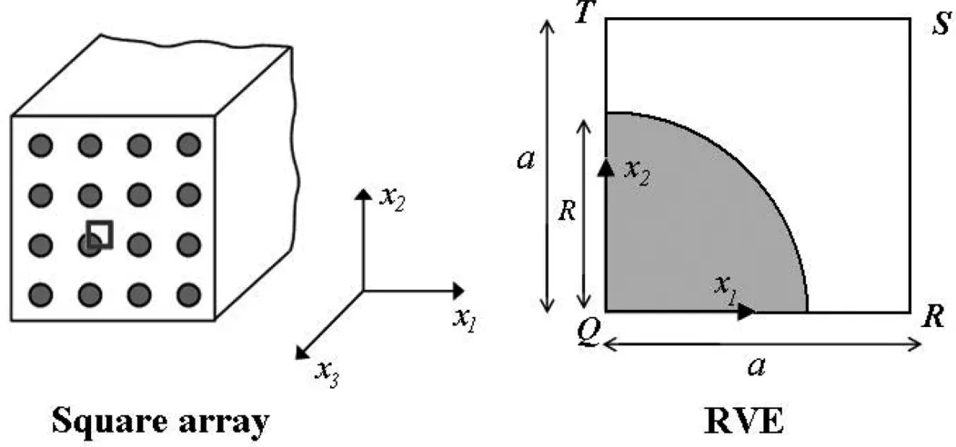
Figure 1:The cross section of the composite with square array,fiber distribution and corresponding RVE.

where u is the displacement vector and t is the traction vector on the interface and superscript f and m denote the fiber and matrix,respectively.
4.2 Loading conditions
In this study,it is assumed that the external stresses which are applied to the RVE are known and the displacement and stresses on the right ant top edge of the RVE is unknown.It is supposed that the average external normal stress(macro stress)which is applied to the composite in the xidirection is¯σi.So,the average stress on the right side,top side and over the area of the RVE is equal to the applied external stress as

These equations represent the external loading conditions which apply to the sides of the RVE and should be considered in the solution of the RVE.
5 Solution
5.1 Moving least square(MLS)approximation
One of the well-known methods used for approximation of the field variable u(x x x)over a number of randomly located nodes within the domain is the moving least squares(MLS)technique which is described in Atluri and Zhu(1998).In the MLS approximation,the nodal interpolation form of field variable u(x x x)may be expressed as

where φI(x x

5.2 Numerical discretization
In the case of the generalized plane strain condition in which the normal strain in the x3direction i.e.ε33= ε0is constant and ε13= ε23=0,the stress-strain form of the constitutive equations for fiber and matrix can be written using Eq.(10)to(15)as


In the generalized plane strain condition,the increment of the traction,i.e.dt on the boundary of the sub-domain in the matrix form can be obtained using Eq.(2)and Eq.(22)as

Substituting traction from Eq.(28)into Eq.(3)and using the MLS approximation lead to the discretized form of the governing equations as


It is seen that the domain integration is totally eliminated in this formulation.

5.3 Treatment of material discontinuity and boundary conditions
In the meshless methods there is no mesh of elements and the material interface cannot be defined based on the elements.In this paper,the selected RVE is considered as two homogeneous bodies.In order to treat the material discontinuity at the fiber-matrix interface,two sets of nodes are assigned to the fiber-matrix interface at the same location with different material properties.One set which is dedicated to the fiber known as Ifwhile the other set is related to the matrix denoted by Im.By this,the interface conditions in Eq.(20)for all of the nodes that are located at the interface in the same location can be written in the discretized form as

where Nfis the total number of nodes in the fiber and Nmis the total number of nodes in the matrix.Also according to Eq.(18)the essential boundary conditions on the bottom and left side of the RVE can be imposed in discrete form as

and the displacement conditions on the top and right sides of the RVE may be imposed as

where d¯ui,i=1,2 is the increment of the constrained displacement on the right and top side of the RVE,respectively.Equations(32)to(35)can be directly imposed to the global stiffness and the force matrix of the problem.For instance,in order to impose Eq.(34)to the node I that is located on the bottom edge and the left edge,the row of the global stiffness and force matrix in Eq.(31)which is related to the node I should be changed to

Furthermore,similar replacement in the global stiffness and the force matrix should be applied to all interface nodes based on the interface conditions in Eq.(32)and Eq.(33)and for all the constrained nodes based on Eq.(34)and Eq.(35).This leads to direct enforcement of the boundary and interface conditions to the system of equations.Finally,it is worth mentioning that the final stiffness matrix in this method is banded and asymmetric.
5.4 Implementation of the method(solution procedure)
In order to obtain the distribution of stress and displacement in the RVE,the differential equations of the problem must be integrated.In this study,a predictorcorrector method for numerical integration is used for solving the differential equations of the problem.The idea behind the predictor-corrector methods is using a suitable combination of an explicit and an implicit technique to obtain a method with better convergence characteristics.The procedure for solving the governing equations of the problem can be explained as below.For instance,suppose that an external load F is applied to the structure.
1-In the first step,a full elastic analysis is done and the load that causes the initial yield of the structure is predicted.This load is named FY.When FYis greater than the applied load F,i.e.FY>F,the structure is in the elastic region and the solution is finished.If F is greater than FY,i.e.F>FY,then the following procedure should be carried out.
2-The loading path is divided into a number of load increments ΔFi(i=1,2...N)and the first load increment ΔF1is taken equal to FY,i.e.ΔF1=FY.For the first load step an elastic analysis is done for obtaining displacements,stresses and effective stress,σe,at the end of the first load step ΔF1.
3-For the ithload increment(i>1),the plastic strain will be observed in some local domains inside the global domain,thus the elastic-plastic differential equations of the problem in Eq.(29)should be solved.As said before,for the gauss points that located in plastic regions the plastic index β=1 and therefore D=De+Dp.As mentioned before,a predictor-corrector method is employed for solving of the governing equations of the system.In the predictor-corrector method the results at the end of the ithload step are obtained from the results of(i-1)thload step in two stages.
5.4.1 Prediction stage
In the Prediction stage the results at the end of the ithload step are predicted from the results of the(i-1)thstep as follow

in which the superscript(p)denotes the predicted values.
5.4.2 Correction stage
In this stage,the results at the end of the ithload step are corrected using the results of the(i-1)thstep and the previous predicted values of the ithload step i.e.σ(p)which is obtained in Eq.(40)as follow

in which the superscript(c)denotes the corrected values.
4-The total displacement and the total stress at the end of the ithload step can now be obtained as

5-Steps 3 to 4 should be repeated until the applied load Fi=Fi-1+ΔFireaches the final level of the applied load F.The updated overall stress at each load level can be plotted against the overall strain in the same load level in order to obtain the stress-strain curve of the composite during the specified loading interval.
6 Numerical results and dissections


Table 1:The elastic properties of Boron fiber and Aluminum matrix in Boron/Aluminum composite system[Adams and Crane(1984)].
6.1 Convergence study and CPU time

Figure 2:Convergence study of the meshless and finite element method with respect to number of nodes,(σ∗1=180 MPa).
The rate of convergence and the CPU time of the presented method are studied in this section.Fig.2 shows the transverse displacement(u1)on the right hand side(x1=a)of the RVE for transverse loading asσ1=180MPa for various numbers of nodes in the RVE.It must be noticed that theu1displacement is the same for all the nodes on the right side of the RVE.To comparison,another analysis was also carried out using the commercial finite element code ANSYS by 4 node plane elements.Details of the modeling and imposing boundary conditions can be found in Aghdam,Smith,and Pavier(2000).The prediction of the analysis with ANSYS is also included in Fig.2.It is seen that very good convergence can be achieved by using about 500 nodes in the meshless method while FE analysis requires more than 1000 nodes for the same level of convergence.Therefore,in all presented results in this section 500 or some more nodes are used for meshless and 1180 nodes(1092 elements)are used for FE analyses,respectively.
Moreover,the efficiency of the presented method is examined with respect to the MLPG method which first was introduced by Atluri and Zhu(2000).This MLPG method[Atluri and Zhu(2000)]uses symmetric weak formulation and domain integration in the local sub-domains and is so-called MLPG1 method[Atluri and Shen(2002)].In order to examine the efficiency of the presented method with respect to the MLPG1,a same code is developed for analysis of the problem based on the conventional MLPG formulation.The node distribution,MLS approximation and size of sub-domains are chosen exactly the same in both codes.Table 2 compares the CPU time of the presented meshless formulation with the MLPG1 formulation and ANSYS.It should be noted that in the presented method,the domain integration over the sub-domains is eliminated and therefore,all numerical integrations were carried out only over the boundary of the sub-domains.Therefore,for the presented meshless method,the Gauss points in the radial direction i.e.nrare eliminated and only the number of Gauss points in the circumferential direction,i.e.nθis reported in Table 2.As said before,circular sub-domain around the nodes is used in this study and the Gauss points are located on the boundary of the circles.It can be seen that elimination of the domain integration in the presented method yields to substantial reduction of the computational time.In all of the presented results 10 Gauss points are used for numerical integration on the boundary of thesub-domains.The prediction of the finite element for effective transverse modulus is also included in Table 2.The prediction of present model for effective elastic modulus of the composite is between the predictions of the MLPG and ANSYS.The node distribution(computational model)which is used in the analysis of the RVE is shown in Fig.3.In the analysis of the problem,a fourth-order spline-type function is used as the weight function in construction of the shape function via the MLS method.According to the node distribution in Fig.3,the radius of support domain in construction of the shape function for nodes depend on the density of nodes located around that node.The radius of support domain is selected large enough so that at least a node in radial direction and a node in circumferential direction in the neighborhood of the node are located inside the support domain of that node or at least 4 neighborhood nodes locate in it.In general rsupp=adminand rtest=bdminin which dminis the distance between the node and nearest neighborhood node.a and b are chosen by the user.The choice of a is governed by the nodal arrangement,the dimension of the problem and the order of the monomial basis,whereas the choice of b depends only on the nodal arrangement.The test radius must be large enough so that the domain completely is covered.In this study a and b is chosen depends on the nodal distribution between 1.8 to 2.5.a usually is chosen about 2.5 and b is chosen about 1.8.

Table 2:Compression of the CPU time of the current meshless method and the MLPG1 method.
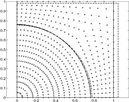
Figure 3:The nodal distribution form which is used in the meshless method,undeformed(solid line),deformed scaled by 30(dashed line).
Fig.3 shows the un-deformed and also the deformed shape of the RVE which is subjected to σ∗1=180MPa.The deformation of the RVE is exaggerated by a scale factor as 30.
6.2 Stress-strain response of B/Al composite
The stress-strain response of the B/Al composite in transverse loading is investigated in this section.The predicted elastic properties of the B/Al composite with 45.5%FVF are shown in Table 3.Also this table contains the predicted yield strength of the B/Al composite in the axial and transverse direction.As seen in Table 3,the predicted values of the present method are in excellent agreement with the predictions of the finite element analysis with ANSYS.

Table 3:The predicted elastic properties of Boron/Aluminum composite with 45.5%FVF.
The predicted elastic-plastic stress-strain response diagram of the B/Al composite with 45.5%fiber volume fraction in transverse loading is shown in Fig.4.In this Figure,the overall stress level in each load step is plotted vs.the overall strain in the same step.The predictions of the presented meshless method and the finite element analysis with ANSYS are included in this Figure.As seen in Fig.4,the predictions of the meshless and finite element method are in excellent agreement.The initial local yield stress of the composite in the transverse loading is predicted asσY1=125.486MPa.It is seen that the presented meshless model shows excellent agreement with the finite element method in the prediction of the overall properties of the B/Al composite.

Figure 4:Stress-strain curve of B/Al metal matrix composite in transverse loading(45.5%FVF).
6.3 Displacement and micro-stresses
The distributions of the local field variables in the RVE subjected to transverse normal load are studied in this section.The distribution of displacement in the x1direction,u1,on the bottom path(x2=0,0<x1<a)and on the top path(x2=a,0<x1<a)of the RVE for transverse applied load σ1∗=180 MPa are shown in Fig.5.As expected,the distribution of the displacement is continuous in the fiber-matrix interface.Excellent agreement is seen between the meshless and the finite element method in the prediction of the displacement field in the RVE.The distribution of the micro-stresses,σ1,σ2,σ3and σeffon the bottom path of the RVE is shown in Fig.6.As seen,the transverse stress σ1is continuous at the fibermatrix interface.The axial stress σ3is compressive in the fiber and is tensile in the matrix and is discontinuous at the fiber-matrix interface.The transverse stress σ2is discontinuous at the interface.The distribution of the effective Von Misses stress σeffis shown in this Figure.On the bottom path,the matrix has been entered into the plastic region.As seen in Fig.6,because the hardening modulus of the matrix in the plastic region is very small(ET=1.17 GPa),the distribution of σeffstress in the matrix on the bottom path is almost uniform.The distribution of the micro-stresses σ1,σ2,σ3and σeffon the left path(x1=0)of the RVE for applied stress σ∗1=180 MPa is shown in Fig.7.This load causes the plastic deformation in the matrix.As seen,on the left path,σ2stress is compressive and continuous at the fiber-matrix interface while theσ1,σ2andσeffare discontinuous at the interface.σ1andσeffin the fiber is larger than in the matrix.
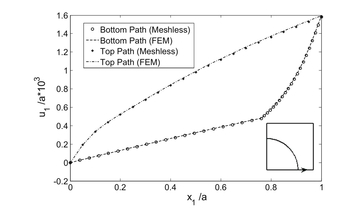
Figure 5:Distribution of displacement on the bottom and top path of the RVE(σ∗1=180MPa).

Figure 6:Distribution of micro-stresses σ1,σ2,σ3and σeffon the bottom path of the RVE,(σ∗1=180MPa).
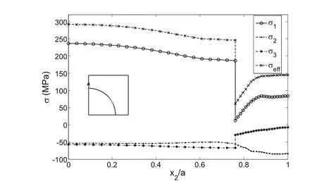
Figure 7:Distribution of micro-stresses σ1,σ2,σ3and σeffon the left path of the RVE,(σ∗1=180MPa).
6.4 Micro-strains
The distribution of the micro-plastic strains on the bottom path of the RVE forσ∗1=180 MPa is shown in Fig.8.As seen in Fig.8,theεp1is positive andεp2andεp3are negative on the bottom path.The equivalent plastic strainεpequ≈εpis also shown in this Figure.The maximum ofεp1which is occurred on the bottom path at point(a,0)is about 0.5%.In Fig.8,forx1/a>0.76 plastic strains are observed in the matrix and forx1/a<0.76 the plastic strains are vanished.The distribution of micro-plastic strains on the left path of the RVE forσ∗1=180MPa is shown in Fig.9.As seen,forx2/a<0.89 the plastic strains are vanished.εp1is positive andεp2andεp3is negative on this path.
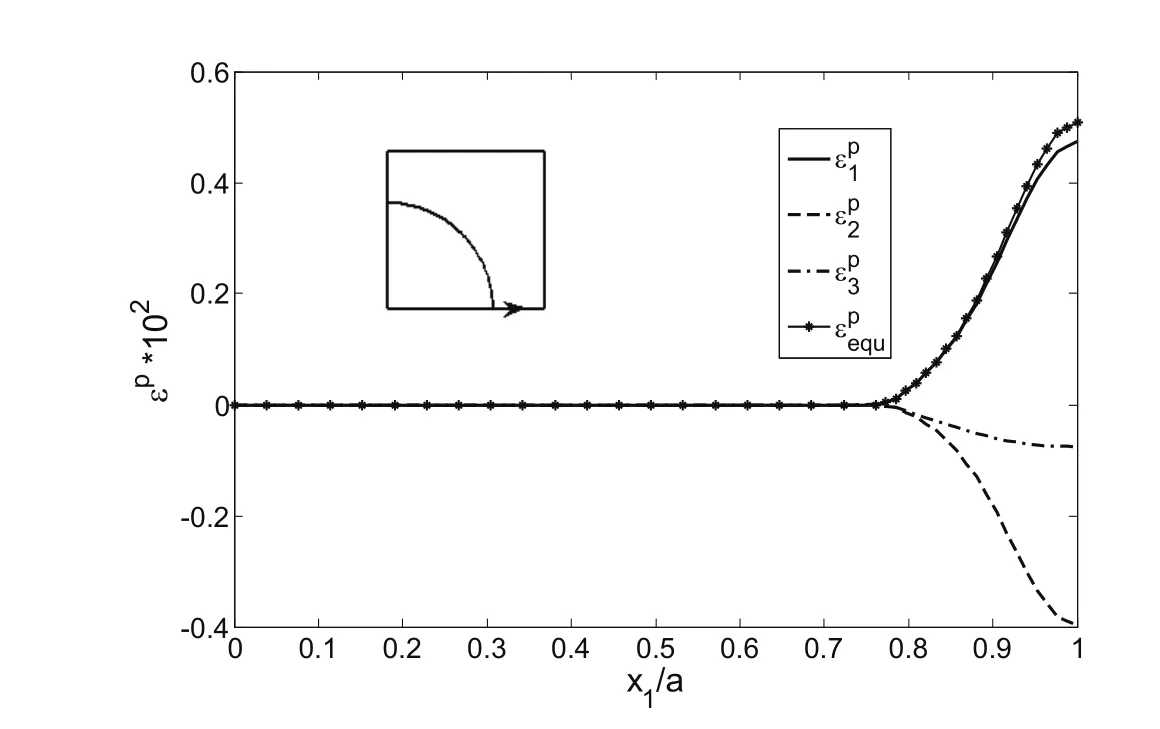
Figure 8:Distribution of micro-plastic strains ε1p,ε2pand εepquon the bottom path of the RVE,(σ1∗=180MPa).
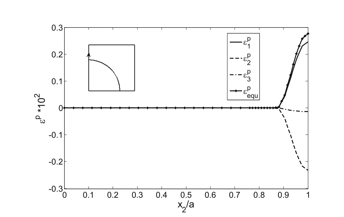
Figure 9:Distribution of micro-plastic strains ε1p,ε2p,ε3pand εepquon the left path of the RVE,(σ1∗=180MPa).
6.5 Elastic-plastic load reversal
In this section it is supposed that the RVE is loaded in the transverse direction to the macro-stress as σ∗1=180 MPa and then unloaded to 0 and reloaded to compressive transverse normal stress as σ∗1=-180 MPa.The Prager’s linear kinematic hardening model is employed for the Aluminum.The distribution of the normal stresses on the bottom path of the RVE is shown in Fig.10.This figure includes the normal stresses σ1,σ2,σ3and effective von misses stress σeffwhen the RVE is loaded in transverse x1direction from 0 to 180 MPa and the loaded to-180 Mpa.The σ1stress is compressive through the path and σ2is so that it integration on the path is vanished.
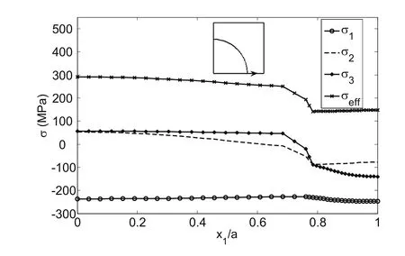
Figure 10:Distribution of micro-stresses σ1,σ2,σ3and σeffon the bottom path of the RVE,(loading to σ∗1=180MPa and reloading to σ∗1=-180MPa).
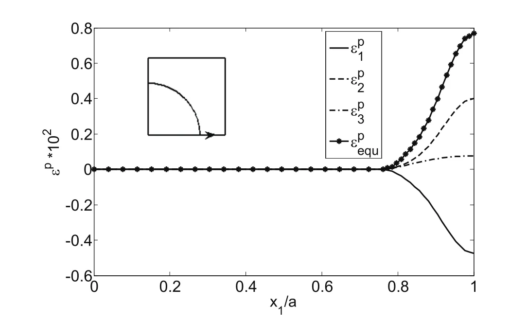
Figure 11:Distribution of micro-plastic strains ε1p,ε2pand εepquon the bottom path of the RVE,(loading to σ1∗=180MPa and reloading to σ1∗=-180MPa).

7 Conclusions
In this study a meshless method based on the meshless local Petrov-Galerkin method is presented for the elastic-plastic analysis of solid structures.Because the domain integration is eliminated from the formulation,the computational cost is reduced.The well-known Prandtl-Reuss flow rule and the incremental theory of plasticity are used for the formulation of the nonlinearity of the problem due to the plastic strains.The presented method is formulated for the generalized plane strain case.The presented meshless method is conjugated with a generalized plane strain micromechanical model for the analysis of the elastic-plastic behavior of the unidirectional composite materials.The fully bonded interface is considered and a direct method is developed to enforce the continuity of displacement and traction at the fibermatrix interface.The Euler integration method is employed for the integration of the discrete governing differential equations of the system.The Boron/Aluminum metal matrix composite subjected to transverse loading condition is studied.The predicted results for the overall and local response of Boron/Aluminum show good agreement with the predictions of the finite element method.
Appendix
To determine the unknown parameter dλ in the Prandtl-Reuss flow rule,Eq.(6)is multiplied by itself and is written as

The effective stress σe,and the effective plastic strain increment dεpare defined as

Now,by employing(A2)in(A1),the parameter dλ and the plastic strain increment can be obtained in terms of dεpand σeas


In order to establish a relationship between the effective stress σeand the effective plastic strain increment dεp,the uniaxial tensile test in the plastic region is considered.In the uniaxial tensile test,σeand dεpwill be obtained as

and the plastic strain increment in the uniaxial loading can be obtained as

In which ET=dσ/dε is the hardening modulus of the material in the plastic region and E is the elastic module of the material.By substituting Eq.(A5)in Eq.(A6)it can be concluded that

By substituting Eq.(A7)into Eq.(A3),the parameter dλ can be obtained as

By differentiating Eq.(A2),dσemay be obtained.

and substitution of Eq.(A10)into Eq.(A9)yields

In the theory of plasticity,it is usually assumed that no plastic work can be done by the hydrostatic component of stress,i.e.

So,dλcan be obtained by the substituting Eq.(A12)into Eq.(A11)as

The total strain increment dεijcan be calculated by substituting Eq.(6)in the strainstress relation in Eq.(4)as

The sides of this equation are multiplied bySijas

The first term in the right side of Eq.(A15)can be rewritten using Eq.(A13)as

and the second term in the right side of Eq.(A15)can be written as

By employing Eq.(A16),(A17)and(A2),Eq.(A15)can be rewritten as

Now,dλcan be obtained in terms of dεijas

Aboudi,J.(1996):Micromechanical analysis of composites by the method of cells-Update.Appl.Mech.Rev.,vol.49,no.10,pp.S83-S91.
Adams,D.F.(1970):Inelastic analysis of unidirectional composite subjected to transverse normal loading.J.Comp.Mater.,vol.4,pp.310-328.
Adams,D.F.;Crane,D.A.(1984):Combined loading micromechanical analysis of a unidirectional composite.Composites,vol.15,no.3,pp.181-192.
Aghdam,M.M.;Smith,D.J.;Pavier,M.J.(2000):Finite element micromechanical modelling of yield and collapse behaviour of metal matrix Composites.J.Mech.Phys.Solids,vol.48,pp.499-528.
Ahmadi,Isa;Aghdam,M.M.(2010):A generalized plane strain meshless local Petrov-Galerkin method for the micromechanics of thermo-mechanical loading of composites,Journal of Mechanics of Materials and Structures,vol.5,no.4,pp.549-566.
Ahmadi,Isa;Aghdam,M.M.(2011a):Heat transfer in composite materials using a new truly local meshless method.International Journal of Numerical Methods for Heat&Fluid Flow,vol.21,no.3,pp.293-309.
Ahmadi,Isa;Aghdam,M.M.(2011b):A truly generalized plane strain meshless method for combined normal and shear loading of fibrous composites.Engineering Analysis with Boundary Elements,vol.35,pp.395-403.
Arnoled,S.M.;Pindera,M.J.;Wilt,T.E.(1996):Influence of fiber architecture on the inelastic response of metal matrix composites.Int.J.of Plasticity,vol.12,pp.507-545.
Atluri,S.N.;Shen,S.(2002):The meshless local Petrov-Galerkin(MLPG)method:a simple&less-costly alternative to the finite element and boundary element methods.CMES:Computer Modeling in Engineering&Sciences,vol.3,no.1,pp.11-51.
Atluri,S.N.(2004):The meshless method(MLPG)for domain and BIE discretizations,Tech Science Press,Forsyth.
Atluri,S.N.;Zhu,T.(1998):A new meshless local Petrov-Galerkin(MLPG)approach in computational mechanics.Comput.Mech.,vol.22,pp.117-127.
Atluri,S.N.;Zhu,T.(2000):The meshless local Petrov-Galerkin(MLPG)approach for solving problems in elastostatics.Comput.Mech.,vol.25,pp.169-179.
Batra,R.C.;Porfiri,M.(2008):Analysis of rubber-like materials using meshless local Petrov-Galerkin(MLPG)method.Commun.Numer.Meth.En.,vol.24,no.12,Sp.Iss.SI,pp.1781-1804.
Belinha,J.;Dinis,L.M.J.S.(2006):Analysis of plates and laminates using the element-free Galerkin method.Comput.Struct.,vol.84,pp.1547-1559.
Belytschco,T.;Lu,Y.Y.;Gu,L.(1995):Crack propagation by element free galerkin methods.Eng.Frac.Mech.,vol.51,no.2,pp.211-222.
Belytschko,T.;Lu,Y.Y.;Gu,L.(1994):Element-free Galerkin methods.Int.J.Numer.Methods Engrg.,vol.37,pp.229-256.
Ching,H.K.;Batra,R.C.(2001):Determination of crack tip fields in linear elastostatics by the meshless local Petrov-Galerkin(MLPG)method.CMES:Computer Modeling in Engineering&Sciences,vol.2,no.2,273-290.
Coker,D.;Ashbaugh,N.E.;Nicholas,T.(1993):Analysis of thermomechanical cyclic behavior of unidirectional metal matrix composites.Thermomechanical fatigue Behavior of Materials,ASTM STPvol.1186,Sehitoglu ed.pp.50-69.
Dai,K.Y.;Liu,G.R.;Han,X.;Li,Y.(2006):Inelastic analysis of 2D solids using a weak-form RPIM based on deformation theory.Comput.Methods Appl.Mech.Engrg.,vol.195,pp.4179-4193.
Ding,S.R.;Tong,J.W.;Shen,M.(2005):Numerical simulation of elastic-plastic behavior of thermoplastic composites.J.Reinf.Plast.Comp.,vol.24,pp.649-655.
Dong,L.;Alotaibi,A.;Mohiuddine,S.A.;Atluri,S.N.(2014):Computational methods in engineering:a variety of primal&mixed methods,with global&local interpolations,for well-posed or Ill-Posed BCs,CMES:Computer Modeling in Engineering&Sciences,vol.99,no.1,pp.1-85.
Duarte,C.A.M.;Oden,J.T.(1996):An h-p adaptive method using clouds.Comput.Methods Appl.Mech.Engrg.,vol.139,pp.237-262.
Dvorak,G.J.;Bahei-El-Din,Y.A.(1979):Elastic-Plastic behaviour of fibrous composite.J.Mech.Phys.Solids,vol.27,pp.51-72.
Dvorak,G.J.;Bahei-El-Din,Y.A.(1982):Plasticity Analysis of fibrous composite.ASME J.Appl.Mech.,vol.49,pp.327-335.
Foye,R.L.(1973):Theoretical post-yeilding of behaviour of composite laminates,Part I-Inelastic micromechanics.J.Comp.Mater.,vol.7,pp.178-193.
Gu,Y.T.;Liu,G.R.(2001):A meshless local Petrov-Galerkin(MLPG)formulation for static and free vibration analysis of thin plates.CMES:Computer Modeling in Engineering&Sciences,vol.2,no.4,pp.463-476.
Gu,Y.T.;Liu,G.R.(2002):A boundary point interpolation method for stress analysis of solids.Comput.Mech.,vol.28,47-54.
Gu,Y.T.;Wang,Q.X.;Lam,K.Y.;Dai,K.Y.(2007):A pseudo-elastic local meshless method for analysis of material nonlinear problems in solids.Eng.Anal.Bound.Elem.,vol.31,pp.771-782.
Han,Z.D.;Rajendran,A.M.;Atluri,S.N.(2005):Meshless local Petrov-Galerkin(MLPG)approaches for solving nonlinear problems with large deformations and rotations,CMES:Computer Modeling in Engineering&Sciences,vol.10,no.1,pp.1-12.
Heaney,C.;Augarde,Ch.;Deeks,A.(2010):Modelling Elasto-Plasticity Using the Hybrid MLPG Method.CMES:Computer Modeling in Engineering&Sciences,vol.56,no.2,pp.153-177.
Hill,R.(1964):Theory of mechanical properties of fiber-strengthened materials.II.Inelastic Behaviour.J.Mech.Phys.Solids,vol.12,pp.213-218.
Hill,R.(1965):Theory of mechanical properties of fiber-strengthened materials.III.Self-Consistent Model,J.Mech.Phys.Solids,vol.13,pp.189-198.
Huang,Z.M.(2000):A unified micromechanical model for the mechanical properties of two constituent composite materials Part II:Plastic behavior.J.Thermoplastic Comp.Mater.,vol.13,pp.344-362.
Hung,W.(1973):Elastoplastic transverse properties a unidirectional fiber reinforced composites.J.Comp.Mater.,vol.7,pp.482-499.
Li,G.;Belytschko,T.(2001):Element-free Galerkin method for contact problems in metal forming analysis.Eng.Comput.,vol.18,pp.62-78.
Lin,H.;Atluri,S.N.(2001):The meshless local Petrov-Galerkin(MLPG)method for solving incompressible Navier-Stokes equations.CMES:Computer Modeling in Engineering&Sciences,vol.2,pp.117-142.
Lin,T.H.;Salinas,D.;Ito,Y.M.(1972):Initial yeild surface of a unidirectionally reinforced composite.ASME J.Appl.Mech.,vol.39,pp.321-329.
Liu,W.K.;Chen,Y.;Chang,C.T.;Belytschko,T.(1996):Advances in multiple scale kernel particle methods.Comput.Mech.,vol.18,pp.73-111.
Long,S.Y.;Liu,K.Y.;Hu,D.A.(2006):A new meshless method based on MLPG for elastic dynamic problems.Eng.Anal.Bound.Elem.,vol.30,43-48.
Mendelson,A.(1970):Plasticity:Theory and Application.MacMillan,New York.
Mukherjee,Y.X.;Mukherjee,S.(1997):Boundary node method for potential problems.Int.J.Numer.Methods Engrg.,vol.40,pp.797-815.
Nayroles,B.;Touzot,B.;Villon,P.(1992):Generalizing the finite element method:diffuse approximation and diffuse elements.Comput.Mech.,vol.10,pp.307-318.
Perez Pozo,L.;Perazzo,F.;Angulo,A.(2009):A meshless FPM model for solving nonlinear material problems with proportional loading based on deformation theory.Adv.Eng.Software,vol.40,pp.1148-1154.
Robertson,D.D.;Mall,S.(1993):Micromechanical relation for fiber reinforced composites using a free transverse shear approach.J.Comp.Tech.and Res.,vol.15,pp.181-192.
Singh,I.V.;Sandeep,K.;Prakash,R.(2002):The element free Galerkin method in three-dimensional steady state heat conduction.Int.J.Comput.Eng.Sci.,vol.3,pp.291-303.
Sladek,J.;Sladek,V.;Tan,C.L.;Atluri,S.N.(2008):Analysis of transient heat conduction in 3D anisotropic functionally graded solids by the MLPG,CMES:Computer Modeling in Engineering&Sciences,vol.32,pp.161-174.
Sladek,J.;Sladek,V.;Atluri,S.N.(2004):Meshless local Petrov-Galerkin method for heat conduction problem in an anisotropic medium.CMES:Computer Modeling in Engineering&Sciences,vol.6,no.3,pp.309-318.
Sladek,J.;Sladek,V.;Solek,P.(2009):Elastic analysis in 3D anisotropic functionally graded solids by the MLPG,CMES:Computer Modeling in Engineering&Sciences,vol.43,no.3,pp.223-251.
Sladek,J.;Stanak,P.;Han,Z-D.;Sladek,V,;Atluri,S.N.(2013):Applications of the MLPG method in engineering&sciences:A review,CMES:Computer Modeling in Engineering&Sciences,vol.92,no.5,pp.423-475.
Sukumar,N.;Moran,B.;Belytschko,T.(1998):The natural element method.Int.J.Numer.Methods Engrg.,vol.43,pp.829-887.
Sun,C.T.;Chen,J.L.(1991):A Micromechanical Model for Plastic Behavior of Fibrous Composites.Comp.Sci.Tech.,vol.40,pp.115-129.
Taliercio,A.(2005):Generalized plane strain finite element model for the analysis of elastoplastic composites.Int.J.Solids Struct.,vol.42,pp.2361-2379.
Zhu,C.;Sun,C.T.(2003):Micromechanical Modeling of Fiber Composites Under Off-Axis Loading.J.Thermoplastic Comp.Mater.,vol.16,pp.333-344.
Zhu,T.;Zhang,J.-D.;Atluri,S.N.(1998):A local boundary integral equation(LBIE)method in computational mechanics,and a meshless discretization approach.Comput.Mech.,vol.21,pp.223-235.
1Corresponding author,Advanced Materials and Computational Mechanics Lab.,Department of Mechanical Engineering,University of Zanjan,45371-38791,Zanjan,Iran,E-mail:i_ahmadi@znu.ac.ir,Tell:+98 24 3305 4058
2Department of Mechanical Engineering,Amirkabir University of Technology,Tehran,Iran

