Research for load sensing technology of shotcrete mechanical arm based on AMESim
Shou-lei JIANG, Shou-bo JIANG, Guo-guan MA
(Shandong University of Science & Technology, Qingdao 266590, China)
Research for load sensing technology of shotcrete mechanical arm based on AMESim
Shou-lei JIANG*, Shou-bo JIANG, Guo-guan MA
(Shandong University of Science & Technology, Qingdao 266590, China)
The working principle of shotcrete mechanical arm was reviewed, and the structure and working principle of load sensing technology was described in this paper. Based on an AMESim model for load-sensing system, the characteristics of pressure and flow for Load-sensing-system was analyzed to understand the benefits of load sensing system and theoretical basis for design and development of shotcrete mechanical arm.
Shotcrete mechanical arm, Load sensing system, AMESim, Pressure characteristics, Flow characteristics
1 Introduction
The means of shotcrete shoring were mostly used during the process of roadway excavation. Shotcrete was completed in the way of holding airbrush by workers in the past. This approach could not only result in heavy labor tasks and influence the health of workers, but also become difficult to ensure the quality. Shotcrete mechanical arm was developed rapidly from the late 1960s so that labor tasks of workers was reduced greatly. The drive mode of shotcrete mechanical arm is full hydraulic drive. However, there is an unavoidable problem for hydraulic drive which has poor efficiency. Now we can solve this problem with the development of load sensing technology.
2 The working principle of shotcrete mechanical arm
The small mine-used shotcrete mechanical arm has five degrees of freedom which are pitching, swing, telescopic of arm, swinging back and forth, swinging left and right of sprinklers in order to meet the construction requirements in the spraying process. Walking track was mounted on the shotcrete mechanical arm to easily move in the process of working. The overall organization chart of small mine-used shotcrete mechanical arm is shown in Fig.1. Hydraulic schematics of shotcrete mechanical arm are shown in Fig. 2.
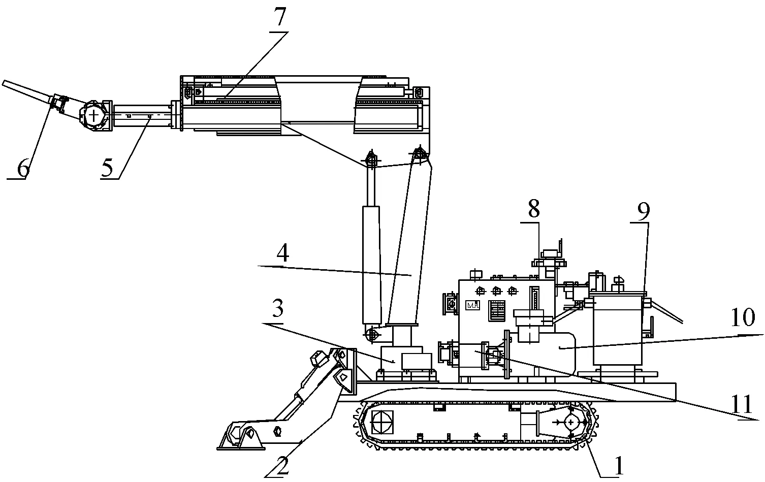
1.walking track; 2.support legs; 3.rotary support; 4.support arm; 5.spiral swing cylinder; 6.sprinkler; 7.arm; 8.valve; 9.launcher; 10.motor; 11.pump
Fig.1 The overall organization chart of small mine-used shotcrete mechanical arm
3 The working principle of load sensing system
Load sensing system is a kind of closed-loop system with pressure feedback. It could achieve servo control of load pressure by pump in the case of satisfying the flow requirements. Also it could realize adaptive between pump and execution unit by automatically adjusting the pump flow according to the load pressure. In this way, pump will provide oil as required so that it can reduce flow loss. Moreover, each actuator of load sensing system is non-interference which ensure that the system has a good independence. Now, load sensing system has widely used in engineering machinery.

Fig.2 Hydraulic schematics of shotcrete mechani-cal arm
Fig.3 shows the working principle of load sensing system [1]. Control section is composed by variable pump, reset cylinders, variable hydraulic cylinders, throttle, load sensing valve and pressure shut-off valve. Hydraulic oil from variable pump in the system produces a certain pressure drop with the function of throttle so that there will generate a pressure difference at both ends of load sensing valve. Furthermore, deviation force caused by pressure difference is equal to spring preload. One could obtain the relationship of flow and pressure drop by Bernoulli equation [2]:
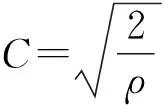
Where,Qstands for the flow through the throttle valve, m3/s;Astands for the opening area of the orifice of throttle, m2; Δpstands for the pressure difference of throttle, Pa;Cstands for a flow coefficient;ρstands for density of hydraulic oil, kg/m3.
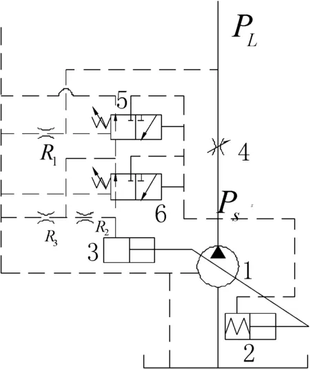
1.variable pump; 2.reset cylinders; 3.variable hydraulic cylinders; 4.throttle; 5.load sensing valve; 6.pressure shut-off valve
Fig.3 Working principle of load sensing system
When throttle is closed, load will stop working and the system will be in standby mode. Hydraulic oil gets into variable hydraulic cylinders through load sensing valve so that the flow of pump will reach to the minimum value. The output pressure of pump is just set pressure of load sensing valve which is usually around 1.4 MPa. In this case, system unloads without flow rate and power consumption also closes to zero.
When the system is overloaded, it cannot make actuators work. When the system is in the state of maintaining the pressure, there is no need to make actuators work. In this case, the output pressure of pump will continue to rise due to the pressure on the left end of load sensing valve until the output pressure becomes greater than the set pressure of constant pressure valve. This output pressure will make constant pressure valve work. Hydraulic oil gets into variable hydraulic cylinders so that the flow of pump will reduce to maintain the control of system and reduce the leakage. In this way, swash plate of variable pump is close to zero, also power reaches the minimum.
When the system is in adaptive state, the load of system will be increased due to the increase of throttle opening. Load sensing valve will be on the left end because of decreasing of pressure difference of throttle(Δp=PS-PL) so that there will be a torque difference of swash plate caused by pushing of pump. This torque difference will increase swash plate, also increase the output flow of pump until it meets the required flow of load. When throttle opening is decreased, the system will produce the opposite effect.
4 Modeling and simulation of load sensitive systems
In order to analyze the hydraulic circuit and working principle of load sensing system for mine-used shotcrete mechanical arm, an AMESim model of load sensing system of shotcrete mechanical arm was established, as shown in Fig.4 [3]. The parameters were set as follows: the motor speed is 1 500 r/min, the output of variable pump is 13 mL/r. The actuator includes only one hydraulic cylinder, diameter of piston of cavity without arm is 80 mm, diameter of piston of cavity with arm is 40 mm,the setting pressure of proportional relief valve is 16 MPa, the setting pressure of load sensing valve is 1.4 MPa, the bulk modulus of hydraulic oil is 1700 MPa, the density of hydraulic oil is 850 kg/m3, the absolute viscosity is 51cp and the temperature is 40 ℃ [4].
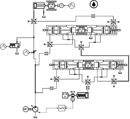
Fig.4 The model of load sensitive system
Fig.5 shows the curve of output pressure of load sensing system. Fig.6 shows the curve of flow characteristics of load sensing system. If the working pressure of system is 16 MPa and the pressure difference on both ends of load sensing valve is always keep in 1.4 MPa, when the working pressure of system does not reach to the maximal value, there is a linear relationship between the flow and opening area of throttle because the pressure difference of throttle is remained the same. When the load pressure reaches or exceeds the setting maximum working pressure of system, the outlet pressure of pump will be remained at 16 MPa and the flow of pump will be gradually reduced to zero. So we can conclude that the speed adjustment range of load sensitive system is relatively wide, also the load sensitive system can realize the stepless speed regulation. Although the system has a smaller throttle loss, the system does not have overflow loss. When the outlet pressure of pump is greater than load pressure by 1.4 MPa, the pressure of system loss becomes smaller [5].

Fig.5 Curve of output pressure of load sensing system
As shown in Fig.6 and Fig.7, when the system load continuously changes from 0 MPa to 16 MPa, the pressure difference of throttle will be greater than 1.4 MPa and the flow of variable pump will be kept at 19.5 L/min due to the working of load sensing valve. Now we can conclude that the flow of pump is only related with the opening area of throttle valve, and it has nothing to do with load. Therefore, that the load sensing system has a good load adaptability.
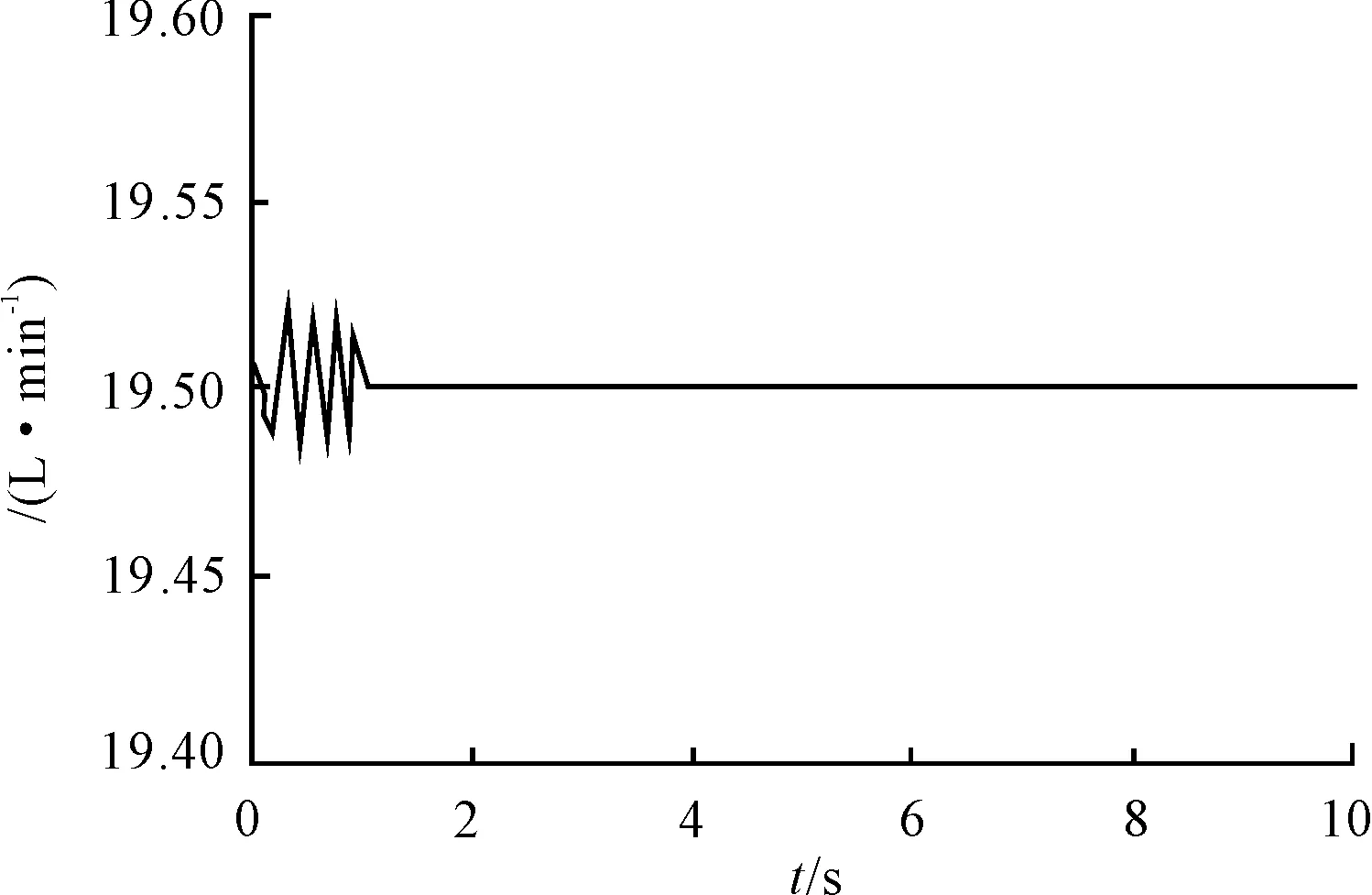
Fig.6 Curve of flow characteristics of load sensing system

Fig.7 Curve of adaptation characteristics of load sensing system
5 Conclusions
Load sensing system can be applied at shotcrete mechanical arm due to some advantages such as good adaptability, overload protection and mutual non-interference between the actuators. Here we explained the need for the development of load sensing technology by building and analyzing the model of load sensing system. With the development of load sensing technology, its application will become more extensive.
Acknowledgements
This paper is supported by Innovation Fund of Shandong University of Science and Technology (No. YC140314) and Innovation Fund of Shandong University of Science and Technology (No. YC150105).
[1]Wang Guanglei,Tong Zhixue,Zhang Zhanping. Simulation study on load sensing system of hydraulic manipulators based on AMESim [J]. Mining & Processing Equipment, 2011(12): 106-109.
[2]Li Zhipeng,Liu Yang,Zhang Jianqi. Simulation on the load sensitive system of tree transplanting machines based on AMESim [J]. Forest Engineering, 2014(3): 104-107.
[3]Wu Xiaoguang,Song Haitao,Yin Xinsheng. Simulation analysis of drilling load sensing system based on AMESim [J]. Hydromechatronics Engineering, 2008(3):163-164, 195.
[4]Wang Longpeng. Research on load-sensing pump-control rotating system of drilling rig based on AMESim [J]. Coal Mine Machinery, 2014(6): 66-68.
[5]Wu Zhengming, Shi Qinglu, Bai Pengwei. Simulation analysis of load sensing system based on AMESim [J].Construction Machinery and Equipment, 2013(1): 38-41.
基于AMESim的喷浆机械手负载敏感技术的研究
江守雷*,江守波,马官国
山东科技大学,山东 青岛266590
综述了喷浆机械手的工作原理,阐述了负载敏感技术的构成和工作原理,建立了负载敏感系统的AMESim模型,通过对系统的仿真研究,分析了负载敏感系统的压力及流量特性,为了解负载敏感系统的优点提供了数据支持,并为喷浆机械手的设计及发展提供了理论依据。
喷浆机械手; 负载敏感系统;AMESim; 压力特性; 流量特性
4 Feburary 2015; revised 16 Apirl 2015;
Shou-lei JIANG,
E-mail:727576376@qq.com
10.3969/j.issn.1001-3881.2015.18.016 Document code: A
TH137
accepted 11 June 2015
Hydromechatronics Engineering
http://jdy.qks.cqut.edu.cn
E-mail: jdygcyw@126.com
- 机床与液压的其它文章
- Design and simulation of the hardware in the loop simulation platform for vehicle ACC system
- A research on film thickness of a typical dynamic seal for hydraulic actuators
- The research on aero-engine gas path fault diagnosis by genetic algorithm-BP neural network
- The design of the hydraulic cylinder test bed based on cartridge valves
- Numerical simulation on the aerodynamic performance of ice coating airfoil of wind turbine blade
- Manufacturing of self-lubricating diamond tools with Ni-Cr alloy adding with Ni/C

