Applicability of Two Kinds of Micromixers for High Viscosity Fluid Emulsification Process
WANG Kai, LIU Da-bin, QIAN Hua, XU Sen, LI Chang-hong, LI Xue-fei
(1. School of Chemical Engineering, Nanjing University of Science and Technology, Nanjing 210094, China; 2. MicroChem (Dalian) Co, Ltd, Dalian 116000, China)
1 Introduction
Emulsion explosive is widely used in the industry, which is manufactured by sensitization of emulsion matrix. Emulsion matrix of emulsion explosives is generally a high volume ratio of to outer phase, which is a water-in-oil emulsion containing droplets of oxidizer solution. Emulsification process is a key to the preparation of emulsion explosive. The traditional emulsification equipments include colloid mill, emulsifying tank, continuous emulsifier, etc. Their emulsification principle is the relative motion of the stator and rotor, which will easily cause accidental detonation of emulsion matrix. In this process, the stirring action of the rotor will increases the temperature of emulsion matrix, and when unexpected collision occurs, the matrix will be fired or explode due to the spark. And the emulsifying cavity of traditional emulsification equipment is big to keep a great quantity of explosives, which would be a security hidden danger[1].
Micromixers are mixers of micron scale, increasing the surface area of the fluid greatly and performing efficient emulsification[2-12]. Micromixer has simple structure without amplification effect, and the operating conditions are easy to be controlled. Currently micromixer has been widely used in the field of chemistry and biotechnology[13-14]. Since the amount of explosives deposited in the microchannel of micromixer is small, the possibility of accidental detonation decreases to very low level. Besides there is no moving part in the microchannel, which will greatly improve the security of emulsification process.
The water and oil phase are transported into the micromixer by two pumps. Through the role of energy conversion of micromixers, the mechanical energy of the fluid produced by the two pumps is converted into the interfacial energy of emulsion matrix[15]. As is well known, emulsion matrix is colloid with high viscosity, while the initial raw materials such as the oxidant solution and the oil phase solution are lower viscosity fluid. From the first emulsion to the second emulsion, following the emulsification process, the fluid viscosity increases.
No single micromixer is believed to be suitable for both low viscosity liquid and high viscosity fluid. Therefore, the emulsifications of emulsion matrix are divided into two stages, the first emulsion and the second emulsion[16]. To complete the first emulsion, a passive micromixer was made by filling the stainless steel tube with spiral metal mesh. In this study, the proposed micromixer was named as a metal mesh embedded micromixer (MMEM). The second emulsion was completed by the caterpillar split-recombine micromixer (CPMM) from Institut für Mikrotechnik Mainz GmbH(IMM). In this study, the MMEM and the CPMM were connected by the stainless steel pipe to complete the emulsification of emulsion matrix. The emulsion principle of the split-recombine micromixer for high viscosity fluid was discussed, and the influence of the width, length of the microchannel and fluid flow velocity on the emulsification effect were also researched.
2 Experimental
2.1 Experimental Materials
The oxidizer solution (water phase) is consisted of ammonium nitrate (AN), sodium nitrate, and water. The oil phase includes the diesel oil and Span-80. The temperature of oxidizer solution was maintained at 80 ℃, while the fuel blend was heated to 50 ℃. The feeding ratio of oxidizer solution to oil phase into the micromixers was always set at 9∶1. On the whole, the emulsion matrix was consisted of 70% AN, 6% sodium nitrate, 18% water, 4% diesel oil, 2% Span-80.
AN was provided by the Nanjing University of Science and Technology (industrial products), and sodium nitrate and Span-80 was purchased from the Sinopharm Chemical Reagent Co., Ltd (analytic reagent).
2.2 Experimental Facilities
(1) Caterpillar split-recombine micromixer
The design principle of the split-recombine micromixer is the recombination after the separation of fluid in one mixing unit and the superposition of the mixing units[17-19], as shown in Fig.1. The final lamella dimension does not only depend on the microchannel width, but also the number of mixing units. Two models of CPMM from IMM were used, CPMM-V1.2-R300 and CPMM-V1.2-R600. The width of microchannel of the first micromixer is 300 μm, while the second is 600 μm. Since it is difficult to achieve the above-mentioned principle of emulsification for high viscosity fluids, the ramp-like structure is designed in the microchannel which will play a shear effect to the fluid due to the angular of the ramp-like structure. At the same time, the microchannel structure is simple, which will be suitable for the emulsification of high viscosity fluids.
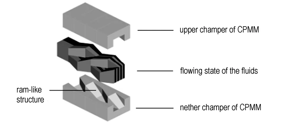
Fig.1 The emulsification principle of the CPMM
(2) Metal mesh embedded micromixer
The MMEM was made of stainless steel tube, which was filled with 200 mesh barbed wire. The length of the tube was 8 cm, while the external diameter was 1/8 inch. The area of the barbed wire was 2 m2, set as spiral. The mixing principle of the MMEM is very close to conventional large-scale static mixers used in the chemical industry[20].
(3) Viscometer
The viscometer used in the experiment was from Brookfield Engineering, DV-Ⅱ+pro. The test temperature was 55 ℃, the rotor model was 94#, and the rotate speed was 30 rpm.
2.3 Emulsification Experiment
The water phase(80 ℃) and the oil phase(50 ℃) were respectively transported into the micromixers by two gear constant flow pumps with pressure sensors( pressure tolerance kept within 15 MPa). The oxidizer solution to oil phase feeding ratio into the micromixers was always set at 9∶1. The MMEM and the CPMM were connected with stainless steel pipe to complete the emulsification of emulsion matrix together. Table 1 shows the experiment 1-5. As shown in experiment 5 of the Table 1, 2*CPMM-V1.2-R600 represents that two CPMM-V1.2-R300 were connected by the stainless steel pipe to complete the second emulsion together, which was almost double of the length of the microchannel of the caterpillar split-recombine micromixer. In experimental 2, two CPMM-V1.2-R300 were connected together to complete the first emulsion.
Table 1 The experiment 1-5
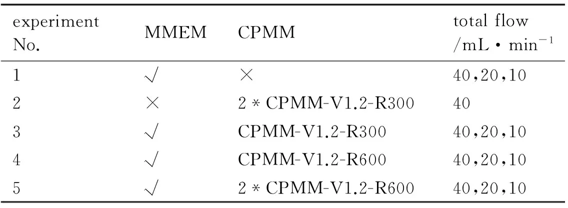
experimentNo.MMEMCPMMtotalflow/mL·min-11√×40,20,102×2*CPMM-V1.2-R300403√CPMM-V1.2-R30040,20,104√CPMM-V1.2-R60040,20,105√2*CPMM-V1.2-R60040,20,10
Note: √ indicates the instrument is applied to the corresponding experimental, while × indicates the instrument is not applied.
2.4 Properties Measurement of Emulsion Matrix
2.4.1 Viscosity of the Emulsion Matrix
Viscosity is one of the important properties of the emulsion matrix for industrial applications. In a certain range, as other properties being constant, the larger the viscosity of the emulsion matrix, the better the quality will be.
2.4.2 Droplet Diameter Distribution of Water Phase
The emulsion matrix particle diameter is a fundamental quality indicator of emulsion matrix. The smaller the diameter, the higher the interfacial energy of emulsion matrix is, indicating that the micromixers convert more energy from the pumps to the emulsion matrix.
The emulsion matrix was dissolved in cyclohexane, and the oxidant solution droplets could be observed at 400 times optical microscope. The optical microscope used in the experiment was from Nikon Corporation of Japan, Nikon eclipse 55i. The diameter distributions were estimated from the microphotographs of the microscope, using the software of image pro plus v7.0, which was from Lubrizol.
2.4.3 Dissolution Loss Rate of Ammonium Nitrate

The dissolved loss rate of AN is defined as
In the above equation,εis the dissolution loss rate of AN, %;Vis the volume of sodium nitrate, mL;Nis the molarity of sodium nitrate, 0.02 mol·L-1,Ckiois the mass fraction of AN in emulsion matrix, %; andmkiois the mass of emulsion matrix, g.
3 Experimental Results and Analysis
3.1 Pressure Drop and Viscosity
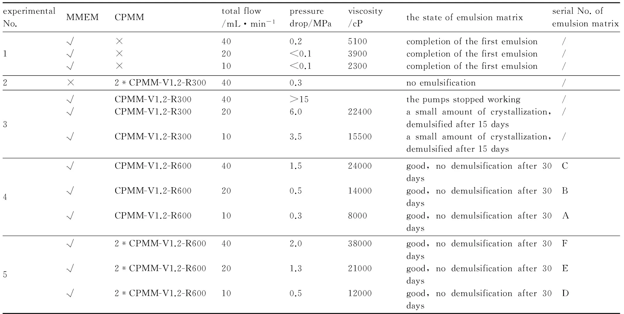
Table 2 shows the pressure drop measured by the pressure sensor at the gear constant flow pump, the viscosity and the state of the emulsion matrix in different experiments. In the table, five experiments are given and only experiments 4 and 5 produced good quality emulsion matrix, which was given a serial No A to F.
Table 2 The pressure drop, the viscosity and the state of the emulsion matrix in different experiment programs
experimentalNo.MMEMCPMMtotalflow/mL·min-1pressuredrop/MPaviscosity/cPthestateofemulsionmatrixserialNo.ofemulsionmatrix1√√√×××4020100.2<0.1<0.1510039002300completionofthefirstemulsioncompletionofthefirstemulsioncompletionofthefirstemulsion / / /2×2*CPMM-V1.2-R300400.3noemulsification /3√√√CPMM-V1.2-R300CPMM-V1.2-R300CPMM-V1.2-R300402010>156.03.52240015500thepumpsstoppedworkingasmallamountofcrystallization,demulsifiedafter15daysasmallamountofcrystallization,demulsifiedafter15days / / /4√√√CPMM-V1.2-R600CPMM-V1.2-R600CPMM-V1.2-R6004020101.50.50.324000140008000good,nodemulsificationafter30daysgood,nodemulsificationafter30daysgood,nodemulsificationafter30days C B A5√√√2*CPMM-V1.2-R6002*CPMM-V1.2-R6002*CPMM-V1.2-R6004020102.01.30.5380002100012000good,nodemulsificationafter30daysgood,nodemulsificationafter30daysgood,nodemulsificationafter30days F E D
As shown in Table 2, in experiment 1, the MMEM completed the first emulsion excellently, produced the emulsion matrix with the viscosity from 2300 to 5100 cP under the total flow from 10 to 40 mL·min-1. Due to its complex internal structure, the MMEM, in which tremendous work pressure will be generated as emulsifying high viscocity fluids, isn′t suitable for the second emulsion. In experiment 2, when the CPMM was used alone to complete the first emulsion, there was no emulsification, but in experiments 4 and 5, the MMEM and CPMM were used to complete the first and second emulsion separately, the second emulsion was completed very well, which demonstrated that the caterpillar split-recombine micromixer was suitable for the second emulsion, but not for the first emulsion. So using two types of micromixers to complete the first and second emulsion respectively is wise and feasible.
The CPMM failed to complete the first emulsion, but completed the second emulsion for higher viscosity fluids successfully, which demonstrated that the emulsification principle of split-recombine wasn′t achieved in it. When the viscosity of fluids increases, the pressure would increase in the microchannel, which would promote the shear effect of microchannel to fluids[21]. It is concluded that for high viscosity fluids, the emulsification principle of the CPMM is the shear effect of microchannel to fluids.
The width of microchannel of CPMM-V1.2-R300 is 300 microns, while CPMM-V1.2-R600 is 600 microns.
In experiment 3, when CPMM-V1.2-R300 was used to complete the second emulsion, the pressure drop was too high, and exceeded the tolerance range of the pump at the total flow of 40 mL·min-1. Through the comparison of the results of experiments 3 and 4 (the difference of them was just the width of the microchannel of CPMM), it is concluded that the width of the microchannel affects the pressure drop of emulsification significantly, and excessive pressure drop will result in the demulsification of emulsion matrix When the emulsion pressure was higher than 3.5 MPa, a small amount of crystals of AN appeared in the emulsion matrix. From 10 mL·min-1to 40 mL·min-1of the total flow, CPMM-V1.2-R600 was more suitable than CPMM-V1.2-R300 for the emulsification of emulsion matrix.
As can be seen from experiment 4, within the scope of 10 mL·min-1to 40 mL·min-1of the total flow, the emulsion matrix with the viscosity from 8000 to 24000 cP was produced. In experiment 5, two CPMM-V1.2-R600s were used to increase the length of the microchannel, and under the total flow rate of 40 mL·min-1, a good quality emulsion matrix with the viscosity of 38000 cP was produced under the total flow of 40 mL·min-1. The bigger the flow velocity, the higher the viscosity of the emulsion matrix is and the better the quality is. Through the comparison of the results of experiments 4 and 5, it is concluded that the increasing of the length of microchannel will raise the pressure drop of the emulsification and improve the emulsion quality.
3.2 Droplet Diameter Distribution of Water Phase
Through the method mentioned in section 2.4.2, emulsion matrix particle diameter distribution of water phase of the emulsion matrix with different serial number in the experiment could be estimated. Fig.2, Fig.3 and Fig.4 are the histograms of the droplet diameter distribution of water phase.
The emulsion matrix particle diameter distribution of water phase reflects the energy of the micromixers converted to the emulsion matrix. The smaller the diameter is, the bigger the specific surface area is and the higher the energy of emulsion matrix is, meanwhile, the smaller the standard deviation and the variance are, the more uniform the emulsification is. The influence of the flow velocity and the length of microchannels on the quality of emulsification were studied in experiments 4 and 5. The average values of the emulsion matrix A to F were 9.650, 6.519, 3.223, 8.975, 5.207, 1.895 μm, respectively.
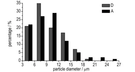
Fig.2 Droplet diameter distribution of water phase (A, D represent serial No. of emulsion matrix, same as in Table 2)
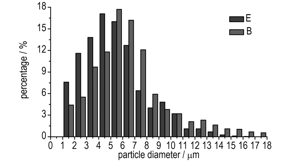
Fig.3 Droplet diameter distribution of water phase (B, E represent serial No. of emulsion matrix, same as in Table 2)
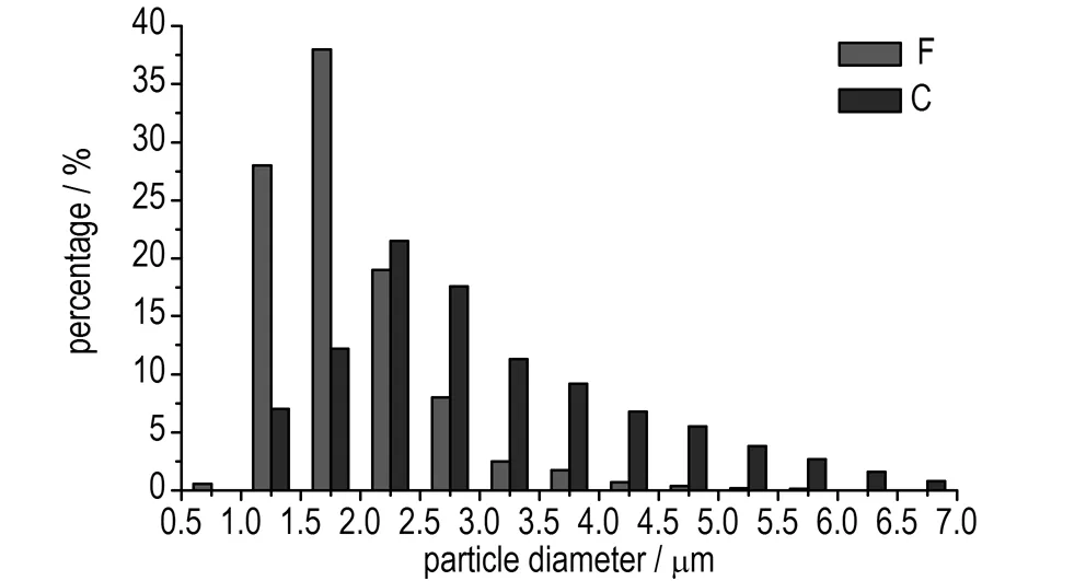
Fig.4 Droplet diameter distribution of water phase (C, F represent serial No. of emulsion matrix, same as in Table 2)
As can be seen from Fig.2, through the comparison of A and D, it is concluded that the length of microchannels has significant influence on the emulsion matrix particle diameter distribution of water phase. The longer the length is, the smaller the diameter and standard deviation are, and the better the emulsion quality is. The same conclusions were obtained through the comparison of B and E from Fig.3, and the comparison of C and F from Fig.4. As shown in Fig.4, the droplet diameter of the emulsion matrix F distributed between 1.0 μm to 2.5 μm mostly with the average values of 1.895 μm, which reflected a good quality.
As also can be seen from Fig.2 to Fig.4, through the comparison of A, B, and C, and the comparison of D, E, and F, it is concluded that the flow velocity has significant influence on the emulsion matrix particle diameter distribution of water phase, the bigger the flow velocity is, the smaller the diameter and standard deviation are, and the better the emulsion quality is.
3.3 Dissolved Loss Rate of Ammonium Nitrate
Table 3 shows the dissolution loss rate of AN of emulsion matrix with different serial number after 30 days′ storage at room temperature.
Table 3 The dissolution loss rate of AN of emulsion matrix

serialNo.ofemulsionmatrixABCDEFdissolutionlossrate/%0.38510.32870.30370.27900.26160.2497
The dissolution loss rate of AN reflects the storage performance of emulsion matrix. As can be seen from Table 3, the emulsion matrix F, produced in experiment 5, the dissolution loss rate of AN was 0.2497% after 30 days storage at room temperature, which reflected a good quality. Through the comparison of A, B, and C, and the comparison of D, E, and F, we can conclude that the increase of fluid flow velocity in the emulsification can raise the storage performance of the emulsion matrix. Through the comparison of A and D, B and E, C and F, we can conclude that the longer the length of microchannel, the better the storage performance of the emulsion matrix is.
As the flow velocity increasing, the shear effect of the microchannel to the fluids will be bigger, reducing the emulsion matrix particle diameter. When the materials of emulsification were not changed, the smaller the emulsion matrix particle diameter was, the higher the viscosity of emulsion matrix and the better the storage performance. The increase of the fluid flow velocity will raise the mixing intensity of microchannel to fluids, which will make the emulsification more uniform. However, in the second emulsion, the fluid viscosity is so high that the strong fluid disturbance will not appear. So at this moment, the influence of the fluid flow velocity on the quality of the emulsion is the shear effect, rather than the mixing intensity.
As the length of the microchannel increases, the pressure drop of the microchannel will be bigger, so as to the shear effect. Meanwhile, the increase of the length of the microchannel will rises the residence time of the fluid in the microchannel, which will make the emulsification more uniform.
In experiment 5, the MMEM was connected with two CPMM (CPMM-V1.2-R600) to complete the first emulsion and the second emulsion separately. Under the conditions of the total fluid flow was 40 mL·min-1and the pressure drop was 2 MPa, the micromixers produced a good quality emulsion matrix in the experiment, whose viscosity was 38000 cp and average emulsion matrix particle diameter was 1.895 μm. The dissolution loss rate of AN was 0.2497% after 30 days storage at room temperature. For the preparation of emulsion matrix, the microchannel of micromixer deposit small amount of explosives, there is no possibility of accidental detonation. And there is no moving part in the microchannel, which will greatly improve the security of emulsification process.
4 Conclusions
Different types of micromixers are suitable for different stages of the emulsification. It is wise and feasible to complete the first and second emulsion respectively through two types of micromixers (MMEM and CPMM). Under the conditions of the total fluid flow was 40 mL·min-1, the two micromixers produced a good quality emulsion matrix in the experiment, and its viscosity was 38000 cP and average droplet size of dispersed phase was 1.895 μm. The dissolution loss rate of AN was 0.2497% after 30 days storage at room temperature.
The emulsification principle of the CPMM for high viscosity fluids is the shear effect of the microchannel to the fluids. The width of the microchannel affects the pressure drop of emulsification significantly, and excessive pressure drop will result in the demulsification of emulsion matrix. In a certain range, increasing the microchannel length and fluid flow velocity can decrease the dissolution loss rate of AN and particle diameter of the emulsion matrix, and increase the viscosity of the emulsion matrix.
[1] WANG Xu-guang. Emulsion Explosives [M].Second Edition. Beijing: Metallurgical Industry Press, 2008: 195-226.
[2] Duffy N, Blonk H C G, Beindorff C M,et al. Organogel-based emulsion systems, micro-structural features and impact on in vitro digestion[J].JournaloftheAmericanOilChemists′Society, 2009, 86(8): 733-741.
[3] Ehrfeld W, Golbig K, Hessel V, et al. Characterization of mixing in micromixers by a test reaction: single mixing units and mixer arrays[J].IndustrialandEngineeringChemistryResearch,1999, 38(3): 1075-1082.
[4] Sugiura S, Nakajima M, Iwamoto S, et al. Interfacial tension driven monodispersed droplet formation from microfabricated channel array[J].Langmuir, 2001, 17(18): 5562-5566.
[5] Ehlers S, Elgeti K, Menzel T, et al. Mixing in the offstream of a microchannel system[J].ChemicalEngineeringandProcessing, 2000, 39(4): 391-398.
[6] Fu X, Liu S F, Ruan X D, et al. Research on staggered oriented ridges static micromixers[J].SensorsandActuatorsB, 2006, 114(2): 618-624.
[7] Matsuyama K, Mine K, Kubo H, et al. Design of micromixer for emulsification and application to conventional commercial plant for cosmetic[J].ChemicalEngineeringJournal, 2011, 167(2-3): 727-733.
[8] Ziegenbalg D, Kompter C, Schönfeld F, et al. Evaluation of different micromixers by CFD simulations for the anionic polymerization of styrene[J].GreenProcessingandSynthesis, 2012, 1(2): 211-223.
[9] Hossain S, Ansari M A, KimK-Y. Evaluation of the mixing performance of three passive micromixers[J].ChemicalEngineeringJournal, 2009, 150(2-3): 492-501.
[10] Pennemann H, Hardt S, Hessel V, et al. Micromixer based liquid/liquid dispersion[J].ChemicalEngineeringandTechnology, 2005, 28(4): 501-508.
[11] Havekamp V, Ehrfeld W, Gebauer K, et al. The potential of micromixer for contacting of disperse liquid phases[J].Fresenius′JournalofAnalyticalChemistry, 1999, 364(7): 617-624.
[12] Cherlo SKR, Kariveti S, Pushpavanam S. Experimental and numerical investigation of two-phase (liquid-liquid) flow behavior in rectangular microchannels[J].IndustrialandEngineeringChemistryResearch, 2010, 49(2): 893-899.
[13] Nguyen N T, Wu Z J. Micromixers-a review[J].JournalofMicromechanicsandMicroengineering, 2005, 15(2): 1-16.
[14] Hessel V, Löwe H, Schönfeld F. Micromixers-a review on passive and active mixing principles[J].ChemicalEngineeringScience, 2005, 60(8-9): 2479-2501.
[15] Tromeur M, Mahé C, Schwesinger N, et al. Micromixers to produce cosmetic emulsions[J].InternationalJournalofCosmeticScience, 2003, 25(1-2): 1-4.
[16] Goodridge RJ, Sujansky V, Junarsa I, et al. Process for the production of intermediate emulsions for use in emulsion explosives: US, 20130327456[P]. 2013, 12, 12.
[17] Schwesinger N, Frank T, Wurmus H. A modular microfluid system with an integrated micromixer[J].JournalofMicromechanicsandMicroengineering, 1996, 6(1): 99-102.
[18] Mae K, Maki T, Hasegawa I, et al. Development of a new micromixer based on split/recombination for mass production and its application to soap free emulsifier [J].ChemicalEngineeringJournal, 2004, 101(1-3): 31-38.
[19] Ansari M A, Kim K Y, Anwar K, et al. A novel passive micromixer based on unbalanced splits and collisions of fluid streams[J].JournalofMicromechanicsandMicroengineering, 2010, 20(5): 055007.
[20] Bertsch A, Heimgartner S, Cousseau P, et al. Static micromixers based on large-scale industrial mixer geometry[J].LabonaChip, 2001, 1: 56-60.
[21] Schwolow S, Hollmann J, Schenkel B, et al. Application-oriented analysis of mixing performance in microreactors[J].OrganicProcessResearchandDevelopment, 2012, 16(9): 1513-1522.
- 含能材料的其它文章
- Synthesis and Characterization of Two New Energetic Polyamino and Nitro Pyridine Derivatives
- 《含能材料》2015年(第23卷)总目次
- Non-isothermal Decomposition Kinetics,Specific Heat Capacity and Adiabatic Time-to-explosion of Cu(pn)2(FOX-7)2
- Facile Synthesis and Crystal Structure of 3,4-Bis(1H-5-tetrazolyl)furoxan
- Synthesis and Properties of N,N-Bis((3,5-dinitro-1H-1,2,4-triazol-1-yl)methyl) nitramine
- Comparison with Molecular Surface Electrostatic Potential and Thermal Reactivity of Nitramines

