Hydroelastic Analysis of a Very Large Floating Structure Edged with a Pair of Submerged Horizontal Plates
MA Zhe, CHENG Yong, ZHAI Gangjun, and OU Jinping
Deepwater Engineering Research Center,Dalian University of Technology,Dalian116024,P. R. China
Hydroelastic Analysis of a Very Large Floating Structure Edged with a Pair of Submerged Horizontal Plates
MA Zhe, CHENG Yong*, ZHAI Gangjun, and OU Jinping
Deepwater Engineering Research Center,Dalian University of Technology,Dalian116024,P. R. China
This paper is concerned with the hydroelastic problem of a very large pontoon-type floating structure (VLFS) edged with a pair of submerged horizontal plates, which is a combination of perforated and non-perforated plates attached to the for-end and back-end of the VLFS. For the hydroelastic analysis, the fluid is assumed to be ideal and its motion is irrotational so that a velocity potential exists. The VLFS is modeled as an elastic plate according to the classical thin plate theory. The fluid-structure interaction problem is separated into conventional hydrodynamics and structure dynamics by using modal expansion method in the frequencydomain. It involves, firstly, the deflection of the VLFS, which is expressed by a superposition of modal functions and corresponding modal amplitudes. Then the boundary element method is used to solve the integral equations of diffraction and radiation on the body surface for the velocity potential, whereas the vibration equation is solved by the Galerkin’s method for modal amplitudes, and then the deflection is obtained by the sum of multiplying modal functions with modal amplitudes. This study examines the effects of the width and location of the non-perforated horizontal plates on the hydroelastic response of the VLFS, then the performance of perforated plates is investigated to reduce the motion near the fore-end of the VLFS. Considering the advantages and disadvantages of submerged plates without and with cylindrical holes, we propose a simple anti-motion device, which is a combination of a pair of perforated and non-perforated plates attached to the for-end and back-end of the VLFS. The effectiveness of this device in reducing the deformation and bending moment of the VLFS has been confirmed, and is compared with the results in cases without and with the submerged horizontal plates by the analysis in this paper.
VLFS; anti-motion device; hydroelastic problems; perforate horizontal plate; submerged horizontal plate
1 Introduction
Mat-like very large floating structure (VLFS) is regarded as an alternative option of utilizing ocean space such as floating airports, oil storage vessels, floating artificial island,etc.A general floating structure, such as breakwater, oceanic platform, floating wind turbine, that has sufficient rigidity is usually assumed to be a rigid body, and structural and hydrodynamic analysis are solved separately. However, the horizontal dimensions of VLFS are much larger than its vertical dimensions, and the elastic response will become dominant over the rigid motion. Thus the fluid-structure interaction problem is significant and is proposed (e.g., Wu, 1984; Price and Wu, 1985; Bishopet al., 1986). To tackle this problem, various analytical approaches and numerical approaches such as the eigenfunction expansion-matching method (e.g., Karmakar and Guedes Soares, 2012; Zhaoet al., 2008; Liet al., 2011; Watanabeet al., 2006), the boundary element method (BEM) (Yanet al., 2003; Kashiwagi, 1999), the finiteelement method (FEM) (Fujikuboet al., 1997), and thehybrid finite element-boundary element (FE-BE) method (Tayet al., 2007; Gaoet al., 2011; Riyansyahet al., 2010; Kimet al., 2007) have been presented in previous studies.
The VLFS may sometimes be placed in a location where the sea state is rather harsh, and thus some ways to reduce the responses of a VLFS impacting on the floating structure are proposed. The traditional way is by building a breakwater around the VLFS to reduce the height of the incident wave (e.g., A OWC breakwater system jointing the VLFS by a pin has been presented by Hong and Hong, 2007). However, many cases such as the environmental protection, construction time and economics restrict the development of the upright breakwater, and dynamic characteristics of the mooring system like floating breakwater have complex effects on the floating body. Following these consideration, Takagiet al.(2000) proposed a simple anti-motion device with a reduction of wavetransmission from the outside to inside of VLFS. The wave response analysis of a VLFS, of which a submerged horizontal plate is attached at the fore-end, has been analyzed by Watanabeet al.(2003). Phamet al.(2008) have been concerned with the hydroelastic analysis of a pontoon-type, very large floating structure (VLFS) with a horizontal submerged annular plate attached around itsperimeter.
In this paper, the hydroelastic response of a VLFS edged with a pair of submerged horizontal plates is analyzed by using modal expansion method. Firstly, the hydroelastic response of a VLFS, where two non-perforated horizontal plates are attached at the fore-end and backend respectively, are presented according to the changes of width and depth below the surface of the water of the anti-motions. Then we investigate the effectiveness of two perforated horizontal plates in reducing vertical deflections as well as bending moment under wave action. Finally, we propose an anti-motion device of a pair of perforated and non-perforated plates, which are attached to the fore-end and back-end of VLFS, and compare the obtained results for the VLFS without and with submerged plates. Numerical results have been presented to show the hydroelastic response reduction performance of the combination anti-motion devices of perforated and non-perforated plates. The main contributions of this paper are the following: 1) We investigate the sensitivity of the width and installation depth of the submerged plate anti-motion device in reducing vertical deflections under wave action. 2) In order to mitigating the hydroelastic response near fore-end of the VLFS, the effectiveness of perforated plates is presented. 3) Comparing the advantage and disadvantages of the non-perforated and perforated horizontal plates, we propose a simple anti-motion, which is combination of a pair of perforated and nonperforated horizontal plates attached to the for-end and back-end of the VLFS. And its effectiveness is clearly observed.
2 Mathematical Formulation
2.1 Plate-Water Model
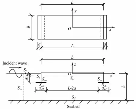
Fig.1 Geometry of a rectangular VFLS with two submerged horizontal plates and coordinate system.
Fig.1 shows the fluid-structure problem and Cartesian coordinate system. Thez-axis is pointing upwards, and thex-yplane is on the mean position of the free water surface, wherehis the depth, andAis the amplitude of the incident wave. The whole fluid domain is defined at Ω which contains the bottom of the VLFSSb, side of the VLFSSs, the surfaces of the submerged horizontal platesSauandSab, the free surfaceSf, the seabedSdand the infinite cylindrical surfaceS∞. The VLFS has a lengthL, widthB, heighthv, anddis the draft of the VLFS inzdirection. The two horizontal plates of the width 2aare attached at the fore-end and the back-end of the VLFS at the submerged depth ofd1, respectively. An incident wave of circular frequencyωenters the computational domain at an angleθ=θ0. The problem at hand is to discuss the effectiveness of the submerged horizontal plate in reducing the deflections and bending moment of the VLFS under wave action, and improve the constitution of plates which is attached at the VLFS.
2.2 Equations of Motion for Water
Assuming irrotational motions of ideal fluid, we formulate the boundary value problem for velocity potential Φ(x,y,z,t). Considering time-harmonic motions with the complex time dependence e-iωtbeing applied to all firstorder oscillatory quantities, the following expressions can be made:
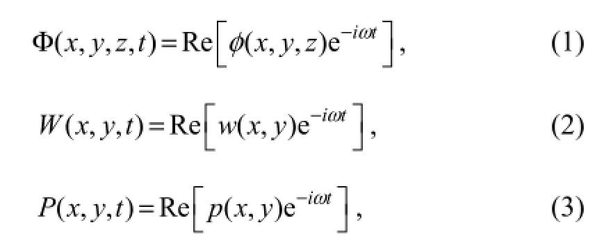
whereW(x,y,t) andP(x,y,t) are the vertical deflection and fluid pressure on the VLFS respectively,w(x,y) andp(x,y) are the complex displacement and complex pressure respectively, and the complex velocity potentialφ(x,y,z)is governed by the Laplace’s equation

in the fluid domain. The potential must satisfy the following boundary conditions on the free water surface, on the sea-bed, on the infinite cylindrical surface, on the wetted bottom surface of the VLFS and on the submerged horizontal annular plate respectively:
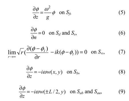
whereIφis the incident potential,nis unit normal vector (the positive direction points out of the fluid domain),ris the horizontal distance between reference point and the origin,kis the wave number. The following dispersion equation can be obtained:

2.3 Equations of Motion for VLFS
It is now widely accepted that VLFS response in terms of the vertical deflection can be captured well by modeling the whole VLFS as an elastic plate. In this formulation with assuming the VLFS as an elastic, isotropic, thin plate, the motion of the floating body is governed by the equation of a thin plate resting on a uniform elastic foundation:

whereDis the bending rigidity,Eis modulus of elasticity,Iis the cross sectional moment of inertia, andQ(x,y,t) is the lateral load per unit area as given by

wheremsdenotes the mass per unit area of the VLFS,W(x,y,t) andP(x,y,t) being defined as above. By substituting Eqs. (2), (3) and (12) into the Eq. (11), the motion equation for the VLFS can be obtained:

The floating body is not constrained in the vertical direction and along its edges, and the following boundary conditions for a free edge must be satisfied:
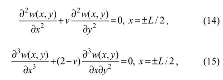
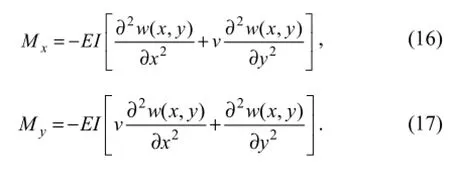
wherevis Poisson’s ratio. The bending momentMxandMycan be calculated from the following relations:
2.4 Modal Expansion of VLFS Motion and Velocity Potential
Eq. (13) indicates that the deflection of the VLFS,w(x,y), is coupled with the fluid motion (or velocity potential,φ(x,y,z)). On the other hand, the fluid motion can be obtained only when the VLFS responsew(x,y) is specified in the boundary condition, Eqs. (8) and (9). In order to decouple this interaction problem into the hydrodynamic problem in terms of the velocity potential and a plate vibration problem in terms of the generalized displacement, we adopt the modal expansion method as proposed by Newman (1994). In this method, the response of the VLFSw(x,y) is expanded by a series of the products of the modal functionsfj(x,y) and the complex amplitudesζj:

The potentialφ(x,y,z)can be expressed by the sum of the incident potentialφI(x,y,z), the diffraction potentialφD(x,y,z)and the radiation potentialφR(x,y,z)based on the linear theory. The radiation potentialφR(x,y,z)can be further decomposed as follows:

wherejφis the radiation potential corresponding to the unit-amplitude motion of thel-th modal function, the diffraction potentialφD(x,y,z)is for the outgoing wave from the body which is assumed to be fixed, and the incident potentialφI(x,y,z)is given as follows:

By substituting Eqs. (18) and (19) into Eqs. (5)-(9), we can obtain the Laplace’s equation and boundary conditions for fluid in the decoupled form,i.e.,
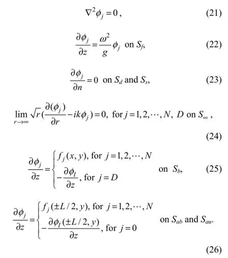
Thus, the boundary value problems for each of the unit-amplitude radiation potentials and the diffraction potential are given explicitly in an uncoupled form.
3 Numerical Discretization
3.1 Hydrodynamic Analysis
The boundary value problems given by Eqs. (21)-(26) can be solved by using the Green’s second identity. The resulting boundary integral equation is

where (x0,y0,z0) and (x,y,z) represent the source and field point, respectively.G(x,y,z,x0,y0,z0) is a free- surface Green’s function for water of finite depth that satisfies the seabed boundary condition, water free surface boundary condition and boundary condition at infinity. The integral form can be represented as follows (John, 1950):
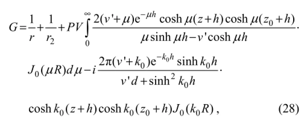
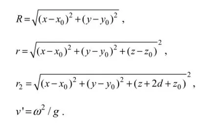
whereJ0denotes the Bessel function of the first kind and order zero,v' is the wave number at infinite depth sea,Rdenotes the horizontal distance between field and source point,rdenotes the distance between field and source point, andr2denotes the distance between field and the mirror image of the source field about water surface. These quantities can be given as
The fluid pressurep(x,y) from Eq. (13) relates to the velocity potential on the bottom of the VLFS may be obtained

3.2 Solution for Equation of Motion
We substitute the fluid pressure and the vertical deflection (Eqs. (29) and (18)) into the vibration equation of the VLFS ( Eq. (13)) to obtain the motion equation

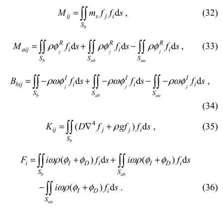
In the above equation, we apply the Galerkin’s method, where we multiply both sides of the Eq. (30) byfi(x), and integrate the resultant equation over the bottom of the VLFS. The result of this transformation takes the form:

where the generalized massMij, the generalized added massMaij, the generalized added dampBbij, the generalized stiffnessKij, and the generalized exciting forceFiare given as follows,
By substituting these modal amplitudesζjinto the Eq. (18), one finally obtains the deflection of the VLFS.
3.3 Modal Functions
The modal functionfj(x,y) of the VLFS can be expressed by the product of modal function inxdirection and modal function inydirection, thus a case study of a beam model with free end is discussed as follows. The procedures mentioned above are mathematically valid for arbitrarily chosen modal function. However, in order to guarantee the convergence of the solutions, the appropriate choice of the modal functions is essential. In this paper, we employ the following modal functions (dry-modal functions) combining the rigid body motions and the sinusoidal functions because they satisfy the free-end condition of the beam and their convergence has already been proved by Eatock Taylor (2003) and Etaock Taylor and Ohkusu (2000):

wheref1(x) andf2(x) are the modes corresponding to the rigid-body motions, namely heave and pitch, respectively;fj+1(x) (j=2, 3,…) are the elastic modes.
4 Results and Discussions
4.1 Verification of Numerical Model
The validity and accuracy of the present formulation and method for solving the VLFS are established by comparing our numerical results without submerged plates against experimental results obtained by Maedaet al.(1995) and numerical results solved by Teng and Gou (2006). The modal functions which are employed in this paper and by Teng and Gou (2006), are sinusoidal and cosinusoidal functions respectively. The pertinent information for the VLFS design used by Maedaet al.(1995) is given in Table 1.
Based on convergence texts, it is found that the size of the plate element must be smaller thanλ/10 (λis the wavelength) for accurate prediction of the deflection and moment resultants. Figs.2-3 show the vertical deflection along the longitudinal centerline of the VLFS with the head sea edge of the VLFS having maximum deformation for two cases of wavelength (i.e.,λ=2 m and 4 m). It is seen that for short wavelength our calculated results near the fore-end are in good agreement with the experimental results obtained by Maedaet al.(1995), and the results predicted by Teng and Gou (2006) at the back-end are in more agreement with the experimental results obtained by Maedaet al.(1995). This is mainly due to the differently chosen modal functions. However, for long wavelength we can observe satisfactory agreement of our calculated results with the experimental results obtained by Maedaet al.(1995) and those predicted by Teng and Gou (2006), and verify the validity of the present formulation and numerical method in evaluating the hydroelastic response of the VLFS. Note that the deformation for short wavelength is larger than those for long wavelength.

Table 1 Main parameters of experiment model
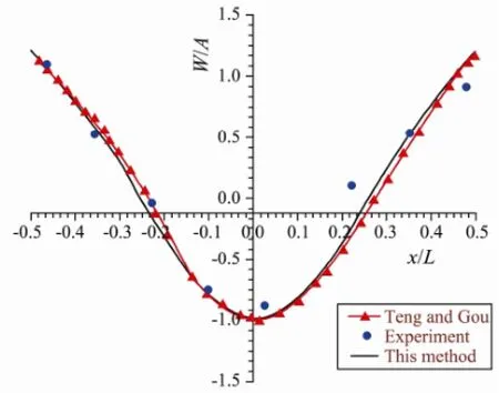
Fig.3 Deflection distribution of floating structure at wave length 4 m.
4.2 VLFS with Two Attached Submerged Horizontal Plates
We analyzed the hydroelastic response of the VLFS with two attached submerged horizontal plates, at the fore-end and back-end of VLFS respectively. The VLFS has a lengthL=4 m, widthb=0.733 m, heighthv=0.01 m, draftd=0.005 m, bending rigidityD=50.832 Nm, and poisson’s ratio=0.3. It is assumed that the water depthh=0.5 m, and the incident wave lengthλ=1.0 m. In order to study the sensitivity of the level of the submerged plates, we analyzed the hydroelasticity of the VLFS without and with submerged horizontal plate having a width of 2a=0.12 m, 0.16 m, 0.18 m, 0.20 m and 0.24 m. Figs.4-5 only show the dimensionless deflections (|W(x)|/A) and the dimensionless bending moments (M(x)/(ρgLBhA)) of the VLFS without and with the submerged plates of width 2a=0.20 m and placed at various depths fromd1=0.15 to 0.25 m. For other widths, the effectiveness of the submerged plates has the same trend. It is seen that as the depth of the two submerged plates increases from 0.15 to 0.25 m, the hydroelastic deflection and bending moment in the VLFS decrease as compared with its counterpart without anti-motion plate. From these results, the two submerged plates placed atd1=0.25 m give the best reduction.
In order to study the effect of the width of the two submerged horizontal plates on the deflection of the VLFS, we analyze the hydroelasticity of the VLFS without and with two submerged plates positioned at depthd1=0.25 m. Figs.6-7 show the deflection and bending moment amplitudes of the VLFS without and with the submerged plates having various widths 2a=0.12 to 0.24m and placed at depthd1=0.25 m. It can be seen that as the width of the submerged plates increases from 0.12 to 0.20 m, the deflection and bending moment decrease as compared with the results without plates. However when the width of the attached plates increase to 0.24 m, the effectiveness of the submerged plates in reducing the deflection and bending moment is insignificant. Note that as the width of the plates increase, the deflection and the bending moment of the VLFS is magnified near the foreend, and we can improve the effectiveness by increasing the depth of the submerged plates. Thus, the submerged plates with an 0.20 m width and positioned atd1=0.25 m give the best reduction.
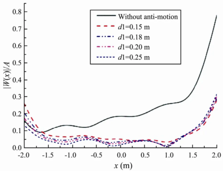
Fig.4 Deflection amplitude of the VLFS without and with two submerged plates of widths 2a=0.20 m at various depths.
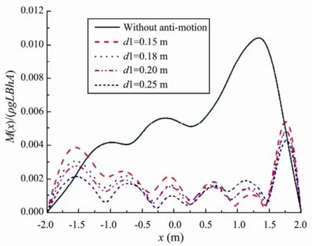
Fig.5 Bending moment amplitude of the VLFS without and with two submerged plates of widths 2a=0.20 m at various depths.
It is noted that the hydroelastic response of the VLFS with two submerged plates having a width 0.20 m and placed atd1=0.25 is magnified near the fore-end of the VLFS. In order to improve the efficiency of the submerged plates, we analyzed a VLFS with two submerged perforated plates (Fig.8) with a 4L2=0.20 m width and placed at 0.25 m, and the pertinent information for the VLFS is the same as above. The perforated horizontal plate has three rows of cylindrical holes along thexdirection and four rows of cylindrical holes along theydirection. These cylindrical holes have the same radiusR=0.014 m. Figs.9-10 shows the deflection and moment of the VLFS with the perforated horizontal plates compared with those results without and with the non-perforated horizontal plates having an 2a=0.20 m width and positioned atd1=0.25 m. It is seen that the effectiveness of the perforated horizontal plates in reducing the hydroelasticresponse near the fore-end of the VLFS is significant; however, the motion of the VLFS is magnified near the mid-position and back-end.
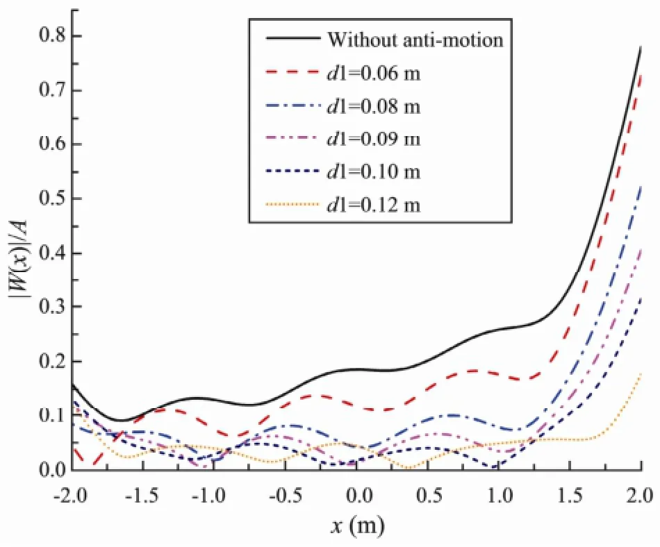
Fig.6 Deflection amplitude of the VLFS without and with two submerged plates of various widths at depth= 0.25 m.
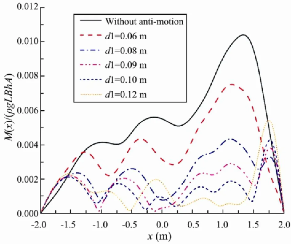
Fig.7 Bending moment amplitude of the VLFS without and with two submerged plates of various widths at depth=0.25 m.
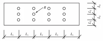
Fig.8 The design of the perforated plate.
Considering these advantages and disadvantages of submerged horizontal plates without and with cylindrical holes, we propose a simple anti-motion, which is combination of a pair of perforated and non-perforated plates attached to the for-end and back-end of the VLFS. The distance isd2=0.04 m between the perforated and nonperforated plate. The schematic diagram of the fluidstructure problem is shown as Fig.11. Figs.12-15 show the deflection and bending moment of the VLFS edged with a pair of perforated and non-perforated horizontal plates, which is here referred to as case 3, and the results are compared with those of VLFS without and with the submerged horizontal plates, which are here referred to as case 1 and case 2 respectively, for wavelengthλ=0.6 m and 1.0 m. It is clear that the hydroelastic responses of VLFS are decreased because of the employment of the perforated and non-perforated horizontal plates, and the effectiveness of the combination of perforated and nonperforated horizontal plates becomes clear.
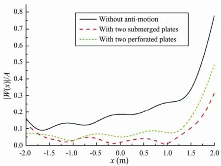
Fig.9 Deflection amplitude of the VLFS without and with anti-motion.
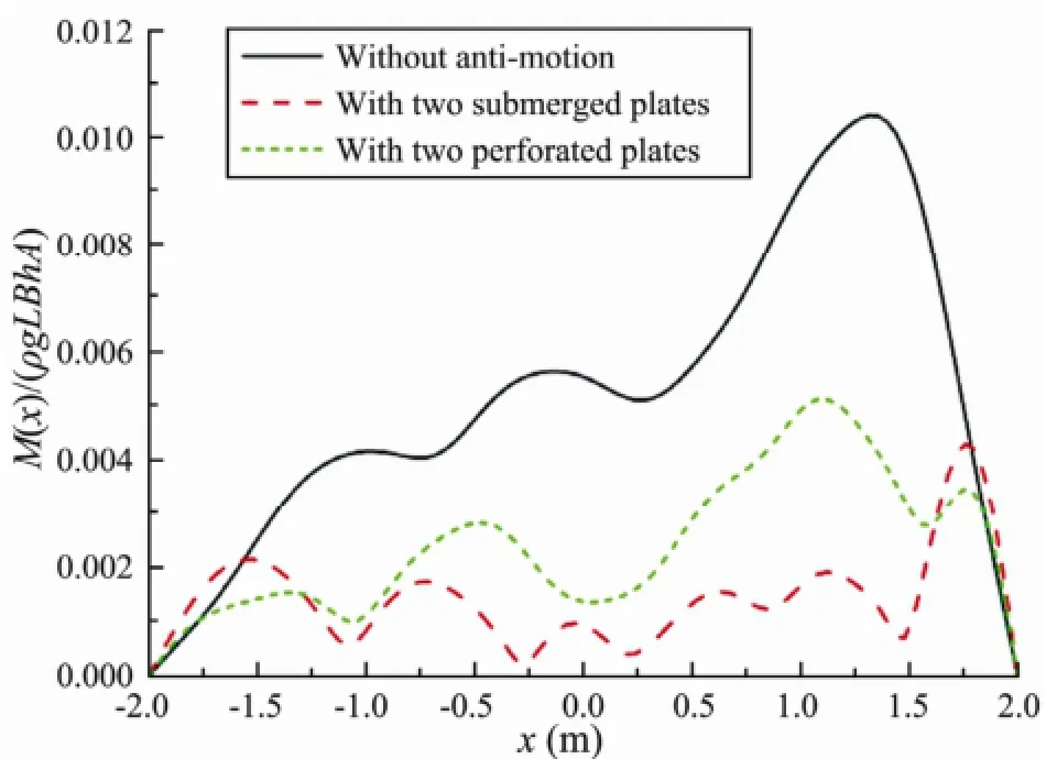
Fig.10 Bending moment amplitude of the VLFS without and with anti-motion.

Fig.11 Schematic diagram of the fluid-structure problem.
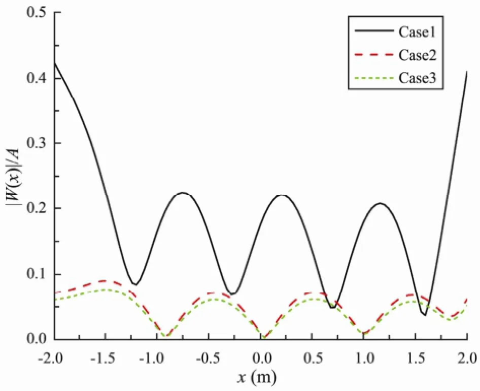
Fig.12 Deflection amplitude of the VLFS under three working conditions for wavelength 0.6 m.
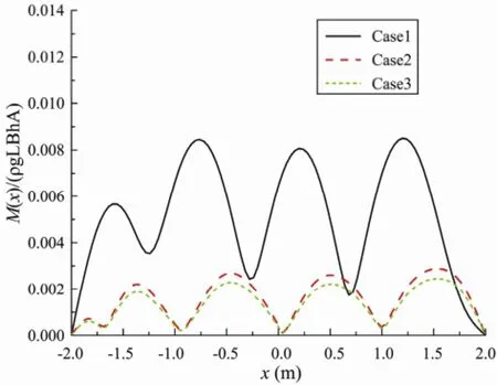
Fig.13 Bending moment amplitude of the VLFS under three working conditions for wavelength 0.6 m.
In order to take into account the variable wavelength in the hydroelastic responses, we analyzed a VLFS edged with a pair of perforated and non-perforated horizontal plates of 0.20 m width and placed atd1=0.25 m,d2=0.04 m. The results are compared with those of a VLFS without and with two submerged horizontal plates of 0.20 m width and placed atd1=0.25 m. Figs.16-18 show the hy-droelastic responses at the fore-end, mid-position and back-end of the VLFS in the three cases, mentioned above. That the effect of the response reduction of the combination of the perforated and non-perforated horizontal plates compared with the results without and with two submerged horizontal plates can be clearly observed. Note that the effect of response reduction of the simple anti-motion device is clearly observed in short wavelength region. On the other hand, the motion of the VLFS is magnified in long wavelength region with the attachment of the simple anti-motion device. However, in the real sea areas where the VLFS is adopted, the incident wave has its significant wave energy at least whenL/λ〉6 (Watanabeet al., 2003), thus the observed undesirable magnification of the motion will have no influence on the VLFS.
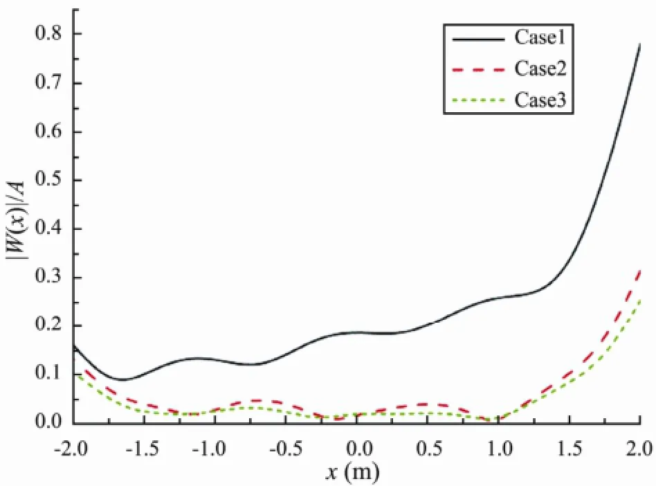
Fig.14 Deflection amplitude of the VLFS under three working conditions for wavelength 1.0 m.

Fig.15 Bending moment amplitude of the VLFS under three working conditions for wavelength 1.0 m.
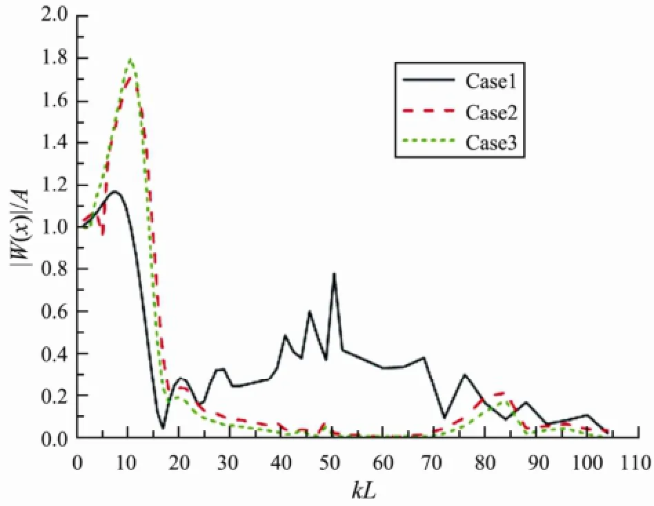
Fig.16 Deflection amplitude of the VLFS at for-end under three working conditions.
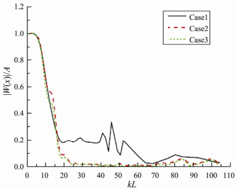
Fig.17 Deflection amplitude of the VLFS mid-position under three working conditions.
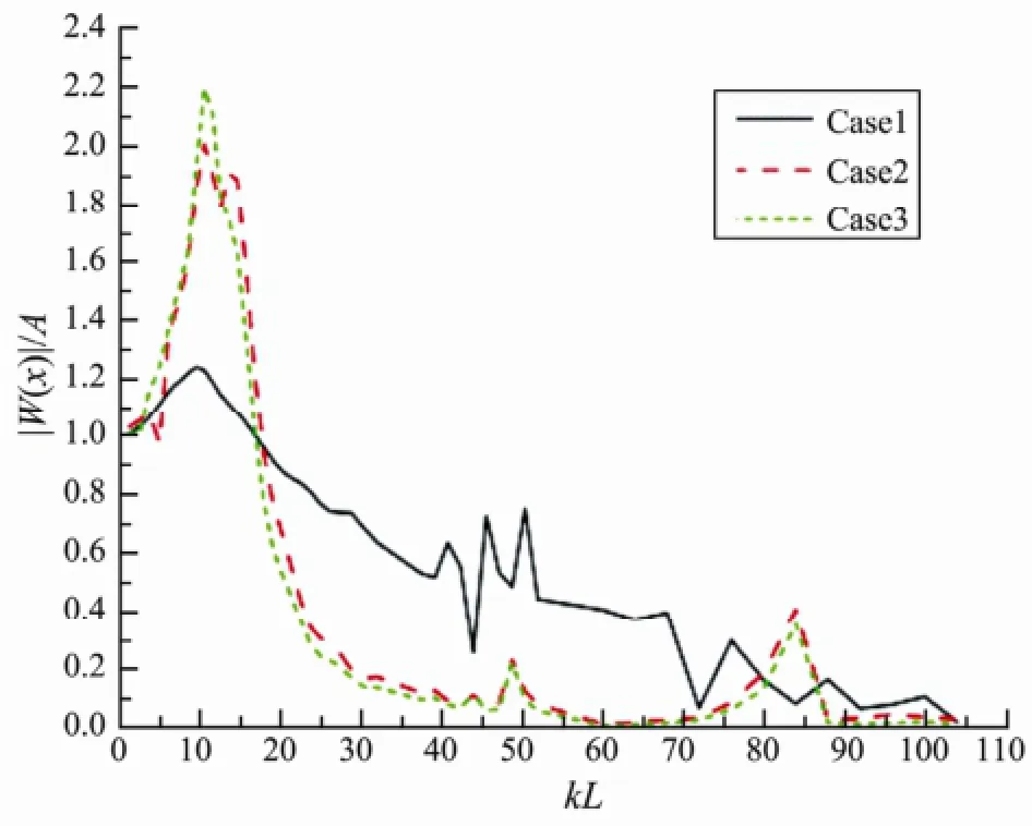
Fig.18 Deflection amplitude of the VLFS mid-position under three working conditions.
5 Concluding Remarks
In this paper, we have investigated the hydroelastic problem of the VLFS without and with the anti-motion device by using the modal expansion method. The effects of varying the width and the depth of installation of the submerged horizontal plates on the hydroelastic response are also discussed. It is found that the submerged perforated horizontal plate which has some cylindrical holes along thexandydirections, is the better anti-motion design for reducing the hydroelastic response near the fore-end of the VLFS when compared with the submerged non-perforated horizontal plate. However, the effectiveness of the non-perforated horizontal plates in reducing the hydroelastic response near the mid-position and backend of the VLFS is significant when compared with the submerged perforated plate.
Considering the motion reduction near the fore-end, mid-position and back-end of the VLFS, we propose a simple anti-motion, which is a combination of a pair of perforated and non-perforated horizontal plates attached to the for-end and back-end of the VLFS. The significant reduction effect of the response with the anti-motion device has been confirmed by the analysis. In the further work, these factors with the anti-motion, such as the number and radius of the cylindrical hole and the distance between the perforated and horizontal plate, need to be studied.
Acknowledgements
The authors are grateful to the National Science Foundation for Creative Re-search Groups of China (Grant No. 50921001) for supporting this work.
Bishop, R. E. D., Price, W. G., and Temarel, P., 1986. A general linear hydroelasticity theory of floating structures moving in a seaway.Philosophical Transaction of the Royal Society of London (Series A), 316: 375-426.
Eatock Taylor, R., 2003. Wet and dry modes in linear hydroelasticity-why modes?Proceedings of 3rd International Conference on Hydroelasticity in Marine Technology. Oxford, UK, 239-250.
Eatock Taylor, R., and Ohkusu, M., 2000. Green functions for hydroelastic analysis of vibrating free-free beams and plates,Applied Ocean Research, 22: 295-314.
Fujikubo, M., Yao, T., and Oida, H., 1997. Dynamic response analysis of very large floating structures in waves using onedimensional finite element mode.OMAE’97, 6: 107-114.
Gao, R. P., Tay, Z. Y., Wang, C. M., and Koh, C. G., 2011. Hydroelastic response of very large floating structure with a flexible line connection.Ocean Engineering, 38: 1957-1966.
Hong, D. C., and Hong, S. Y., 2007. Hydroelastic responses and drift forces of a very-long floating structure equipped with a pin-connected oscillating-water-column breakwater system.Ocean Engineering, 34: 696-708.
John, F., 1950. On the motion of floating bodies.Communications on Pure and Applied Mathematics, 3: 45-101.
Karmakar, D., and Guedes Soares, C., 2012. Scattering of gravity waves by a moored finite floating elastic plate.Applied Ocean Research, 34: 135-149.
Kashiwagi, M., 1999. Research on hydroelastic responses of VLFS: Recent progress and future work.International Society of Offshore and Polar Engineering, 4: 123-153.
Kim, B. W., Hong, S. T., Kyoung, J. H., and Cho, S. K., 2007. Evaluation of bending moments and shear forces at unit connections of very large floating structures using hydroelastic and rigid body analyses.Ocean Engineering, 34: 1668-1679.
Li, P. L., Shyu, R. G., Wang, W. H., and Cheng, C. Y., 2011. Analysis and reversal of dry and hydroelastic vibration modes of stiffened plates.Ocean Engineering, 38: 1014-1026.
Maeda, H., Masuda, K., Miyajima, S., and Ikoma, T., 1995. Hydrielastic reponses of pontoon type very large floating offshore structure.Journal of the Society of Naval Architects of Japan, 178: 203-212.
Newman, J. N., 1994. Waves effects on deformable bodies.Applied Ocean Research, 16 (1): 47-59.
Pham, D. C., Wang, C. M., and Utsunomiya, T., 2008. Hydroelastic analysis of pontoon-type circular VLFS with an attached submerged plate.Applied Ocean Research, 30: 287-296.
Price, W. G., and Wu, Y. S., 1985. Hydroelasticity of marine structures. In:The 16th international Congress of Theoretical and Applied Mechanics. Lyngby, Denmark, 311-337.
Riyansyah, M., Wang, C. M., and Choo, Y. S., 2010. Connection design for two-floating beam system for minimum hydroelastic response.Marine Structures, 23: 67-87.
Takagi, K., Shimada, K., and Ikebuchi, T., 2000. An anti-motion device for a very large floating structure.Marine Structure, 13: 421-436.
Tay, Z. Y., Wang, C. D., and Wang, C. M., 2007. Hydroelastic response of a box-like floating fuel storage module modeled using non-conforming quadratic-serendipity Mindlin plate element.Engineering Structures, 29: 3503-3514.
Teng, B., and Gou, Y., 2006. Hydroelastic analysis of very large floating structure in frequency domain.Engineering Mechanics, 23 (2): 36-48.
Watanabe, E., Utsunomiya, T., and Kuramoto, M., 2003. Wave response of analysis of VLFS with an attached submerged plate.International Journal of Offshore and Polar Engineering, 13 (3): 190-197.
Watanabe, E., Utsunomiya, T., Wang, C. M., and Hang, L. T. T., 2006. Benchmark hydroelastic responses of a circular VLFS under wave action.Engineering Structures, 28: 423-430.
Wu, Y. S., 1984. Hydroelasticity of floating bodies. PhD thesis. Brunel University, UK.
Yan, H. M., Cui, W. C., and Liu, Y. Z., 2003. Hydroelastic analysis of very large floating structures using plate green functions.China Ocean Engineering, 17 (2): 151-162.
Zhao, C. B., Liang, R. F., and Wang, H. L., 2008. Influence of the external loading conditions on the hydroelastic response of floating elastic plates.Applied Ocean Research, 30: 62-71.
(Edited by Xie Jun)
(Received May 23, 2013; revised July 31, 2013; accepted November 6, 2014)
© Ocean University of China, Science Press and Springer-Verlag Berlin Heidelberg 2015
* Corresponding author. E-mail: deep_1@dlut.edu.cn
 Journal of Ocean University of China2015年2期
- Journal of Ocean University of China的其它文章
- Effect of Dietary Lipid on the Growth,Fatty Acid Composition and Δ5 Fads Expression of Abalone(Haliotis discus hannai Ino)Hepatopancreas
- Species Composition and Diversity of Macrobenthos in the Intertidal Zone of Xiangshan Bay, China
- Evaluation of Cytotoxicity and Genotoxicity of Insecticide Carbaryl to Flounder Gill Cells and Its Teratogenicity to Zebrafish Embryos
- Purification of a Diatom and Its Identification to Cylindrotheca closterium
- Mechanical Stress Induces Neuroendocrine and Immune Responses of Sea Cucumber (Apostichopus japonicus)
- Preparation of κ-carra-Oligosaccharides with Microwave Assisted Acid Hydrolysis Method
