氢氧发动机模型真空羽流场试验和仿真研究
马树微,吴 靖,贺碧蛟,蔡国飙
(北京航空航天大学 宇航学院,北京100191)
0 Introduction
The exhaust flows of high-altitude engines assembled on launch vehicles would expand freely and produce a plume in the vacuum environment. In many cases, the plume backflow would probably impinge on the upper-stage to generate contamination, aerodynamic force and thermal effects. These undesirable effects may debase the capability of the vehicle or even lead to the flight mission failure. Therefore, the effects of the plume must be taken into account in a design.
There are two main approaches for the plume researches, the numerical simulation and the experiment. In the early 1960s, G.A. Bird proposed the DSMC method[1-3], which directly simulates the physical phenomena that can be described by the Boltzmann equations. It has since been successfully applied to a wide range of high-altitude vacuum plume problems[4-10]. The experimental investigation includes the space flight and ground simulation experiments. The experimental data acquired from the space flight is actual and reliable but the data that can be obtained is limited and the cost is very expensive. On the other hand, the cost of the ground simulation experiments performed in a vacuum system is much lower and much larger amount of data can be acquired than what can be done by the space flight experiments.
Experimental investigation in a ground vacuum system is a reliable and convenient method to assess the effect of the plume. Nevertheless, limited by the pumping capability due to the technological availability and the investment of vacuum systems, the ground experiments are mainly performed by employing cold gas expansions or neutral flows of resistojets with a low flow rate to maintain the high vacuum level[11-17]. It is impossible for an actual rocket engine to exhaust and maintain the vacuum in any current ground vacuum system.
In this work, a 60 N scaled model thruster of hydrogen/ oxygen is designed and it exhausts in a vacuum chamber, simulating the second stage engine of the Chinese ‘CZ’ launch vehicle. The pressures of the plume field are measured. Then the experimental results are compared with the numerical simulation results based on the combined CFD and DSMC methods to validate the numerical simulation programs, demonstrating the powerful ability of the numerical approach to estimate the effects of the plume flows.
1 Experimental investigation
1.1 The scaled model thruster
Two rocket engines with a thrust of 9×10⁴N are used on the second stage of the Chinese ‘CZ’ launch vehicle. However, it is absolutely impossible to experimentally investigate the plume of the engines in a ground vacuum system. Therefore a scaled 60 N model thruster of hydrogen/oxygen is designed to produce the flow field of the plume. The model thruster has the same propellant, the same mixing ratio and the shrinked bell-nozzle profile as those of the actual rocket engine. The main technical parameters of the model thruster are listed in Table 1.

Table 1 Main technical parameters of the scaled model thruster
The thruser of hydrogen/oxygen that employs the torch igniting method is illustrated in Fig. 1. The compounding gas flow of hydrogen and oxygen with a mixing ratio of 0.9, enters the ignition chamber through a shear coaxial injector. The spark plug powered by a transformer which converts 220 V AC to 15 kV AC is employed to ignite the mixture of the ignition hydrogen and the ignition oxygen. Then the hydrogen-rich gas with temperatrue below 1000 K is generated and sent to the combustion chamber together with the rest flow of the oxygen, called the main oxygen, and burns and exhausts through the bell nozzle. The combustion chamber and the nozzle are manufactured with the material of red copper and mounted in a thermal storage constructure, whose thermal conductivity is exceptionally good, to sustain the high temperature of the combustion gas while the thruster working only for a short time. The injectors and the ignition chamber are manufatured and welded together with 304 stainless steel instead of red copper, because red copper would be annealed in the process of welding. The melting point of 304 stainless steel is about 1700 K, which is much higher than the temperature of the hydrogen-rich gas in the ignition chamber, while the melting point of the spark plug electrodes made of iridium alloy is about 2400 K.

Fig. 1 Schematic diagram of hydrogen/oxygen thruster
1.2 Vacuum facility
The experiment is conducted in the Plume Effect Experimental System (PEES)[18-20]at Beihang University. The PEES, developed in 2011, is the first space-simulation experimental system designed specially to study the vacuum plume and its effects in China. The vacuum chamber is a horizontal cylindrical body of two elliptical head structure with the inner size of 5.2 m in diameter and 12.6 m in length, as illustrated in Fig. 2.

Fig. 2 The vacuum chamber of PEES, Beihang University
The present experiment is performed with the plumeabsorption pumps detached and both layers of the heat sinks cooled by liquid nitrogen. The vacuum pressure is monitored with a Pirani gauge and a hot cathode gauge mounted on the chamber wall. The pressure without the thruster exhaust can reach 10-4Pa.
1.3 Measuring apparatus
The pressures in front of the sonic nozzles of the ignition hydrogen, the ignition oxygen and the main oxygen are measured with three sputtered thin pressure transducers and their measuring range is 0 4.0 MPa, while that of thetransducer for the combustion chamber pressure is 0 2.0 MPa.The listed manufacturer’s accuracy of every pressure transducer is 0.25% of the full scale (FS). The latter may effectively measure the total pressure of the flows. The ratio of the chamber area to the throat area is 14.5:1. No contact measurement instruments such as the thermal couple are employed to measure the total temperature, which is too high to be measured in this way, however, it could be estimated by a thermal calculation.
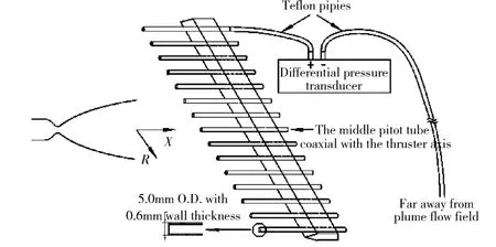
An array consisting of 15 parallel pitot tubes made of 304 stainless steel is employed to determine the pressure field of the plume. The inlets of the tubes are placed in a line with an interval of 20 mm. Each probe has an outside diameter of 5.0 mm and an inside diameter of 3.8 mm, as schematically shown in Fig. 3. The transducers attached to the tubes at symmetric positions with respect to the middle line have the same ranges of measurement with accuracy of 0.25% FS, and the ranges of the middle transducers and both sides ones are 30 kPa, 10 kPa, 5 kPa, 5 kPa, 5 kPa, 5 kPa, 1 kPa, 1 kPa, respectively. The array of pitot tubes is mounted on a traversing mechanism for making measurements at different distances from the outlet of the thruster nozzle.

Fig. 3 Schematic diagram of pitot tube array with differential pressure transducers
1.4 Test procedure
During experiments, the traversing mechanism carrying the pitot tubes array is shifting along the thruster axis direction (X) to determine the pressure distribution in the radial direction (R) at different distances from the nozzle outlet. The measuring range is from 140 mm to 600 mm in the axial direction (X), and 140 mm in the radial direction (R). The relative positions of the thruster and the pitot tube array are optically adjusted before the test to keep the pitot tube array moving along the axis of the thruster.
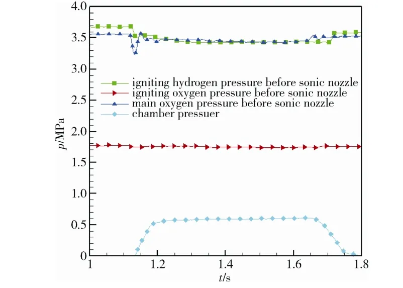
The vacuum chamber is initially pumped into a vacuum state without the nozzle exhaust to establish zero settings for the sputtered thin pressure transducer in the combustion chamber and the differential pressure transducers of the pitot tube array. The vacuum pressure as the zero point is lower than 10-4Pa, so the differential pressure read from the sensor could be taken as the actual pressure. A repeated short-time exhausting mode instead of a continuous mode is employed to maintain the dynamic vacuum with exhaust because of its large flow rate. As shown in Fig. 4, the ignition hydrogen pressure, the ignition oxygen pressure, the main oxygen pressure in front of the sonic nozzles and the chamber pressure reach steady states in about 100 ms after the main oxygen enters. Hence, the exhausting time is set as 300 ms to obtain a relatively steady plume field while maintaining the dynamic vacuum pressure. Since the hydrogen could not be absorbed by the liquid nitrogen heat sink, it would take a very long time to reduce the background pressure to the level below 10-4Pa after exhausting. As a compromise, the exhaust begins when the vacuum pressure is lower than 3.0×10⁻³Pa. The dynamic background pressure is about 3 Pa.

Fig. 4 Representative pressure curves during an exhaust
2 Numerical method
The vacuum plume covers various flow regions, including the continuum, the transition, and the free molecular flow regions. The continuum flow is found in the core area of the plume. The transition flow and the free molecular flow are in the far areas of the plume. Therefore, the vacuum plume could not be described by one mathematical model alone. For the continuum flow, the governing equations are the N-S equations, which are solved by using the traditional Computational Fluid Dynamic (CFD) method. For the free molecular flow, the governing equation is the Boltzmann equation without the collision factor. However, for the transition flow, the governing equation is the full Boltzmann equation. The most widely used method for the solutions of the Boltzmann equation is the Direct Simulation Monte Carlo (DSMC) method. In this paper, a combined CFD-DSMC method is used for the numerical analysis[21]. For the CFD-DSMC method, the physical range for the CFD analysis is extended from the inside of the nozzle out into the free space beyond the point where, because of the rapid gas expansion, the continuum theory is considered valid. A DSMC analysis is performed for the flow region far downstream of the nozzle exit where the flow can no longer be described by the continuum theory. The DSMC analysis uses the boundary condition information from the corresponding CFD analysis at a surface where the continuum theory is applicable.
In the DSMC calculation, the flow domain is first divided into a number of cells. Then the computational particles are placed into the cells. All particles carry the information of position, velocity, internal energy and weight factor. During each time step, all particles are handled in two loops. The outer loop extends over all grid cells in which all particles move and interact with the boundary surfaces; the inner loop extends over the particles within a cell in which particles collide with each other.
The DSMC-based PWS (Plume Work Station) software[22], as a general simulation software developed by Beihang University, is employed in the current investigation for the plume effect simulation. The software is modularized, which includes the initial condition module, the boundary condition module, the parameter module and the mesh generation module. With these modules, various kinds of parameters can be transformed into the format adopted by the software, and then the data and the control interface are processed. The uniform data and the control interface provide a man-machine interaction environment. Users can make further modifications and define operation processes on the interface.
3 Results and discussions
3.1 Plume field of the scaled model thruster
The measured pitot pressures are corrected by the flow angles acquired from the DSMC results to reduce the errors caused by parallel tubes. The pressure field of the plume obtained by the DSMC method is converted to the pressures behind the normal shock wave by Eq. (1), for comparisons with the experimental pitot pressures.

Fig. 5 through Fig. 7 show the pressure distributions along the radial direction (R) at 140 mm, 350 mm, and 600 mm away from the nozzle exit plane, respectively. The upper horizontal axis and the right vertical axis represent the distance normalized by the exit diameter(X / De) and the plume pressure normalized by the chamber total pressurerespectively. The DSMC computational results are found in excellent agreement with the experimental data. The pressure profiles show convex shapes (except the one at 140 mm) and complicated shock waves produced by the bell nozzle are observed. When the distance away from the nozzle exit increases, the maximum pressure at each radial line shifts away from the axis, and the pressures near the axis decrease while the pressures far from the axis increase, resulting in profiles with a tendency to flatten. From the comparisons between the experimental and numerical simulation results of the model thruster, the approach combining CFD and DSMC shows a powerful ability to predict the plume pressures.

Fig. 5 Comparison between DSMC simulation and measured pitot pressure profiles along R direction at X = 140 mm

Fig. 6 Comparison between DSMC simulation and measured pitot pressure profiles along R direction at X = 350 mm

Fig. 7 Comparison between DSMC simulation and measured pitot pressure profiles along R direction at X = 600 mm
4 Conclusions
To study the plume flow field of the second stage engines of the Chinese ‘CZ’ launch vehicle, a 60 N model thruster of hydrogen/oxygen with the same propellant, the same mixing ratio and the same shrinked bell-nozzle profile as those of the actual rocket engine is designed and tested in the Plume Effect Experimental System of Beihang University.
The pressures behind the shock wave along the radial direction at the different distances from 140 mm to 600 mm away from the nozzle exit plane in the plume field are determined by using a pitot tube array. The results show the tendency of the plume produced from a bell-nozzle expanding into the vacuum. The experimental data are compared with the numerical simulation results based on the CFD-DSMC method, and it is shown that the numerical method predicts both the tendency and the values precisely as compared with the experimental results, which demonstrates the powerful ability of the numerical approach to estimate the effects of the plume flows. The characteristics of the pressure field of the model thruster plume are obtained by the present study and can serve as a basis for the plume effect analysis of the archetype engine.
[1] Bird G A. Approach to translational equilibrium in a rigid sphere gas[J]. Physics of Fluids, 1963, 6(10): 1518-1519
[2] Bird G A. Shock-wave structure in a rigid sphere gas[C]//Proceedings of the Fourth International Symposium, Institute for Aerospace Studies. Toronto, 1965: 216
[3] Bird G A. Molecular gas dynamics[M]. Oxford: Clarendon Press, 1976: 250
[4] Baerwald R K. Rocket exhaust plume impingement on the Voyager spacecraft, AIAA 78-1090[R], 1978
[5] Guernsey C S. Effects of translational nonequilibrium on vacuum plume expansions[J]. AIAA Journal, 1982, 20(7): 885-888
[6] Pham-Van-Diep G, Erwin D, Muntz E P. Nonequilibrium molecular motion in a hypersonic shock wave[J]. Science, 1989, 245: 624-626
[7] Boyd I D, Penko P F, Carney L M. Efficient Monte Carlo simulation of rarefied flow in a small nozzle, AIAA 90-1693[R], 1990
[8] Lumpkin F E. A CFD/DSMC analysis of plumes and plume impingement during Shuttle/Mir docking[C]//30thThermophysics Conference. San Diego, 1995
[9] Kannenberg K C, Boyd I D. Three-dimensional Monte Carlo simulations of plume impingement[J]. Journal of Thermophysics and Heat Transfer, 1999, 13(2): 226-235
[10] Tseng K, Hu L, Kuo T, et al. Disturbance analysis from plume impingement by using the parallel DSMC Code (PDSC), AIAA 2007-4412[R], 2007
[11] Lengrand J, Allegre J, Raffin M. Experimental investigation of underexpanded exhaust plumes[J]. AIAA Journal, 1976, 14(5): 692-694
[12] Bailey A B. Flow-angle measurements in a rarefied nozzle plume[J]. AIAA Journal, 1987, 25(10): 1301-1304
[13] Boyd I D. Analysis of rotational nonequilibrium in standing shock waves of nitrogen[J]. AIAA Journal, 1990, 28(11): 1997-1999
[14] Boyd I D, Penko P F, Meissner D L, et al. Experimental and numerical investigations of low-density nozzle and plume flows of nitrogen[J]. AIAA Journal, 1992, 30(10): 2453-2461
[15] Boyd I D, Beattie D R, Cappelli M A. Numerical and experimental investigations of low-density supersonic jets of hydrogen[J]. Journal of Fluid Mechanics, 1994, 280: 41-67
[16] Broc A, De Benedictis S, Dilecce G, et al. Experimental and numerical investigation of an O2/NO supersonic free jet expansion[J]. Journal of Fluid Mechanics, 2004, 500: 211-237
[17] Xiao Z J, Cheng H E, Zhou W M, et al. Pressure investigations of carbon dioxide nozzle plume flow in simulated space environment, AIAA 2007-5188[R], 2007
[18] Wang W L, Cai G B, Zhou J P. Large-scale vacuum vessel design and finite element analysis[J]. Chinese Journal of Aeronautics, 2012, 25(2): 189-197
[19] Ling G L, Wang W L, Cai G B, et al. Liquid helium heat sink design for experimental study of engine's plume and vacuum effects[J]. Journal of Aerospace Power, 2011, 26(11): 2630-2635
[20] Ling G L, Cai G B, Zhang J H. Oil-free vacuum system design based on vacuum plume experiment[J]. Journal of Aerospace Power, 2013, 28(5): 1173-1179
[21] Tang Z Y, He B J, Cai G B. Investigation on a coupled Navier–Stokes–Direct Simulation Monte Carlo method for the simulation of plume flowfield of a conical nozzle[J]. International Journal for Numerical Methods in Fluids, 2014, 76(2): 95-108
[22] He B J, Zhang J H, Cai G B. Research on vacuum plume and its effects[J]. Chinese Journal of Aeronautics, 2013, 26(1): 27-36
- 航天器环境工程的其它文章
- 我国第一个卫星运载火箭总体方案的优化

