
The design of control system applied in artificial grass tufting machine adopting servomotors
2015-02-24 07:40:00KunkunANHuiliangDAIXinjiaTAN
机床与液压 2015年24期
Kun-kun AN,Hui-liang DAI,Xin-jia TAN
(College of Mechanical Engineering,Donghua University,Shanghai 201620,China)
1 Introduction
The artificial turf has a broad application prospect,and it has been widely used in all kinds of sports,fitness and leisure places such as football field,tennis court,hockey,golf course,sports complex,amusement park,kindergarten,residential courtyard,park and commercial environment[1].
The artificial grass tufting machine has a large electromechanical coupling system,and it is usually made up of the host computer,yarn feeding,needle and mobile system,the ring system,cutting system,bottom cloth feeding system.
The advanced tufting machine technologies are mainly in the hand of foreign companies such as United States Tuftcocompany,the CMC company,British Cobble company,Japan Yamaguchi Industrial Co.Ltd[2-3]and each of these brands have strengths and weaknesses.At present,although there are many companiesengaged in the production of artificial turf in China,they don’t have the core technologies,most of the equipments are imported and the price is very expensive.Due to the weak foundation,less investment and no keytechnologies,the development of artificial grass tufting machine in China is not good.With the development of machinery manufacturing technologies,many companies are able to make some small mechanical parts of the machine,but the design of the control system becomes a problem.The independent research and development of the control system are in demand[4].
2 System overall design
According to the analysis of the artificial grass tufting machine,it adopts servo motors to drive four rollers and achieve the control of the yarn feeding and the spindle is driven by the induction motor.
2.1 Design of main control system
The main control system consists of a touch screen,LMC20,variable-frequency drive,man-machine interface and a variety of peripheral devices.Console is mountedbeside the machine and it could centrally monitor and control the system,as shown in Fig.1.
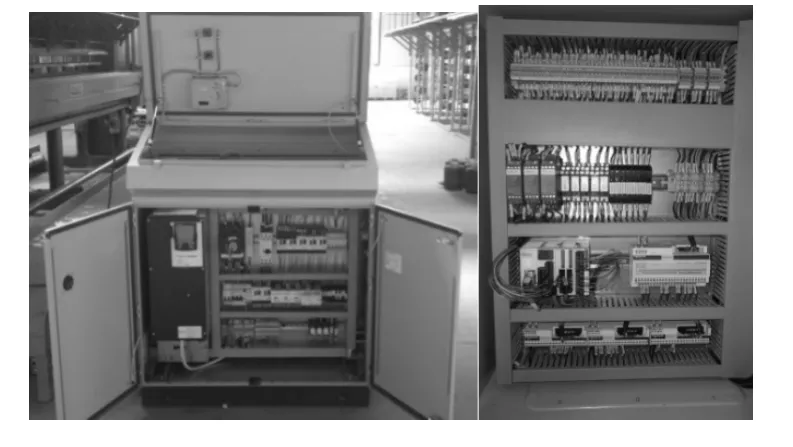
Fig.1 Electrical control cabinet
In this control system,the touch screen as the master station displays and signals,the slave station is made upof LMC20,ATV71 and detection module.Through the CANopen bus,the communication between LMC20,ATV71 and servo drivecould be achieved.The overall design diagram is shown in Fig.2.
Master station touch screen achieves the following functions:selection of operating mode,the inputof feeding roller speed,spindle speed input,the bottom fabric roller speed input,start and stop,alarm display and data record.Slave station LMC20 receives the data signal and the processeddata will be transmitted to ATV71,servo drives and detection module control the spindle induction motors,servo motors,and change the actual yarn feeding volume and turf densityvia the CANopen bus.When the position of the needle plate is changed,grass height will be changed.Detection module can selectively monitor the motor operation state with the feedback of the current process parameters and this could ensure the safe and efficient operation of the machine.
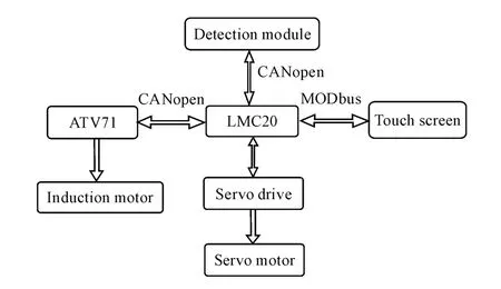
Fig.2 The overall block diagram of the control system
Roller control servo motors,bottom fabric servo motors,etc,as the CANopen nodes,are synchronized with the spindle motor through the synchronizationnode.System bus network layout is shown in Fig.3.

Fig.3 System bus layout
2.2 Design of field control system
The field control system consists of the detection module,the servo motors,the servo motor drives,monitoring devices,the security module,the hydraulic pump and other components.Besides the servo motors,there are two induction motors driving the spindle in the whole system,and the exterior encoder is adopted to obtain the induction motor speed information and monitor them.Servo motors use its photoelectric encoder to get speed information.Pressure sensors and alarm signals will be feedback to the detection module to get respond.Each of these modules are connected to the CANopen bus as a node.
3 The security module
Schneider’s security module provides us with a very good security solution.It has many unique elements:① the module is compact,small installing space,but there are three security output channels;②security module with terminals for disassembly,easy to machine maintenance;③in order to facilitate the operation personnel to diagnose,the front panel of the mod-ule with three light emitting diodes can display the monitoring circuit state information;④monitoring the function of the start button can be achieved by wiring[5].
The system selects the security module Schneider XPSATE and XPSAFL series.It monitors the emergency stop circuit compliance with EN/ISO13850 and EN 60204-1 standard and monitors the switch protection devices compliance with EN1088/ISO14119 standard.Some of security module wiring diagram is shown in Fig.4.

Fig.4 Security module XPSAFL wiring diagram
Security module XPSATE can effectively monitor emergency stop and start switch,limit switch,light switch.Magnetic switch monitorsthe door of main mechanical driving part,the light switch is used to monitor whether there is any object in the danger area during the production.In addition to the above safety devices,it needs a special safety device,which is emergency stop pull rope switch.It is very important for the operational area and the machinery to be dangerous.It is very important to the dangerous operational area and the machine[6].
4 Design ofthe touch screen and LMC20 controller
Master station touch screen HMIGX03502 has two interfaces COM1 and COM2,respectively,RS 232 communication port and RS 422/RS 485 communication port,by using RS485 of COM2 connect with RS485 RJ45 port of LMC20.Specific wiring diagram is shown in Fig.5.
Programthe touch screen by Schneider man-machine interface configuration software tool Vijeo-Designer.Part of the interface is shown in Fig.6.
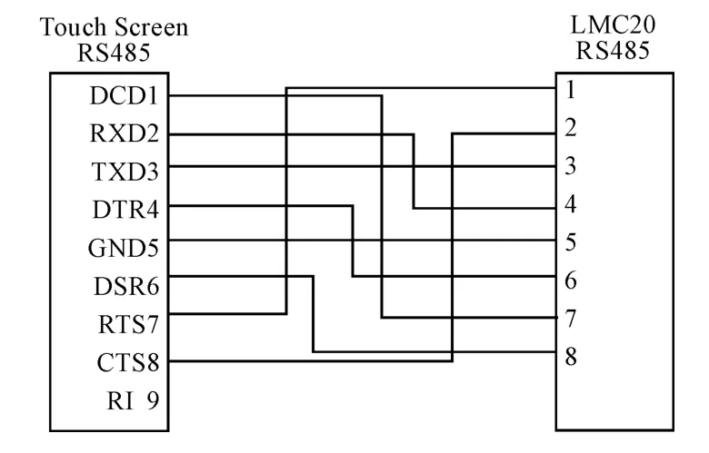
Fig.5 Serial port wiring diagram

Fig.6 User interface
LMC20 achieves the control of system and communication with the touch screen.Its resources are assigned as follows:SUB-D interface for connection with spindle encoder to measure and monitor the main shaft;RJ45 for communication with touch screen;HE10 interface to connect a variety of power inputs,relay inputs and outputs;CANopen interface for communication with VFD,detection module and other modules;status LED can monitor the state of each interface.Software design of the system mainly consists of two parts:soft PLC transplantation,bus configuration and program design.LMC20 is programmed by CoDeSys with hybrid programming approach.When touchscreen signals to LMC20 in order,the signals will be processed in Sequential Function Chart(SFC).
4.1 Communication between LMC20 and Servo motor drives
First,the servo drives are set to position mode driven by message,and touch screen inputs the appropriate speed.The information input is transferred to LMC20 via communication port.After the operation,LMC20 sends messages and connects to the CANopen communication port of servo controller.Servo controller receives signals,after internal calculation,drives the servo motors to reach the appropriate speed.The encoders will feedback to the servo controller,and a closed loop system is done,stable operation is achieved.Meanwhile,spindle encoder detects spindle speed and the position of needle,feedbacks to LMC20 and compare to achieve synchronization between servo motors and spindle motors.
4.2 Communication between LMC20 and ATV71
ATV71 communication port is Modbus network port,LMC20 CANopen communication port is the Sub-D connectors.So CANopen adapter must be used to achieve the communication between ATV71 and LMC20,it is shown in Fig.7.
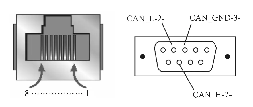
Fig.7 CANopen interface adapter conversion
5 Fault detections
The monitoring system includes the following modules:system parameters online reading module,CAN-open bus data communication module,online data analysis module and fault diagnosis module.After the initialization,the monitoring system will be connected to the CANopen bus,get identified by IPC node via message code,download the online system parameters from the node and get grass height and motor speed ratio.The various parameters are displayed on the monitoring system interface,after information processing,the motor which needs to monitor will be selected out.The signals of motor status could be divided into two categories:one for normal motor status signals whose volatility is beyond the permitted range,and the other for the motor status signals whichwill notbe changedregularly.For the first abnormal signal,the motor fault diagnosis and treatment will beokay.The second abnormal signalsbecome more complicated,first to diagnostic communication fault,and then determine whether there is a problem with communication.If there is no problem with communication,it must carry onthe fault diagnosis of the control circuit to determine whether the control circuit is okay.If there is still no problemwith control circuit,then it will determine whether the motors fail.
6 Conclusions
According to the analysis of artificial grass tufting machine adopting servomotors,this paper presented a general control system based on CANopen bus.The master station is Schneider touchscreen,the slavestation is Schneider motion controller LMC20.Using servo motors in Roller control system to achieve the speed conversion,the system becomes more stable,flexible,and easy to expand and it isgoodforthe later redevelopment.
[1]Connelly T,Teubert C.Airsideapplicationsforartificial turf[R].U.S.Department of Transportation,Federal Aviation Administration,2006:1.
[2]Liu Huansheng.Development status of tufted carpet technology[J].Beijing Textile Journal,2002,23(3):7-11.
[3]Liu Qi.Development and prospect of artificial turf[J].Technology-oriented,2012,14:411.
[4]Yao Yiwen,Song Guilong,The present situation and development of artificial turf[J].Chinese Educational Technology and Equipment,2007(7):52-53.
[5]Schneider security automation solutions[Z].2008:29-32.
[6]Schneider security detection solutions[Z].2008:158-167.
- 机床与液压的其它文章
- 汽车磁流变阻尼器多目标优化分析
- 《机床与液压》2015年目次索引
- Introduction of the Fluid Control Engineering Institute of Kunming University of Science and Technology
- Overload intelligent detection method of lift platform’s number of people under auxiliary visual
- Impact of fluid properties on the injection process in a common-rail direct injection system
- Pouring characteristics analysis on the concrete pump truck boom based on rigid-flexible coupling method