
Residual Phase Noise and Time Jitters of Single-Chip Digital Frequency Dividers
2015-02-13 01:57:20LuLuYanSenMengWenYuZhaoWenGeGuoHaiFengJiangandShouGangZhang
Lu-Lu Yan, Sen Meng, Wen-Yu Zhao, Wen-Ge Guo, Hai-Feng Jiang, and Shou-Gang Zhang
Residual Phase Noise and Time Jitters of Single-Chip Digital Frequency Dividers
Lu-Lu Yan, Sen Meng, Wen-Yu Zhao, Wen-Ge Guo, Hai-Feng Jiang, and Shou-Gang Zhang
—In this paper, we demonstrate the residual phase noise of a few microwave frequency dividers which usually limit the performance of frequency synthesizers. In order to compare these dividers under different operation frequencies, we calculate additional time jitters of these dividers by using the measured phase noise. The time jitters are various from ~0.1 fs to 43 fs in a bandwidth from 1 Hz to 100 Hz in dependent of models and operation frequencies. The HMC series frequency dividers exhibit outstanding performance for high operation frequencies, and the time jitters can be sub-fs. The time jitters of SP8401, MC10EP139, and MC100LVEL34 are comparable or even below that of HMC series for low operation frequencies.
Index Terms—Frequency divider, phase noise, spectra analysis, time jitter.
1. Introduction
Frequency synthesizers are widely used in modern electronic systems and their near carrier offset phase noise is often critical to many applications. Most synthesizers are of the phase-locked type, employing frequency multipliers or frequency dividers to convert frequencies[1],[2]. Usually, noise introduced by passive components is negligible, and frequency multipliers or frequency dividers limit the performance of these synthesizers. In comparison with frequency multipliers, frequency dividers are more flexible to use with plenty of chooses. A hybrid frequency divider, composed of a digital divider and a regenerative divider, converts an 8 GHz signal to 5 MHz with time jitters about 6 fs in a bandwidth of 1 Hz to 100 Hz and about 40 fs in a bandwidth of 1 Hz to 100 kHz[3]. This result is comparable with the best frequency multiplier named nonlinear transmission line (NLTL)[4],[5]which is not commercially available any more.
The regenerative frequency divider exhibits the lowest additional phase noise for low frequency operation, the additional jitter (160 MHz to 5 MHz) in the bandwidth from 1 Hz to 100 Hz is about 5 fs[3]. However, the regenerative frequency divider is bulky and expensive. Digital logic units, such as complex programmable logic device (CPLD) and field programmable gate array (FPGA), can easily realize programmable frequency-dividing. However, the additional noise of CPLD and FPGA is high[6]. In order to have a simple and compact low-noise synthesizer, the single-chip digital frequency divider seems to be the best solution. Unfortunately, manufactures of these chips do not provide the near carrier additional phase noise of their products.
In this paper, we show the residual phase noise and additional time jitters of six models of digital frequency dividers made by three companies (Onsemi, Zarlink, and Hittite). At low frequencies, the residual phase noise follows 1/f rules in general, where f is frequency. The time jitters are given for comparing additional noise level induced by these frequency dividers in different frequencies.
2. Experimental Setup and Measurement Results
Fig. 1 shows the experimental setup. We drive two identical digital frequency dividers under test (DUT) with a common reference source. RF/MW amplifiers are used to produce about 10 dBm to 19 dBm frequency-divided signals. After DUT, a low-pass filter is used to pick up the necessary signals. The phase detector is a 7 dBm level mixer which gives the phase difference variation. A phase shifter is employed to establish the quadrature phase (90°) between two DUT signals at the mixer inputs. The signal out from the mixer IF port is transmitted to a dynamicsignal analyzer, also called fast Fourier transmitter (FFT), via a low-pass filter and low noise baseband amplifier. In this measurement system, the mixer and amplifier convert a phase fluctuation to a voltage change with a conversion factor of about 9.7 V/rad.
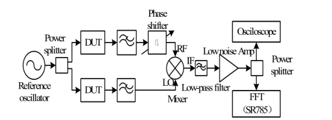
Fig. 1. Phase noise measurement experimental setup, DUT: Digital-frequency-divider under test.
We choose six digital frequency dividers, including SP 8401, MC10EP139[7], MC100LVEL34[8], HMC361[9], HMC362[10], and HMC363[11]. Although the datasheets of these dividers often claim only the maximum operation frequency, these dividers do not work normally when the input frequency below a certain threshold. SP8401 operates only in relative low frequencies ranging from 50 MHz to 300 MHz; MC10EP139 and MC100LVEL34 can work up to 1 GHz; HMC series dividers run well over 10 GHz. We design a PCB layout by putting these discrete components in a large space for avoiding stray effects.
Fig. 2 to Fig. 7 show the residual double sideband phase noise of corresponding frequency dividers. These data have been reduced 3 dB from the FFT measured data to represent the noise of a single divider. In this experiment, the input operating frequencies are listed in the Table 1. The output power of the common reference source is 3 dBm. We add attenuators behind the low-pass filter, in order to ensure that the input power at the mixer’s LO port is about 8 dBm and -1 dBm at the RF port.
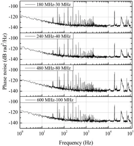
Fig. 2. Residual double-sideband (DSB) phase noise of the MC10EP139 with different operation frequencies.
Note that the measured phase noise also includes noise induced by the RF/MW amplifiers and measurement system. Especially at low operation frequencies, the measurement noise is not negligible. Noise spurs shown in these figures are attributed to the power supply.

Fig. 3. Residual DSB phase noise of the MC100LVEL34.
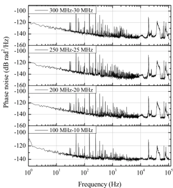
Fig. 4. Residual DSB phase noise of the SP8401.
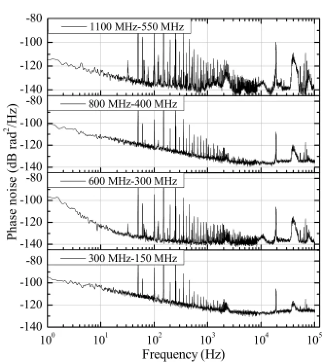
Fig. 5. Residual DSB phase noise of the HMC361.
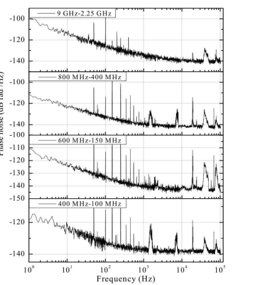
Fig. 6. Residual DSB phase noise of the HMC362.
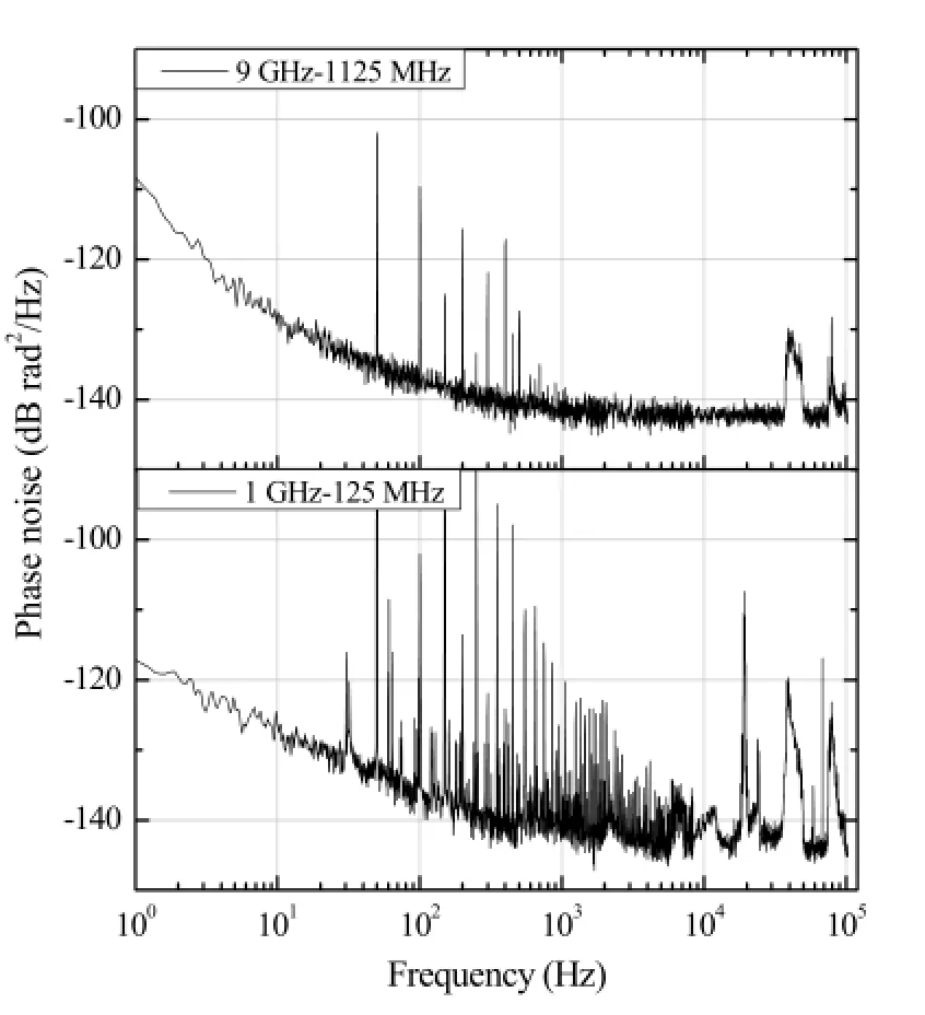
Fig. 7. Residual DSB phase noise of the HMC363.
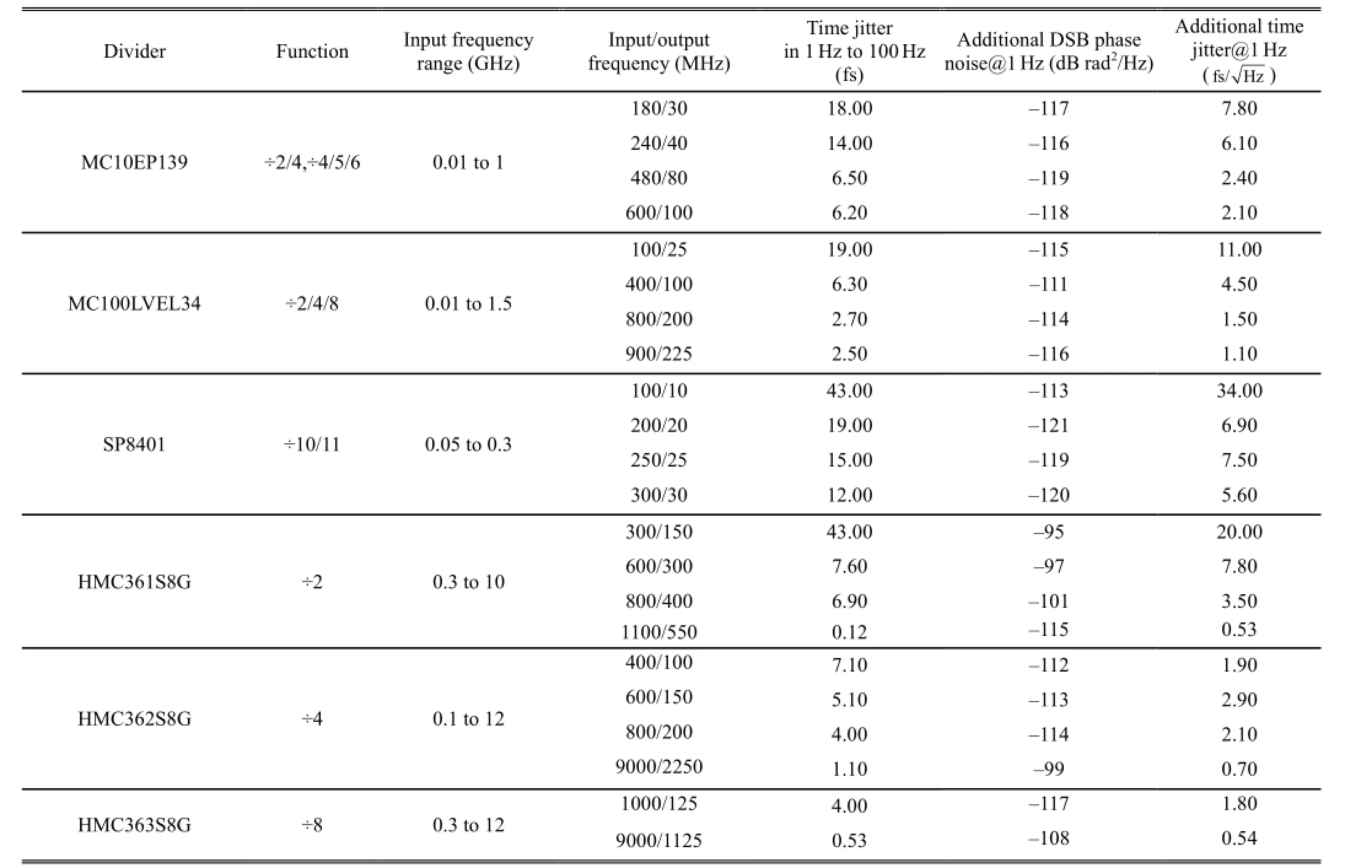
Table 1: Measured phase noise and calculated time jitters (Note that noise introduced by RF/MW amplifiers and measurement system is included.)
It is not easy to compare these curves directly because the frequencies are different. We calculate the time jitters as shown in Table 1 without considering the noise spurs[12], so as to give a quick comparison of these dividers. The computational formula is given by
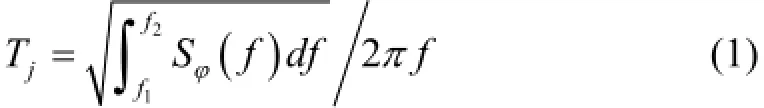
where Tjis the time jitter, f2and f1are the up and downlimit, respectively. Sϕ(f ) is the phase noise power spectra density, and f is the output frequency of the dividers under test. The operation frequency range is obtained by a quick test. We tune the input frequency and monitor the output of these dividers. When the input frequency is below a certain value (lower operation frequency), the output of these dividers becomes very noisy. The lower operation frequencies may change the dependence on the surrounding circuits. However, it has never been close to DC as indicated in these datasheets.
SP8401 made by Zarlink is an old produce with a CMOS and TTL compatible level. MC10EP139 and MC100LV EL34 made by Onsemi have an emitter coupled logic (ECL) input/output level. The wafer process of these two dividers is MOSAIC5 of Onsemi. MOSAIC5 is a trench isolated, double epi, double poly, and multi-layer metal, it has a minimum photolithography feature size of 0.7 μm. Additionally, MOSAIC5 utilizes an industry standard inorganic interlayer dielectric layer. HMC series frequency dividers made by Hittite employes the GaAs HBT-A wafer process. The InGaP GaAs HBT has an ultra-fast response, and the operation frequencies of these HBTs can be up to 60 GHz.
3. Conclusions
In this work, we have measured the phase noise and time jitters of six digital frequency dividers. Generally, the time jitter is lower while the operation frequency is higher, and a high speed digital frequency divider exhibits lower additional time jitter. HMC series frequency dividers, with InGaP GaAs heterojunction bipolar transistors (HBT) technology, exhibit outstanding performance for high operation frequencies; the time jitter can be sub-fs. The time jitter in a bandwidth of 1 Hz to 100 Hz is in the range of 0.1 fs to 43 fs dependent on the operation frequency and divider model. In comparison with dividers realized with the CPLD or FPGA, single-chip digital frequency dividers have lower additional noise.
[1] A. Hajimiri and T. H. Lee, “A general theory of phase noise in electrical oscillators,” IEEE Journal of Solid-State Circuits, vol. 33, no. 2, pp. 179-194, 1998.
[2] S. Shekhar, D. Gangopadhyay, E. C. Woo, and D. J. Allstot,“A 2.4-GHz extended-range type-I sigma-delta fractional-N synthesizer with 1.8-MHz loop bandwidth and -100-dBc/Hz phase noise,” IEEE Trans. on Circuits and Systems Ⅱ: Express Briefs, vol. 58, no. 8, pp. 472-476, 2011.
[3] A. Hati, C. W. Nelson, C. Barnes, D. Lirette, T. Fortier, et al., “State-of-the-art RF signal generation from optical frequency division,” IEEE Trans. on Ultrasonics Ferroelectrics and Frequency Control, vol. 60, no. 9, pp. 1796-1803, 2013.
[4] R. Boudot, S. Guérandel, and E. de Clercq, “Simple-design low-noise NLTL-based frequency synthesizers for a CPT Cs clock,” IEEE Trans. on Instrumentation and Measurement, vol. 58, no. 10, pp. 3659-3665, 2009.
[5] M. J. W. Rodwell, M. Kamegawa, Y. M. Case, et al., “GaAs nonlinear transmission-lines for picosecond pulse generation and millimeter-wave sampling,” IEEE Trans. on Microwave Theory and Techniques, vol. 39, vol. 7, pp. 1194-1204, 1991.
[6] C. E. Calosso and E. Rubiola, “Phase noise and jitter in digital electronic components,” in Proc. of 2014 IEEE Intl. Frequency Control Symposium, 2014, pp. 532-534.
[7] ON Semiconductor. (April 2012). 3.3V/5V ECL ÷2/4,÷4/5/6 clock generation chip. [Online]. Available: http://www.onsemi.cn/pub_link/Collateral/MC10EP139-D. PDF
[8] ON Semiconductor. (September 2012). 3.3V ECL ÷2, ÷4, ÷8 clock generation chip. [Online]. Available: http://www.onsemi.cn/pub_link/Collateral/MC100LVEL34-D.PDF
[9] Hittite Microwave Corporation. (May 2013). SMT GaAs HBT MMIC DIVIDE-BY-2, DC-10 GHz. [Online]. Available: http://www.hittite.com/content/documents/data_ sheet/hmc361s8g.pdf
[10] Hittite Microwave Corporation. (May 2013). SMT GaAs HBT MMIC DIVIDE-BY-4, DC-12 GHz. [Online]. Available: http://www.hittite.com/content/documents/data_ sheet/hmc362s8g.pdf
[11] Hittite Microwave Corporation. (May 2013). SMT GaAs HBT MMIC DIVIDE-BY-8, DC-12 GHz. [Online]. Available: http://www.hittite.com/content/documents/data_ sheet/hmc363s8g.pdf
[12] A. Hajimiri, S. Limotyrakis, and T. H. Lee, “Jitter and phase noise in ring oscillators,” IEEE Journal of Solid-State Circuits, vol. 34, no. 6, pp. 790-804, 1999.

Lu-Lu Yanwas born in Shaanxi Province, China in 1989. She received the B.S. degree in electrical engineering from Shaanxi University of Technology (SNUT), Hanzhong in 2011 and the M.S. degree in electrical engineering from Shaanxi University of Science and Technology (SUST), Xi’an in 2014, respectively. Now, she is an engineer at National Time Service Center (NTSC). Her research interests include ratio frequency signal processing, microwave signal processing, and optical frequency comb.

Sen Mengwas born in Jiangsu Province, China in 1989. He received the B.S. degree from Xi’an Shiyou University (XASU), Xi’an in 2012. He is currently pursuing the M.S. degree with XASU. His research interests include ratio frequency and microwave signal processing.

Wen-Yu Zhaowas born in Shanxi Province, China in 1982. He received the B.S. degree electrical engineering from the Chang’an University, Xi’an in 2004 and the M.S. degree in electrical engineering from University of Chinese Academy of Sciences (UCAS), Beijing in 2008, respectively. He is currently pursuing the Ph.D. degree with the Department of National Time Service Center, Chinese Academy of Sciences (CAS). His research interests include the technology of test and measurement using in the time and frequency equipments.
Wen-Ge Guowas born in Shaanxi Province, China in 1967. He received the B.S. degree from Northwestern University Xi’an, Shaanxi in 1988, the M.S. degree from Xi’an Institute of Precision Optics and Mechanics of CAS, in 1994, and his Ph.D degree from Dresden Technical University, Germany in 2003. Now he is a professor with the School of Science, XASU. His current research interests include the technology of optoelectronics and organic optoelectronics.

Hai-Feng Jiangwas born in Heilongjiang Province, China in 1973. He recieced the B.S. degree from Harbin University of Science and Technology, Harbin in 1995 and the M.S. degree from UCAS, Beijing in 2003, and his Ph.D degree from Paris University 13, Paris in 2010, respectively. Now he is a professor at NTSC.
Prof. Jiang has been working on time and frequency metrology for more than ten years at Shanghai Institute of Optics and Fine Mechanics from 2003 to 2005, l’Observatoire de Paris-Systèmes de Référence Temps-Espace in France from 2007 to 2010, National Institute of Standards and Technology in USA from 2011 to 2013, and NTSC from 2005 to 2007 and since 2013. His research interests include ultra-low phase noise synthesizer, ultra-stable microwave generation, ultra-stable laser, frequency transition, and optical frequency comb.
Shou-Gang Zhangwas born in Shaanxi Province, China in 1966. He received the B.S. degree from Northwestern University Xi’an, Shaanxi in 1990, the M.S. degree from NTSC of CAS in 1993, and his Ph.D degree from Université Pierre et Marie Curie, France in 2004. Now he is a professor at NTSC. His research interests include atomic clock and time & frequency measurement and transfer.
Manuscript received November 5, 2014; revised December 18, 2014. This work was supported by the National Natural Science Foundation of China under Grant No. 91336101 and No. 61127901, and the West Light Foundation of the Chinese Academy of Sciences under Grant No. 2013ZD02.
L.-L. Yan, W.-Y. Zhao, and S.-G. Zhang are with the Key Laboratory of Time and Frequency Standards, National Time Service Center (NTSC), Chinese Academy of Sciences, Xi’an 710600, China (e-mail:yanlulu@ntsc.ac.cn; zhaowy@ntsc.ac.cn; szhang@ntsc.ac.cn).
Hai-Feng Jiang is with the Key Laboratory of Time and Frequency Standards, National Time Service Center, Chinese Academy of Sciences, Xi’an 710600, China (Corresponding author e-mail: haifeng.jiang@ntsc.ac.cn).
S. Meng and W.-G. Guo are with the School of Science, Xi’an Shiyou University, Xi’an 710065, China (e-mail: 705236315@qq.com; wengeguo@126.com).
Digital Object Identifier: 10.11989/JEST.1674-862X.411051
 Journal of Electronic Science and Technology2015年3期
- Journal of Electronic Science and Technology的其它文章
- Energy Management Strategies for Modern Electric Vehicles Using MATLAB/Simulink
- Hybrid Aging Delay Model Considering the PBTI and TDDB
- Time-Efficient Identification Method for Aging Critical Gates Considering Topological Connection
- A Methodology to Measure the Environmental Impact of ICT Operating Systems across Different Device Platforms
- Enhancement of Distributed Generation by Using Custom Power Device
- Influence of Taxation on Supply and Demand in Tomorrow’s Crowd Energy Paradigm