
A Highly Stable Electrochemical Scanning Tunneling Microscope
2015-01-13 02:25:42ZhigngXiJihoWngYubinHouQingyouLu
Zhigng XiJiho WngYubin HouQingyou Lu
a.High Magnetic Field Laboratory,Chinese Academy of Sciences and University of Science and Technology of China,Hefei 230026,China
b.Hefei National Laboratory for Physical Sciences at the Microscale,University of Science and Technology of China,Hefei 230026,China
A Highly Stable Electrochemical Scanning Tunneling Microscope
Zhigang Xiaa,b,Jihao Wanga,b,Yubin Houa,Qingyou Lua,b∗
a.High Magnetic Field Laboratory,Chinese Academy of Sciences and University of Science and Technology of China,Hefei 230026,China
b.Hefei National Laboratory for Physical Sciences at the Microscale,University of Science and Technology of China,Hefei 230026,China
We demonstrate a home-built electrochemical scanning tunneling microscope(ECSTM).The ECSTM exhibits highly stable performance.The drifting rates inXYandZdirections of the ECSTM are about 67 and 55.6 pm/min,respectively.Moreover,a specially designed scanner unit successfully solves the well-known problem of large leakage current in high humidity atmosphere.The mechanical structure of the ECSTM is described in detail.The excellent performances of the system are demonstrated by the measured STM images(in copper sulfate solution),including clean and well-ordered large area morphology of Au(111) and the atomically resolved image of highly oriented pyrolytic graphite.
Scanning tunneling microscope,Electrochemistry,Highly stable
I.INTRODUCTION
Since scanning tunneling microscopy(STM)was invented in the early 1980s[1],it has been presented to be a powerful technique for real space imaging of surface structures at the atomic scale.Excitingly,STM has been brought to be operated not only in ultra-high vacuum(UHV),but also in air and liquids[2−5].However,the stability of STM is still a key problem even after such a long time development.
In the normal STM,the imaging piezoelectric scanner or the sample is directly fxed on the coarse approach motor rigidly[6].The instability of the motor caused by its own and external disturbance will be transferred into the tunneling junction.Consequently,these will downgrade the stability of the STM,especially for the electrochemical STM,which needs to be equipped with a cell.Hence,the electrochemical scanning tunneling microscope(ECSTM)cannot be built as compact as a normal STM.So the mechanical drift of the ECSTM is larger than that of the normal STM.The instability of the ECSTM would not only afect the measurement of spectroscopy inZdirection,but also afect the time of measurement on a specifc target and distort the imaged lattice structure in highly resolved imaging[7].
Besides,during the measurement of ECSTM,the evaporation of the solution will change the concentration of the solution.And the external contamination would gradually difuse into the solution,resulting in the sample being polluted.These will lead to the experiment termination.However,if the ECSTM was protected in a sealed container,the evaporation of the solution would increase humidity of the container,resulting in the reduction of the insulation resistance between the tip and scanner electrode[8].As a result,a variation of the scan voltages produced a proportional leakage current,which would seriously afect the quality of the imaging.How to solve this contradiction is a big challenge.
In this work,we present how we address these issues by adopting a stack piezoelectric motor to drive a detachable scanner unit for the coarse approach.The specially designed scanner unit successfully solves the well-known problem of large leakage current in high humidity atmosphere.The excellent performances of the ECSTM are demonstrated by the measured images∶(i)clean and well-ordered large area morphology of Au(111)and(ii)the atomically resolved image of highly oriented pyrolytic graphite(HOPG)in spiral scan mode[9],which was the frst spiral scan image in electrochemical environment.
II.STM DESIGN AND WORKING PRINCIPLE
Figure 1(a)is the schematic diagram of the ECSTM. The coarse approach motor(M)of the ECSTM is a piezoelectric stack motor.The structure of the motor will be described in detail in our later work.Its work principle is similar to that of the GeckoDrive[10].However,the output force of the motor can reach~8 times that of the GeckoDrive.So it can carry more load.
The titanium frame(B)was machined by a piece of titanium plate.The scanner unit(Fig.1(c))was installed underneath the stack motor.The scanner(S)was a
Underneath the scanner unit was a quite large space (Fig.1(a)),in which the cell(F)was mounted.After the motor was sealed by a stainless steel sleeve(A), the ECSTM was installed into a trousers-like stainless steel circuit box(G).All the wires connected to the controller through its two legs.This would guarantee the scanner,motor and wires sealing,which could avoid the leakage current problem caused by high humidity above the solution.
The scanning part can be pushed(through the sapphire ball(D))to implement the coarse approach by the stack motor.When the tested tunneling current reached the pre-set value,the coarse approach was fnished.Then the motor can withdraw a proper distance from the scanning part,which prevented the instability of the motor due to thermal drift,external vibration,etc.,from being transferred into the scanning part,resulting in a highly stable scanning part owing to its small size and excellent clamping structure.The scanning part can be withdrawn through a segment of soft rope between the scanning part and the motor.The sample stage was fxed on the steps of the frame via a string strip underneath.This minimized the mechanic loop of tunneling junction.
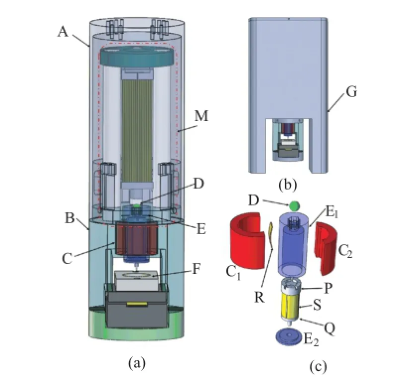
FIG.1(a)Schematic diagram of the ECSTM.(b)Assembled views of the ECSTM in circuit box.(c)Exploded views of scanner unit.Coarse A:stainless steel sleeves,B:titanium frame,C1:titanium rail cover,C2:tungsten rail,D:sapphire ball,E1:sapphire tube,E2:sapphire gap,F:cell,G:circuit box,M:approach motor,P:base,Q:sapphire tip holder,R:spring strip,S:scanner.

FIG.2 Repeated scans of the same 300 nm×300 nm Au(111)area in the solution of 50 mmol H2SO4+1 mmol CuSO4with a 60 min time interval.(a)0 min,(b)60 min, and(c)120 min.
III.PERFORMANCE
In order to check how this ECSTM performs,we took a series of experiments.All the electrolyte used in this work was 50 mmol/L H2SO4(from Merck,Suprapur grade)plus 1 mmol/L CuSO4,which were prepared using milli-Q water.All the tips were hand cut from 0.25 mm thick 80∶20 Pt/Ir wires,which were coated with polymethylstyrene.Platinum and copper wires of 0.5 mm thick were used as the counter electrode and quasi-reference electrode,respectively.
The analysis of drift in theXYplane was carried out by the collection of sequential images in the same area. The working electrode was Au(111)of bead type,prepared by the Clavilier method[16].Figure 2 shows large area constant current scans of 300 nm×300 nm taken at a 60 min interval.It is noted that the marked feature A are hardly drifted,showing very high stability.The quantitatively measuredXYplane drifting values as a function of time are plotted with linear fttings in Fig.3, where each data point is the drifting distance of A in Fig.2 and the time interval between two adjacent measurements is 15 min.In all cases,the scan rate was 1.5 lines per second,the tunneling current was 3 nA,the bias voltage was exclusively 0.084 V(tip positive)and the working electrode potential was 0.45 V(reference to Cu/Cu2+).The curves in Fig.3 show that the averageXYplane drifting rates are 67 pm/min,which are extremely low compared with that of the recently reportedECSTM[7].Measurement of drift in theZ-direction was quantifed through long-term acquisition of theZ-signal in the tunneling condition.Figure 3 provides an example of the measured drift in the electrochemical environment and reveals a rate of 55.6 pm/min.
Figure 4(a)compares the efect of atmospheric humidity on leakage current for a common and our homebuilt ECSTM.During the process of measurement,the common and our home-built ECSTM were protected in a sealed container.The humidity of the container nearly reached saturation with the evaporation of the solution.Black and blue curves exhibit the relationship between the scanning voltage and leakage current of the common and the home-built ECSTM in the high humidity atmosphere,respectively.For comparison,the red and green curves show the relationship between the scanning voltage and leakage current of the common and the home-built ECSTM in the dry atmosphere.It can be seen that in the high humidity atmosphere the leakage current of the home-built ECSTM is one order lower than that of the common ECSTM at the same scanning voltage(using 200 MΩ feedback resistance). The efect of such lower leakage current of the homebuilt ECSTM on the imaging can be ignored.So the specially designed scanner unit successfully solved the problem of large leakage current in high humidity atmosphere[8].As the fnal test,high-resolution image of HOPG sample(as shown in Fig.4(b))was obtained in spiral scan mode which can reveal the details of the drifting[9].It was the frst spiral scan image of ECSTM.The fgure was scanned at 250 s/image in constant height mode.The scan size was 7.5 nm×7.5 nm. The tip potential was at 204 mV and the working electrode was at 120 mV(reference to Cu/Cu2+).
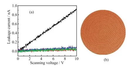
FIG.4(a)Comparison of the efect of atmospheric humidity on leakage current for the common(black and red curves show results in high humidity and dry atmosphere, respectively)and our special scanner unit(blue and green curves show results in high humidity and dry atmosphere, respectively).(b)High resolution image of HOPG sample in 0.05 mol/L H2SO4+1 mmol/L CuSO4.Scan parameters:scan size=7.5 nm×7.5 nm,scan rate=250 s/image, tip potential=204 mV and sample potential=120 mVvs. Cu/Cu2+.
IV.CONCLUSION
We present a home-built ECSTM with high stability.TheXYplane andZdirection drifting rates are about 67 and 55.6 pm/min,respectively.A specially designed scanner unit could guarantee the high stability and greatly reduce the leakage by preventing the scanner and electrode wires exposed to the high humidity above the electrolyte.The excellent performances of the system are demonstrated by the measured ECSTM images of large area morphology of Au(111)and the atomically resolved image of HOPG,which is the frst spiral scan image in electrochemical environment.
V.ACKNOWLEDGMENTS
This work was supported by the Project of Chinese National High Magnetic Field Facilities,the Fundamental Research Funds for the Central Universities (No.WK2340000035),and the National Natural Science Foundation of China(No.U1232210,No.11204306,and No.11374278).
[1]G.Binnig,H.Rohrer,C.Gerber,and E.Weibel,Phys. Rev.Lett.50,120(1983).
[2]R.Sonnenfeld and P.K.Hansma,Science232,211 (1986).
[3]K.Itaya and E.Tomita,Surf.Sci.201,L507(1988).
[4]O.Lev,F.R.Fan,and A.J.Bard,J.Electrochem.Soc.135,783(1988).
[5]J.Wiechers,T.Twomey,and D.M.Kolb,J.Electroanal.Chem.248,451(1988).
[6]Q.Wang,Y.Hou,and Q.Lu,Rev.Sci.Instrum.84, 113703(2013).
[7]A.Z.Stieg,H.I.Rasool,and J.K.Gimzewski,Rev. Sci.Instrum.79,103701(2008)
[8]M.Wilms,M.Kruft,G.Bermes,and K.Wandelt,Rev. Sci.Instrum.70,9(1999).
[9]J.Wang,J.Wang,Y.Hou,and Q.Lu,Rev.Sci.Instrum.81,073705(2010).
[10]Q.Wang,Y.Hou,and Q.Lu,Rev.Sci.Instrum.84, 056106(2013).
10.1063/1674-0068/28/cjcp1410174four-quadrant piezo tube with 4.35 mm outer diameter,8.5 mm length and 0.5 mm wall thickness(EBL #3 material from Staveley).The scanner was fxed on a base(P)and then they were glued inside of a polished sapphire tube(E1)of 15.5 mm in length×7.5 mm OD×0.75 mm.There were fve side wall slots of the base(P)to accommodate electrode wires of the scanner.The tunnel current wire went from the hole in the center of the base(P).The sapphire tip holder(Q)was glued on the free end of the scanner.A small stainless steel tube with 0.55 mm outer diameter and 0.28 mm inner diameter was mounted at the center of the tip holder,into which the tip was inserted.A sapphire gap(E2)with a properly sized hole in the center was fxed on E1by epoxy resin.The top of the sapphire tube(E1)was capped with a 3.0 mm diameter polished sapphire ball.Scanner electrode wires and tunneling current wire were elicited from the six side wall slots on the top of the sapphire tube(E1).The sapphire tube was then sandwiched by a tungsten rail(C2)and a titanium rail cover(C1),in which the sapphire tube was pressed against the knife edges of the rail by a spring strip(R)between the sapphire tube and the rail cover.
∗Author to whom correspondence should be addressed.E-mail:qxl@ustc.edu.cn,Tel.:+86-551-63600247
(Dated:Received on October 9,2014;Accepted on October 23,2014)
 CHINESE JOURNAL OF CHEMICAL PHYSICS2015年1期
- CHINESE JOURNAL OF CHEMICAL PHYSICS的其它文章
- Nanosecond Rapid Crystallization of Water Induced by Quartz Glass under Dynamic Compression
- Benzene and Toluene Levels Measured with DOAS During Vehicular Restrictions in Beijing
- Antimicrobial Expanded Polytetrafuoroethylene Film Prepared byγ-ray Radiation Induced Grafting of Poly(acrylic acid)
- Aromatic Compounds Production from Sorbitol by Aqueous Catalytic Reforming
- Synthesis of Hierarchically Porous CaFe2O4/Carbon Fiber Hybrids and Microwave Induced Catalytic Activity
- Infuence of Triarylamine and Indoline as Donor on Photovoltaic Performance of Dye-Sensitized Solar Cells Employing Cobalt Redox Shuttle