双电液伺服马达位置同步控制研究*
郭冰菁,彭彬彬,李跃松,李阁强
河南科技大学机电工程学院,河南洛阳 471003
1.Introduction
With rapid development of modern hydraulic technology,large-scale hydraulic servo unit is required in more and more projects to drive the swing mechanism,and the compactness and quality of servo units have an important influence on the overall performance of the mechanism.In recent years,there are more and more driving schemes by using the hydraulic motor synchronization.This scheme can effectively reduce total mass weight of the mechanism and decrease structure size of the mechanism,so as to make it convenient for engineering layout.Thus,it has positive effect on compactness of the system structure design.Meanwhile,due to the design of bimotor synchronization system,symmetry between system load and structure is realized,which can effectively improve the dynamic performance and load-carrying situation of the system.As for the influence of factors including high load,high frequency response,time-varying characteristic of parameter,and the change of control object mode caused by friction and leakage,the key point of this driving scheme lies in how to control bi-motor synchronization.Based on the mathematical model of bi-motor synchronization system,mechanism of synchronization error was analyzed in this paper.Besides,a complex fuzzy crosscoupling synchronous controller was designed to improve synchronization precision of the system[1-2].
2.Mathematical model of the system
The system was composed of electro-hydraulic servo valve,hydraulic motor,elastic coupling,angular displacement sensor,and inertia load,as shown in Figure 1.

Figure 1.Bi-motor electro-hydraulic servo position system
The servo valve 2 and servo valve 7 control hydraulic motor 1 and hydraulic motor 6,respectively.They drive the inertia load together through elastic components.The variables of u1and u2are the driving voltages of valve coil;Gimeans the stiffness of elastic coupling;θmstands for the angular displacement of motor;θLrepresents angular displacement of load;JLindicates rotational inertia of load.By considering stiffness of the transmission shaft,the mathematical model of this system can be described by the following equation.
1)Linear flow equation of servo valve port

Where,xviis Opening degree of servo valve element,m;Kqiis flow low gain of servo valve,m2/s;PLiis loading pressure of motor chamber,N/m2;QLiis load flow of servo valve,m3/s;Kciis flow pressure coefficient of servo valve,m5/N·s.
2)Flow continuity equation of hydraulic motor

Where,Dmiis Theoretical displacement of motor,m3/rad;θmiis Angular displacement of motor,rad;Ctiis Overall leakage coefficient of motor,m5/N·s;Vtiis Total volume of motor chamber and pipeline,m3;βeis Elasticity modulus of effective volume,N/m2.
3)Torque equilibrium equation of hydraulic motor

Where,Jiis Rotational inertia of motor,kg·m2;Bmiis Viscous damping coefficient of motor,N·m/(rad/s);Giis torsional stiffness of the connecting shaft, N · m/rad;θLAngular displacement of load,rad.
4)Load torque equilibrium equation

Where,θLis Rotational inertia of load,kg·m;BLis Viscous damping coefficient of load,N·m/(rad/s);TLis External load torque,N·m;
5)Transfer function of servo valve link

Where,Kais Controller gain,A/V;Ksvis Zero load flow gain of servo valve,m3/A·s;ξsvis Time constant of servo valve,s;ωsvis Second-order inherent frequency,rad/s.
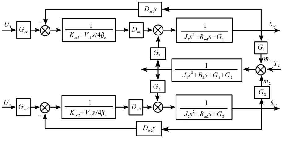
By integrating the above Eqs.(1)~ (5),the linear model block diagram of bi-motor position synchronization system could be obtained,as shown in the Figure 2.

Figure 2.Swinging bi-motor electro-hydraulic servo position synchronization system model
3.Analysis of synchronization error and design of synchronous controller
3.1.Influences of synchronization error
According to the above mathematical model,when rigid coupling is considered,the transfer function of two synchronization channels is different from that of the simple single-channel valve control motor position servo system.At this time,the two channels have mutual effect on output.Theoretically,when parameters of the two channels are the same,the position outputs of these two hydraulic motors are absolutely identical,so there will be no synchronization error[3-4].However,in practical engineering,machining error,assembly accuracy,and lubrication condition of various elements in the system are different.Major reasons for the generation of synchronization error are as follows:
1)Difference of structure parameters between the two motors.The hydraulic motors used for synchronous drive are designed symmetrically and assembled by pairing,but nobody can guarantee the absolute consistence for their structure parameters.In addition,with continuous working of the motor,sealing elements of the motor will wear out,so the structure parameters are inevitably time-depended.As a result,outputs of the two hydraulic motors will be out of synchronization,thus the synchronization error will occur.
2)Difference of servo valve characteristics:Dynamic and static characteristics of two-channel servo valve are different.For instance,the inconsistence of servo valve bandwidth and servo valve flow gain will also result in desynchrony in outputs of the two hydraulic motors.
3)Time varying characteristic of system parameter:Some parameters in the system will change with factors like working situations under dynamic working condition;for instance,channel gain and reaction coefficient will make outputs of two hydraulic motors different,thus synchronization error will be caused.
4)Mutual effect of dynamic working conditions of bi-motor:When the two motor are out of synchronization,one motor will become the load of other motor,thus the synchronization error will become bigger and bigger.
3.2.Design of synchronous controller
By directing at the characteristic that the system requires high frequency response and has time-varying characteristic,a synchronous controller based on fuzzy adjustment is proposed.As shown in Figure3,the synchronization theory is presented.This scheme is based on equivalent synchronization control method,which means to give the same position signal to two subsystems to be synchronized,and to provide approximate dynamic and static characteristics for them via two identical PID controllers.Various components of the two motor subsystems have the same theoretical parameters,but during actual operation,outputs of these two synchronous subsystems will be inconsistent due to time-varying characteristic of parameters and external interference,thus synchronization error e will be caused.This error acts on hydraulic motor 2 through the output of fuzzy controller to make outputθm2of motor 2 consistent with outputθm1of motor 1.Throughthis way,the purpose of synchronous control will be realized.According to Figure3,control variable that acts on servo valve 2 is composed of two parts.Except the part that is the same with the control variable of servo valve 1,there is also an additional control variable Uf.Function of this control variable is to eliminate synchronization error caused by inconsistence of synchronous subsystem characteristics under the equivalent way.Fuzzy adjuster is used to remove inner ring synchronization error,so this method is bi-motor synchronous drive fuzzy complex cross-coupling control[5].Fuzzy control is an intelligent control method based on fuzzy set theory,fuzzy language variable,and fuzzy logic reasoning,and it is a kind of nonlinear intelligent control.Mamdani fuzzy reasoning model is adopted in this paper.

Figure 3.Bi-motor synchronous drive crosscoupling controller model
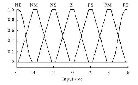
In bi-motor position synchronization fuzzy control system,position deviation e and deviation change rate ec are selected as input variables;PID gain adjustment amountΔKP,ΔKiand ΔKdare output variables.The fuzzy subsets of input and output variables are defined as E,EC,ΔKP,ΔKiand ΔKd={NB,NM,NS,Z,PS,PM,PB}.They represent{negative big,negative medium,negative small,zero,positive big,positive small,positive big},respectively.Domain of discourse of the input quantity is set as e and ec={-6,-4,-2,0,2,4,6}.Its subordinating degree function is shown in the following figure.

Figure 4.Subordinating degree function
The domains of discourse of output quantity ΔKP,ΔKiand ΔKdare ΔKP={-0.3,-0.2,-0.1,0,0.1,0.2,0.3};ΔKi={-0.3,-0.2,-0.1,0,0.1,0.2,0.3};ΔKd={-3,-2,-1,0,1,2,3}.
The adjustment principles of Kp,Kiand Kdare as follows:
When the deviation|e|is too big,the response speed of system with bigger Kpand smaller Kdshould be selected.In order to prevent too big overshoot,integral action can be removed to make Ki=0.When the deviation|e|has a medium value,one should select smaller Kpand moderate Kiand Kd,so as to decrease overshoot;besides,a high response speed should be maintained.When the deviation|e|is too small,in order to guarantee system stability,Kpand Kishould be increased;meanwhile,to avoid system vibration and enhance anti-jamming capability of the system,proper Kdshould be selected.In conclusion,specific fuzzy rule table should be made by combining with practical operation experience.

Table 1.Kp fuzzy control rule table

Table 2.Ki fuzzy control rule table

Table 3.Kd fuzzy control rule table
According to online tuning for PID parameters in the fuzzy rule table,the computation rule is:Kp=Kp0+ΔKP;the same with Kiand Kd.In this formula,Kp0,Ki0and Kd0are the initial PID parameters;ΔKP,ΔKiand ΔKdare the parameter output quantity.In this way,fuzzy controller will be able to adjust PID parameters continuously,so as to realize the purpose of real-time modification for motor 2.
4.Controller simulation analysis
By comprehensively considering theoretical analysis and actual working conditions,it was assumed that the two-channel servo valves are identical,but the leakage coefficients of the two motors are different.See Table 4 for the specific simulation parameters:
Firstly,simulation analysis is made for the equivalent control mode without fuzzy controller.The input signal is a sine voltage signal with the frequency of 7 Hz and amplitude of 20°.A conventional PID controller is adopted in the two channels.Parameters of these two conventional PID controllers are:Kp=0.8,Ki=0.7,and Kd=0.3.The following curve could be obtained after the simulation:

Table 4.Simulation parameter table
In Figure 5,curve 1 is the ideal signal angle;curve 2 stands for angular output of motor 1;curve 3 stands for angular output of motor 2;curve 4 indicates angular displacement difference of two motors.According to Figure 5,under situations without interference,the maximum position error of bi-motor is about 3°.If stiff shaft is not used to connect these two motors,the synchronization error will be greater.
After that,a cross-coupling fuzzy synchronous controller is added in this system.The input signal remains unchanged,i.e.,sine voltage signal with the frequency of 7 Hz and amplitude of 20°.At the same time,an interference torque signal of 500 is added to motor 1 at the time point of 4 s.The simulation results are presented in Figure 6.As shown in this figure,this controller could reduce the maximum synchronization error of bi-motor to about 1°.The synchronization precision has been increased,and all the design requirements of bi-motor electro-hydraulic servo control system were met.

Figure 5.Simulation result under equivalent control mode

Figure 6.Simulation result under cross-coupling fuzzy synchronous control mode
5.Conclusion
Mathematical model of swinging bi-motor electro-hydraulic servo position system was established in this paper.Based on the mathematical model,the mechanism of synchronization error and system characteristics of bi-motor synchronous drive were thoroughly analyzed.Through the fuzzy complex crosscoupling control mode,the synchronization error was introduced into the position control closed loop of motor 2 again.The synchronization precision of bi-motor position was improved in the system with hydraulic motor synchronous drive,thus the purpose of bi-motor synchronous control was realized.Structure of this system and design of synchronous controller have important significance for multi-actuator synchronous drive electro-hydraulic servo system with heavy load and high frequency response.
[1] LI Jun-wei,Zhao Ke-ding,WU Sheng-lin.Research on Dual Electrohydraulic Motors’Synchronization via Fuzzy Control[J].Machine Tool& Hydraulics,2003,01:115-116.
[2] LIU Chun-fang,Wu Wei.Research on Dual Electro-hydraulic Servo System Synchronization Based on Fuzzy Control[J].Chinese Hydraulics & Pneumatics,2005(9):19-21.
[3] WANG Yan-shan,LI Yun-hua,WANG Yi-qun.Five-axis Electro-hydraulic Simulator Dual Motors Synchronizing Control[J].Journal of Beijing University of Aeronautics and Astronautics,2008(4):408-411.
[4] WANG Kai,WANG Zhan-lin,QIU Lihua,et al.Hydraulic Simulator Outer Gimbal FNN Controller Design and Simulation[J].Journal of Beijing University of Aeronautics and Astronautics,2006,32(5):571-574.
[5] GUO Zhi-fu.Research on Quantitative Feedback Design Method of Hydraulic Flight Simulation[D].Harbin:Harbin Institute of Technology,2010.

