Three-dimension micro magnetic detector based on GMI effect
WEI Shuang-cheng(魏双成), DENG Jia-hao(邓甲昊), HAN Chao(韩超),Yang Yu-ying(杨雨迎)
(Science and Technology on Electromechanical Dynamic Control Laboratory, School of Mechatronics Engineering,Beijing Institute of Technology, Beijing 100081, China)
Three-dimension micro magnetic detector based on GMI effect
WEI Shuang-cheng(魏双成), DENG Jia-hao(邓甲昊), HAN Chao(韩超),Yang Yu-ying(杨雨迎)
(Science and Technology on Electromechanical Dynamic Control Laboratory, School of Mechatronics Engineering,Beijing Institute of Technology, Beijing 100081, China)
The giant magneto-impedance (GMI) effect of amorphous wire was analyzed theoretically. The amorphous wire had strong GMI effect in the stimulation of sharp pulse of 680 kHz and 18 mV. A pulse generator was designed to provide high frequency pulse to a magnetic impedance (MI) element. The induced voltage on the pickup coil wound on the amorphous wire was sampled and held with a detect circuit using analog switch. A stable magnetic sensor was constructed. A three-dimension micro magnetic field detector was designed with a central controller MSP430F449. High stability and sensitivity were obtained in the MI sensor with the detect circuit. Experiment results showed that the resolution of the detector was 1nT in the full scale of ±2 Oe and the detector worked stably from the room temperature to about 80 ℃. A small ferromagnetic target was detected by the three-dimension detector in laboratory environment without magnetic shielding. The target moving direction was ascertained with the wave shape of axis parallel in that direction.
giant magneto-impedance (GMI) effect; amorphous wire; three dimension detector; pulse generator; analog switch
Amorphous wire with nearly zero magnetostriction of -10-7is one of the most promising materials to make magnetic sensors. When high frequency pulse current is applied to amorphous wire, the impedanceZof the amorphous wire changes with the external magnetic field due to the skin effect. The phenomenon is called GMI effect[1]. Compared with conventional magnetic sensors such as Hall sensor, GMR effect sensor and flux sensor, GMI sensor has the characteristics of high sensitivity, quick response, temperature stability, small size and low energy consumption.
To get a high sensitivity magnetic sensor, the amorphous wire must work in a high MI ratio which represents the GMI effect level. MI ratio is defined as

(1)
Here,Z(H) represents the impedance of the amorphous wire under magnetic fieldH,andZ(Hmax) represents the impedance of the amorphous wire under saturated magnetic fieldHmax. The impedance of amorphous wireZcan be expressed as[2]
(2)
Here,J0(ka) andJ1(ka) are zero order and one order Bessel functions respectively,Rdcis the resistance of amorphous wire in the dc current,ais the radius of amorphous wire,δis the penetration of the stimulating current,ρis the conductivity of amorphous wire,μis circular magnetic permeability of amorphous wire andωis the circular frequency of current pulse. When the pulse frequency increases more than 200 kHz, the skin effect in amorphous wire becomes remarkable and the GMI effect becomes strong. The impedance of amorphous wire in the strong skin effect can be expressed as[3]
(3)
TheprincipleofGMIeffectintheamorphouswireisillustratedinFig.1.TheexternalmagneticfieldHexis applied parallel to the amorphous wire axis. The induced voltage proportional toHexdue to GMI effect can be detected via checking coil wound on the amorphous wire. The output voltage can be adjusted with a negative feedback coil.
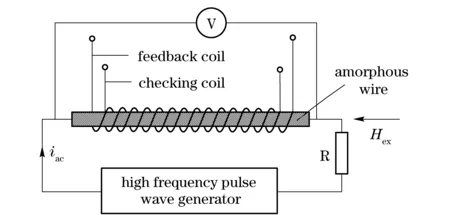
Fig.1 Principle of GMI effect in amorphous wire
1 High frequency pulse generator
As illustrated in Fig.1, as-cast amorphous wires (Co94Fe6)72.5Si12.5B15were adopted to make MI elements. The wires were 2 mm in length and 30 μm in diameter wound with a feedback coil and a checking coil. To get strong GMI effect in the wires, a high frequency pulse generator was designed with MAX038. The circuit of the pulse generator was shown in Fig.2.
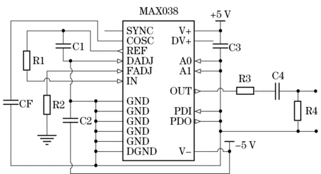
Fig.2 Circuit of high frequency pulse generator
The pulse voltage, frequency and wave form of the generator could be adjusted conveniently. The frequency of pulse was regulated by CF and R1 and the voltage amplitude was regulated by R3. A square wave of 680 kHz with 50% duty ratio was obtained at the output port of MAX038 when voltage levels of the ports A0, A1 and DADJ were low. As studied before[4], the rise time of the pulse is important to GMI effect. The shorter rise time of pulse wave the stronger GMI effect in the amorphous wire. To get strong GMI effect, sharp pulse shall be applied to the amorphous wire. The differential coefficient circuit of C4 and R4 converted the square wave to sharp pulse within 10 ns rise time. The pulse current with frequency of 680 kHz was applied to the amorphous wires, and the voltage amplitude between both ends of the wire was about 18 mV. The sharp pulse voltage wave on the ends of amorphous wire was measured with Tektronix oscillograph. The pulse wave was illustrated in Fig.3.
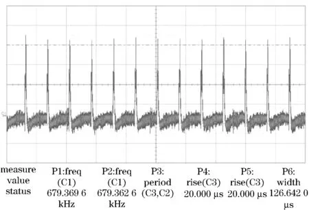
Fig.3 Sharp pulse waveform of the high frequency pulse generator
2 Detect circuitry of MI sensor using analogy switch
When an ac current is applied in the amorphous wire, the induce voltage on the pickup coil wound on wire changes with the externalHex. The voltage can be sampled and held by an analogy switch circuit. To get a highly stable sensor, a pair of MI elements was matched to a balanced circuit shown in Fig.4. The analog switch has many advantages in the sample and hold circuit. Pickup coils can isolate the electrical elements, the analog switches can detect the first voltage pulse synchronously, the common mode noises can be cancelled by balance circuitry and the negative feedback loop can stabilize the output voltage[5]. For above referred reasons, the magnetic sensor showed a stable performance.
The detection circuit using an analog switch was illustrated in Fig.4. The output voltage of the sensor is proportional to the external magnetic fieldHexin high linearity. The analog circuit could obtain temperature stability from the room temperature to about 80 ℃. In addition the sensor had high linearity at a full scale of ±2 Oe.
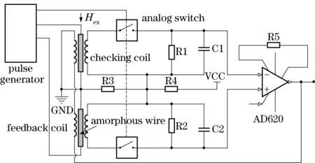
Fig.4 Detect circuit with analog switch
3 Design of magnetic detector
On the base of sensitive and stable MI sensors, a three-dimension magnetic detector was constructed with the kernel controller MSP430F449. The detector was composed of a high frequency pulse generator, MI sensors, sample and hold circuits, a signal preprocess circuit, a key controller MSP430F449, RAM and power source units. The detector frame was illustrated in Fig.5. The pulse generator generated sharp pulse which was applied to the amorphous wire to induce the inductive voltage proportional to the externalHex. The inducing voltage on pickup coil was sampled and converted to the controller F449. Three MI sensors were installed vertically with each other in the detector. Each sensor detected one vector component of the magnetic fieldHex.

Fig.5 Frame of the micro magnetic field detector
4 Ferromagnetic target detect experiments in laboratory
Detection experiments were performed in a laboratory environment without the magnetic shielding. An electrical heater was applied to adjust the air temperature around the detector in order to investigate the detector temperature stability. A small ferromagnetic target of 10 mm length and 10 mm diameter was moved along the line 500 mm away from the detector. The moving direction was parallel to theXaxis of the detector. The detector detected the target and recorded the data in a RAM. With the recorded data the magneto-voltage characteristics were calculated and drawn in waves on a computer. The target characteristic waves of three axes were illustrated in Fig.6.
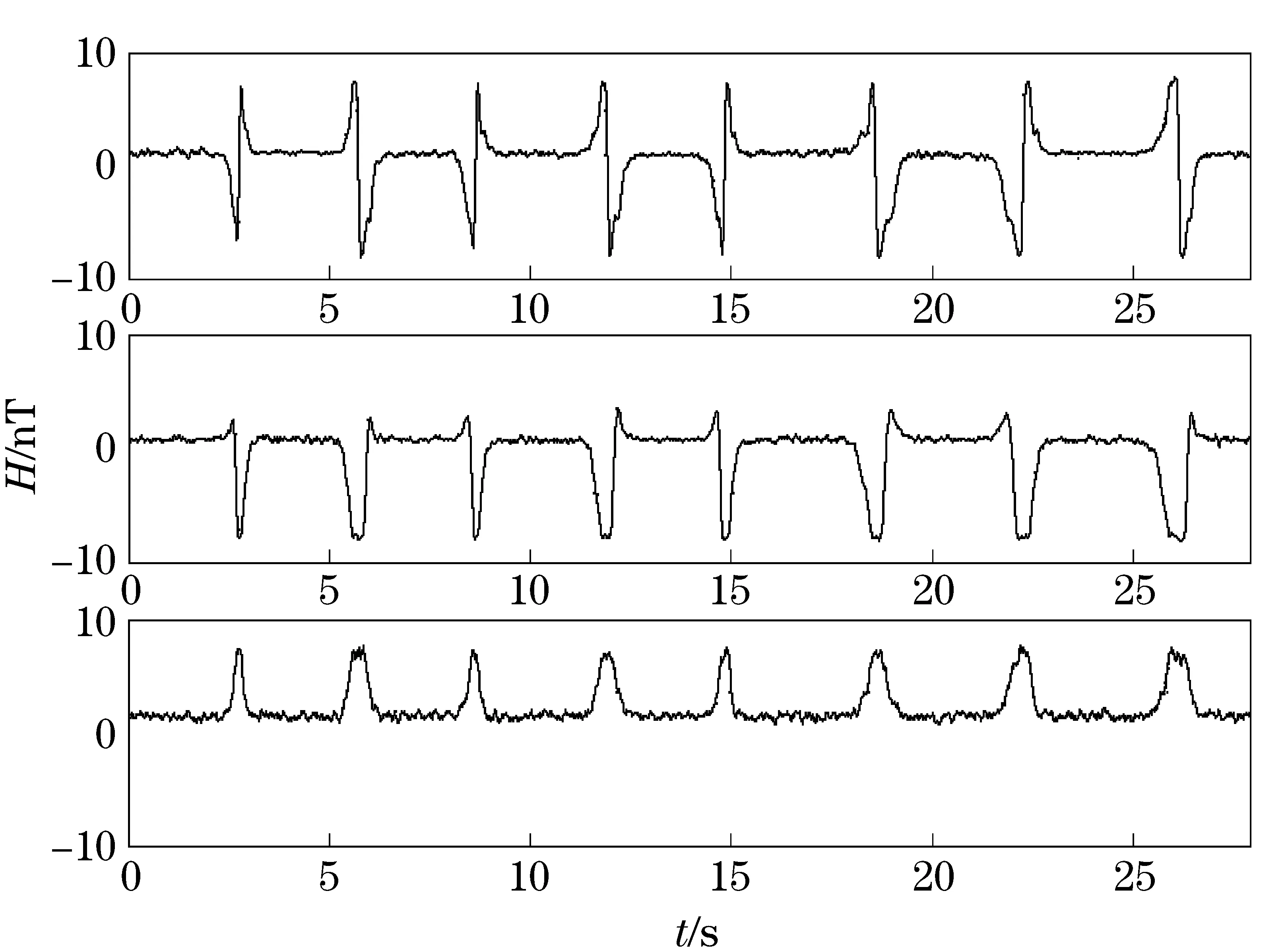
Fig.6 Waves of small ferromagnetic target
The wave of each direction was different from each other. The wave form ofXaxis which is parallel with the target moving direction changed remarkablly, compared with those ofYandZaxis. The moving direction of the target could be ascertained by the wave form of theXaxis. The induced voltage on theXaxis increased first and decreased immediately to the minimum when the target passing by the detector. Then the voltage increased again when the target passed away the detector. If the target moved in adverse direction, the induced voltage on MI sensorXchanged inversely. The experiment results showed that detector had resolution of about 1nT and worked stably from the room temperature to about 80 ℃.
5 Conclusion
The experiment results indicated that the detector could detect small ferromagnetic targets of low magnetic field. The detector had stable performance from the room temperature to 80 ℃
and had a high resolution. The magnetic field could detect three magnetic vector components of the ferromagnetic target. The detector resolution at the full scale of ±2 Oe was 1nT. The detector could be used to detect large ferromagnetic targets from far distance.
[1] Mohri K, Kohzawa T, Kawashima K, et al. Magneto-inductive effect (MI effect) in amorphous wires[J]. IEEE Transactions on Magnetics,1992, 28(5):3150-3152.
[2] Vulfovich P J, Panin L V. Magneto-impedance in co-based amorphous wires and circular domain dynamics[J]. Sensors and Actuators, 2000, 81: 111-116.
[3] Kawajiri N, Nakabayashi M, Cai C M, et al. Highly stable MI micro sensor using C-MOS IC multi-vibrator with synchronous rectification[J]. IEEE Transactions on Magnetics, 1999, 35(5): 3667-3669.
[4] BushIda K, Mohri K, Kanno T, et al. Amorphous wire MI micro magnetic sensor for gradient field detection[J]. IEEE Transactions on Magnetics, 1996, 32(5):4944-4996.
[5] Nakamura Y, Uchiyama T, Cai C M, et al. PWM-type amorphous wire CMOS IC magneto-impedance sensor[J]. IEEE Transactions on Magnetics, 2008, 44(11): 3981-3984.
(Edited by Wang Yuxia)
2013- 01- 08
Supported by the National Natural Science Foundation of China(60874100)
O 482.54 Document code: A Article ID: 1004- 0579(2014)02- 0143- 04
E-mail: weigter@163.com
 Journal of Beijing Institute of Technology2014年2期
- Journal of Beijing Institute of Technology的其它文章
- Expert ranking method based on ListNet with multiple features
- Investigating fatigue behavior of gear components with the acoustic emission technique
- Contour tracking using weighted structure tensor based variational level set
- Consensus problem of multi-agent systems under arbitrary topology
- One-piece coal mine mobile refuge chamber with safety structure and less sealing risk based on FEA
- On measured-error pretreatment of bionic polarization navigation
