Interior ballistic simulation and parameter influence analysis of an underwater pneumatic launcher*
Qing-yong NIU, Tian-yun LI
1School of Naval Architecture and Ocean Engineering, Huazhong University of Science and Technology, Wuhan 430074, China;2Ships and Marine Hydrodynamics Key Laboratory of Hubei Province, Wuhan 430074, China
Interior ballistic simulation and parameter influence analysis of an underwater pneumatic launcher*
Qing-yong NIU†1,2, Tian-yun LI1,2
1SchoolofNavalArchitectureandOceanEngineering,HuazhongUniversityofScienceandTechnology,Wuhan430074,China;2ShipsandMarineHydrodynamicsKeyLaboratoryofHubeiProvince,Wuhan430074,China
An underwater pneumatic launcher was studied to analyze its interior ballistic characteristics. Using mathematical modeling method, the interior ballistic model was established. The influences of three parameters were discussed including the critical moving resistant force, the maximum open area of the launch valve and the initial inflation air-bottle pressure. The results show that the maximum chamber pressure is mainly determined by the critical resistant force, and the exit velocity of the weapon out of the launch tube is mainly determined by the initial inflation air-bottle pressure and the maximum open area of the launch valve.
Launcher, Mathematical modeling, Interior ballistic, Parameter influence analysis
1.Introduction
For a certain type of underwater pneumatic launcher, compressed air is used as energy source to thrust the weapon out of the launch tube at a designed velocity. The study of the interior ballistic has great significance in the optimization design of the launcher and the pre-estimation of the launch experiments. For confidentiality reasons, literatures related to this type of launcher could rarely be collected. But owing to the similarity to other types of launchers such as torpedo launchers in some aspects, this type of launcher could be mathematically modeled by using the references provided by torpedo launchers. Compressed-air torpedo launcher, hydraulic balanceable torpedo launcher and air-turbine pump launcher were extensively studied by WANG Shu-zong[1], HU Bai-shun[2], TIAN Bing and LIAN Yong-qing[3-5], WU Zhao-hui, et al[6]. Among these studies, each component of the launch system was separately mathematically modeled and then the launch system was analyzed as a whole.
However, because of the difference in sealing mechanism and the weapon external geometry, the interior ballistic performance of this type of pneumatic launcher distinguishes from that of torpedo launchers. In this research thermal and dynamic theories are used to establish the interior ballistic model of this launcher. For interior ballistic parameters which affect the maximum chamber pressure and the exit velocity of weapon, their influence law is discussed and some useful conclusions are obtained.
2.Mathematical model
A type of underwater pneumatic launch, which is shown in Figure 1, has a sealing cover at its end. The metal film, which prevents the weapon inside the launch tube from being soaked wet, would be cut off during launch. The initial resistance force needed to cut off the sealing metal film ensures a certain exit velocity of the weapon out of the launch tube. Based on thermal and dynamic equations for the air-bottle, the launch valve, the launch tube, the weapon and the launch system could be mathematically modeled and analyzed.

Figure 1. Schematic diagram of an underwater pneumatic launcher
2.1.Model of the air-bottle
According to the ideal-gas equation of state and the adiabatic process equation, the pressure and temperature inside the air-bottle during launch could be written in forms of:
(1)
(2)
in whichTB0,pB0,mB0andTB,pB,mBare the air-bottle temperature (K),pressure (Pa) and mass (mg) at the initial time (defined as the time at which the launch valve begins to open) and during the launch process.κrefers to the adiabatic index.
2.2.Mass flow through the launch valve
Ignoring the air leakage during the launching process, the mass flow from the launch valve into the launch tube has an empirical expression[7]:
(3)
whereφis the flow coefficient of the launch valve, ranging from 0.6 to 0.65;ρiis the air density at the outlet section of the launch valve (kg/m3);uiis the air velocity at the outlet section of the launch valve (kg/m3). According to the theory of the nozzle flow[8], the velocity and air density at the outlet of the valve are written as follows:
in whichR=287 J/(kg·K) is the gas constant;pCis the air pressure inside the launch tube during launch (Pa);β=[1/(κ+1)]κ/(κ-1)is the critical pressure ratio. The temperature at the outlet of the launch valve is:
(6)
in whichpiis the corresponding pressure (Pa).
2.3.Opening law of the valve
The opening law of the launch valve plays important role in the control of the interior ballistic. Generally, the open law could be expressed as a continuous function or piecewise function of time. WLOG, the valve could be assumed as an ideal quick-opening valve whose open law is shown in Figure 2. In Figure 2,t0is the full-open time of the valve, andAV0is the maximum open area.
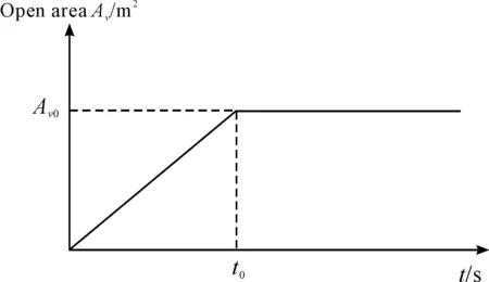
Figure 2. Open area of the launch valve
2.4.Model of the launch tube
Defining the initial inflated volume as the sum volume of the valve, pipe and the chamber of the launch tube and ignoring the heat exchange between air and the tube wall, the property of air inside the launch tube is described by the first law of thermodynamics:
(7)
in whichUCis the internal energy (J) left inside the launch tube, whereasUC0is the initial internal energy (J);Hiis the thermodynamic enthalpy (J) of the air flowed from the launch valve to the launch tube;Wis the work (J) of the thrust force acting on the weapon. Inside the launch tube, the temperatureTCand pressurepCare expressed as:
(8)
(9)
wheremCis the air mass (kg) inside the launch tube;cVis the specific heat at constant volume J/(kg·K);VCis the instantaneous air-inflated volume of the launch tube (m3). The injection rate of the heat enthalpy through the launch valve to the launch tube is dHi/dt=cpTBdmi/dt, wherecpis the specific heat at constant pressure J/(kg·K). Considering the throttling action of the launch valve, the stagnation temperature decreases slightly:
(10)
Therefore,
(11)
The change rate of air mass inside the launch tube is:
(12)
After the open of the launch valve, the pressure inside the tube increases rapidly and the weapon is pushed outward by the thrust force. In this process, the change rate of the air-inflated volumeVCinside the launch tube is:
(13)
in whichSis the intersection area of the weapon (m2);vgis the moving velocity of the weapon (m/s);Fcris the critical force the weapon needed to overcome as it starts to move (N).
2.5.Motion law of the weapon
The motion of the weapon satisfies dynamic equation:
(14)
in whichmgis the weapon mass (kg);xis the displacement inside the tube;Rgis the resistant force of the metal sealing film which is needed to overcome as the weapon starts to move:
(15)
whereρwis the density of water (kg/m3);CDis the moving drag coefficient of the weapon;μis the friction coefficient between the weapon and the launcher wall;Gis the weight of the weapon (N);phis the fluid pressure outside the launch tube.
The power of the thrust force acted on the weapon is:
(16)
3.Typical launch analysis and validation
Equations (1) ~ (16) form a mathematical model describing the launch process. Given the open law of the launch valve, the launching process could be calculated. Using MATLAB, the differential equations is numerically simulated.
In order to validate the reasonability of the mathematical model, water tank experiments are carried out. The main experiment parameters are as follows: air-bottle volume 0.04 m3, initial volume of the launch tube 0.032 m3, specific heat at constant pressurecp1 006 J/(kg·K), specific heat at constant volumecV719 J/(kg·K), and weight of the weapon 100 N. The internal travel length of weapon inside the launch tube is 0.8 m. The critical resistant force of the weaponFcris 9 000 N determined by experiments. The open time of the valve is 50 ms, and the maximum open area is 20 mm2. The moving drag coefficientCDis 0.8. Step size Δtfor numerical calculation is 0.001 s. The air-bottle initial inflation pressure is 2.50 MPa.
The results of the theoretical model with the same parameters as experiments, contrasting with the results of experiments, are listed in Table 1.

Table 1. Results contrast between theoretical analysis and experiments
It can be seen from Table 1 that the results between the theoretical model and the experiments agree well with each other. The effectiveness of the model simulation is validated.
4.Parameter analysis of the interior ballistic
For the launcher, the maximum chamber pressurepC,maxand the exit velocity of the weaponvg,exitare the most important indicators of the interior ballistic. Hence,pCandvgare chosen as the target functions. The initial resistant forceFcr, the maximum open area of the launch valveAV0and the initial inflation pressure of the air-bottlepB0are chosen as variables to study their effects. For the convenience of comparison, relative change of each parameter is set to the same magnitude (±10%, ±20%), starting from the corresponding simulation parameter.
4.1.Initial resistant force
The variation of the thickness of the sealing metal film directly leads to the difference of the critical motion resistant forceFcrof the weapon, and has great significance in the interior ballistic. DifferentFcr(7 200, 8 100, 9 000, 9 900, 10 800 N) are studied to evaluate their effect on the target functions. Figures 3~4 give the changes ofpCandvgwith time.
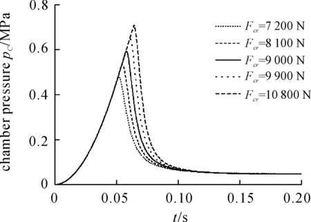
Figure 3. Chamber pressure curves of different Fcr
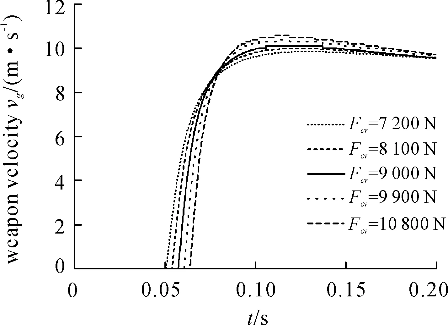
Figure 4. Weapon velocity curves of different Fcr
It is observed from Figures 3~4 that with the increase ofFcr, the maximum chamber pressurepC,maxincreases. The time required for the weapon to move becomes longer asFcrincreases.
4.2.Maximum open area of the launch valve
Five maximum open areas of the launch valveAV0(5, 10, 15, 20, 25 mm2) are discussed to evaluate their differences on the interior ballistic. Figures 5~6 show the curves ofpCandvgwith time.
Figures 5~6 show that the maximum chamber pressurepC,maxkeeps unchanged but the time to gain peak value becomes shorter as the maximum area of the launch valveAV0increases. Weapon velocityvgalso increases when the maximum open area of the lunch valveAV0increases.
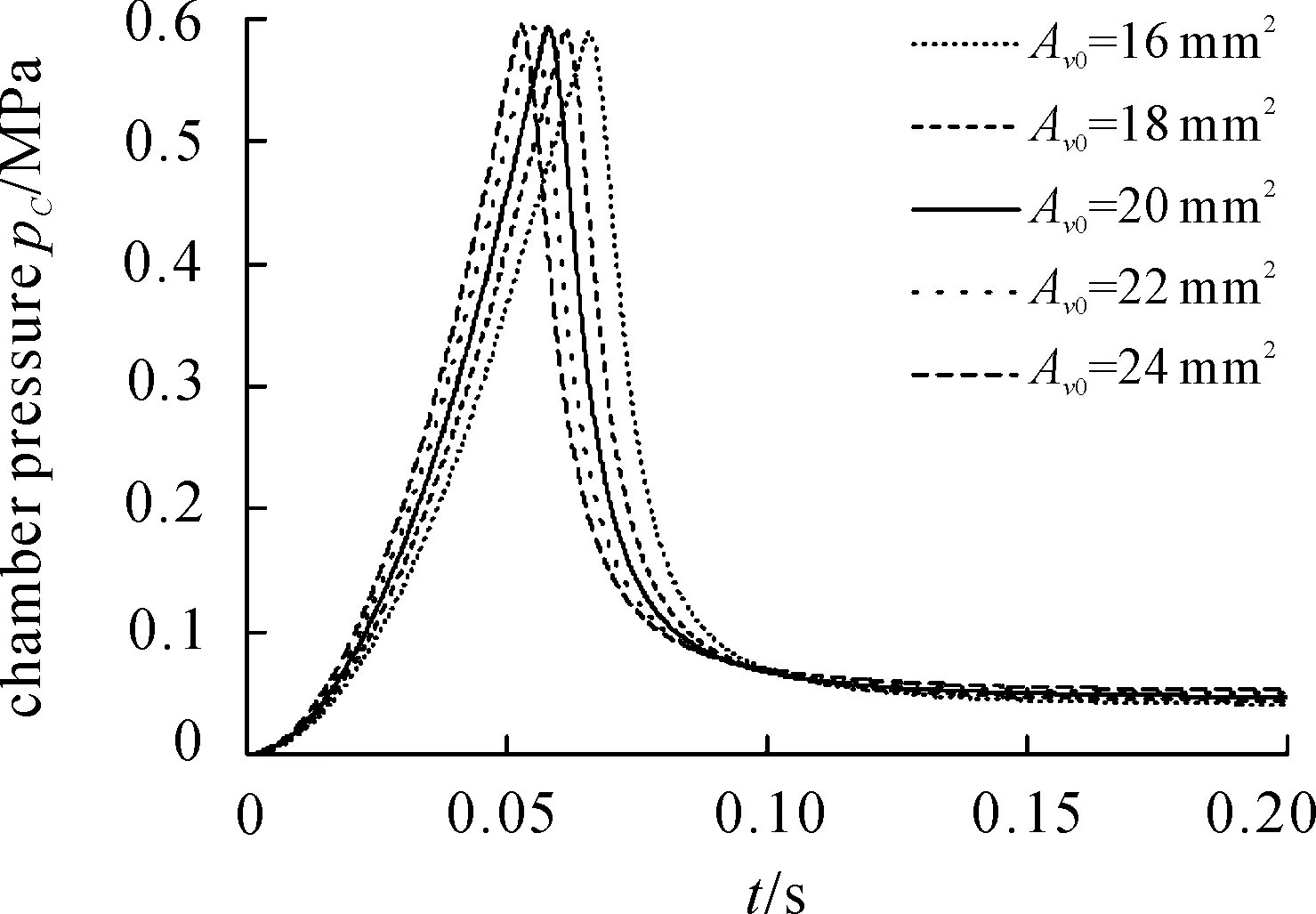
Figure 5. Chamber pressure curves of different AV0
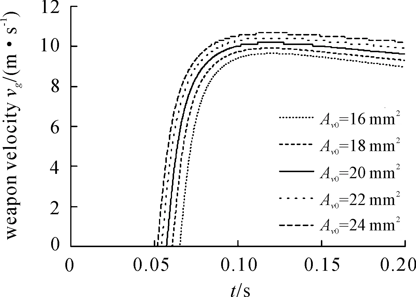
Figure 6. Weapon velocity curves of different AV0
4.3.Initial inflated pressure of the air-bottle
Five different initial inflation pressurepB0(1.5, 2.0, 2.5, 3.0, 3.5 MPa) of the air-bottle are studied to gain their influence on the changes ofpCandvgwith time shown in Figures 7~8.
It’s shown in Figure 7 that the maximum chamber pressure keeps almost unchanged but the time forpCfrom 0 to peak value becomes shorter with the increase ofpB0. The weapon exit velocityvgincreases significantly as the initial inflation pressure of the air-bottlepCincreases.

Figure 7. Chamber pressure curves of different pB0

Figure 8. Weapon velocity curves of different pB0
5.Conclusion
A mathematical model of an underwater pneumatic launcher is established to simulate its interior ballistics. Parameters of initial resistant force, maximum open area of the launch valve, initial inflation pressure of the air-bottle are analyzed to study their influences on the interior ballistic. Results show that the maximum chamber pressure is mainly determined byFcr, and hardly affected byAV0andpB0. Exit velocity of the weapon is mainly determined byAV0andpB0.
[1] WANG Shu-zong, LIAN Yong-qing, CHEN Yi-diao. The mathematical model of the underwater compressed air launcher[J]. Journal of Ballistics, 2003,15(1):21-26.
[2] HU Bai shun, MU Lian-yun, ZHAO Zuo-de. Simulation and model of submarine hydraulic and balanceable launching equipment inside trajectory[J]. Ship Science and Technology,2011,33(7):90-93.
[3] TIAN Bing,Wang Shu-zong, LIAN Yong-qing. Inner Trajectory modeling and Simulation of hydraulic energy accumulated torpedo launcher[J]. Torpedo Technology,2011,19(1): 68-71.
[4] LIAN Yong-qing, XU Qin-chao,WANG Shu-zong. Simulation of startup process of air turbine with load[J]. Chinese Journal of Mechanical Engineering,2011,47(8): 68-71.
[5] LIAN Yong-qing,TIAN Bing,WANG Shu-zong, et al. Simulation and analysis of the launching process of air-turbine pump launch system[J]. Acta Armamentarii, 2011,32(2):155-162.
[6] WU Zhao-hui, WANG Shu-zong, MA Shi-jie. Building model and simulation of submarine rotary pump torpedo launch system[J]. Journal of naval university of engineering, 2000(5):54-58.
[7] QIAO Ru-chun. A design analysis of pneumatic turbine pump-type submarine torpedo launcher[J]. Torpedo Technology, 2004,12(2): 43-46.
[8] SHEN Wei-dao,JIANG Zhi-min, TONG Jun-geng. Engineering thermodynamics[M]. Beijing: High education press,2001.
水下气动发射装置内弹道仿真和参数影响分析*
牛清勇†1,2,李天匀1,2
1.华中科技大学 船舶与海洋工程学院,武汉 430074;2.船舶和海洋水动力湖北省重点实验室,武汉 430074
对某水下气动发射装置进行了理论分析,研究了其内弹道特性。利用数学建模方法对发射过程进行了建模并对内弹道性质进行了计算。对影响内弹道性能的3个主要参数:武器运动的初始阻力、发射阀最大开启面积和发射气瓶初始充气压强进行了分析。计算结果表明:发射管最大膛压的主要影响参数为武器运动初始阻力;而武器出管速度的主要影响参数为发射气瓶初始充气压强和发射阀的最大开启面积。
发射装置;数学建模;内弹道;参数影响分析
TJ6
2014-03-15
10.3969/j.issn.1001-3881.2014.12.001
*Project supported by National Natural Science Foundation of China (No.51078375)
† Qing-yong NIU, PhD.E-mail:qyniu@163.com
- 机床与液压的其它文章
- A Simple time-domain method for bearing performance degradation assessment*
- Impacts of centrifuge errors on calibration accuracy of error model coefficients of gyro accelerometer*
- Design of special fixture for automatic measurement of resistance of auto ignition wire*
- Tool wear monitoring based on wavelet packet coefficient and hidden Markov model*
- Structural design and performance testing of the electromagnetic proportional pressure relief valve
- Influence of airflow uniformity over the duct outlet of vehicle air-condition on cooling performance*

