
Spray Characteristics Study of Combined Trapezoid Spray Tray
2014-07-25 10:01HeLiangLiChunliLiuJidongXieZhenshan
中国炼油与石油化工 2014年3期
He Liang; Li Chunli; Liu Jidong; Xie Zhenshan
(School of Chemical Engineering and Technology, Hebei University of Technology, Tianjin 300130)
Spray Characteristics Study of Combined Trapezoid Spray Tray
He Liang; Li Chunli; Liu Jidong; Xie Zhenshan
(School of Chemical Engineering and Technology, Hebei University of Technology, Tianjin 300130)
The spray behaviors of the combined trapezoid spray tray (CTST) have a significant effect on the gas-liquid interface. In this paper, the spray process of CTST in a column, 570 mm in diameter, was experimentally investigated by using a high-speed camera, and a theoretical model of the average droplet size was established according to the unstable wave theory. The results demonstrated that gas velocity passing through the hole is the key factor affecting the spray angle, which increases gradually with an increase in the gas velocity. When the gas velocity exceeds 7.5 m/s, the spray angle becomes stable at around 55°. The average flow velocity of the liquid sheet at the spray-hole increases significantly with an increase in the gas velocity, and decreases slightly with an increase in the liquid flow rate; moreover, it increases from the bottom of spray hole upward to the top. The density of liquid drops distribution in the spray area can be described by the Rosin-Rammler function. In addition, the liquid drops are mainly concentrated in the area of spray angle ranging from 20° to 40°, and they gradually become uniform with the increase in the gas velocity and the liquid flow rate. The average liquid drop size deceases with an increase in the gas velocity, and increases slightly with an increasing liquid flow rate. In the normal working range, the average liquid drop size is about 1.0 mm to 2.5 mm in diameter.
CTST; spray angle; gas velocity; distribution density; average flow velocity of liquid sheet; droplet size
1 Introduction
The combined trapezoid spray tray (CTST) is a sort of spray tray[1], the characteristics of which should be uplifting the liquid on tray, transferring the liquid to spray flow and breaking the spray flow into scattered droplets to obtain greater gas-liquid interface. For CTST, the masstransfer of droplets generated from breaking spray flow outside the cap accounts for 20%—35%[2]of the overall mass-transfer quantity. Therefore, the study on the spray process and characteristics of CTST is signi ficant in optimizing the cap structure, improving the mass-transfer ef ficiency and reducing the entrainment.
Numerous researchers[3-6]apply the theory of spray flow breaking, which has frequently been used to analyze the spray characteristics of equipment by several groups. They have found out that spray flow breaking is resulted from unstable wave generated on the surface of spray flow. The unstable wave includes two modes, viz. the sinusoidal and varicose waves. Through analysis on unstable wave, the dispersion equations in different modes can be obtained to describe the development and amplification of unstable wave[8-10]. Some researches[11-12]have worked out the average drop size by analyzing the length of unstable wave when the spray flow is breaking down.
2 Experimental
The diameter of experimental column is 570 mm, and the system is composed of an air-water system with the experimental facilities shown in Reference [2]. The cap of single spray-holes/side was used to eliminate the mutual effect between spray-holes in exterior spray function, the model of which measures 30 mm×80 mm×170 mm (width×length×height) in three dimensions. A round spray–hole, 10 nm in diameter, was employed. The thickness of spray tray is 2 mm, the dip angle of which is 8° against the vertical direction. The operation of the experimental equipment is shown in Figure 1. The real-time location of liquid sheet and droplets is obtained by means of a PowerView HS-650 high-speed camera.
The kinetic energy factor range of gas passing through the breadboard hole is 10~17 m/s (kg/m3)0.5and the average gas velocityugafter conversion is 5~10 m/s, which is theoptimal value of industrial design data. Liquid flow refers to the liquid quantity lifted by gas within the cap, which has an influence on both of the thickness and the average flow velocity of liquid sheet. This value can be obtained based on the lifted liquid quantity[13].
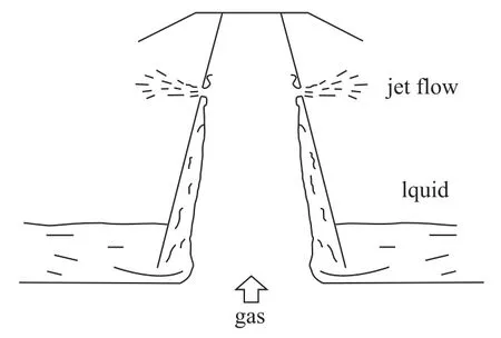
Figure 1 Scheme of operation of experimental equipment
3 Results and Discussion
After entering the cap, a liquid sheet is formed[14]and is clinging to spray tray wall under the effect of uplifting gas. The surface of liquid sheet waves can lose stability under the effect of gas shear force, separating some liquid from liquid sheet and forming small droplets. When the two-phase gas-liquid flow consisting of liquid sheet, droplets and uplifting gas reaches the spray-hole, a part of the gas is scattered outside the cap through spray-hole, enabling the uplifting liquid sheet clinging to spray tray to change movement direction and spray outside along with gas under the effect of aerodynamic force. The other part of spray forms scattered droplets within the cap, which can also be sprayed outside along with the gas. After leaving the spray-hole, the liquid sheet moves above the diagonal. Under the effect of unstable wave on surface, the liquid sheet in the middle and at the bottom end of spray-hole can be broken first to form scattered droplets. Under the effect of velocity vector in vertical direction, the unbroken liquid sheet gathers at the top end of sprayhole, which can be broken into droplets under the effect of aerodynamic force finally.
3.1 Influence of gas velocity passing through the spray-hole and liquid flow on the spray angle
In order to eliminate the influence of droplet falling back track, it is recognized that at a certain angle all droplets sprayed out from the spray-hole would not fall down. This angle is called the spray angle (α), horizontal direction of which is the zero base line for spray angle, as shown in Figure 2.
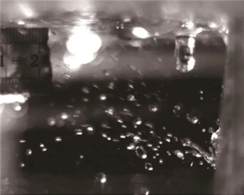
Figure 2 Scheme of the spray angleα
Figure 3 demonstrates the influence of gas velocity for spray-holeugand liquid flowQon spray angleα. The spray angle increases greatly with an increasing gas velocity. When the gas velocity reaches 7.5 m/s, the spray angle will gradually become stable. The kinetic energy obtained by droplet will be more and the uplifting distance of droplet will be greater along with the increase in gas velocity. The uplifting distance will not increase unlimitedly with the increase in gas velocity because of the limitation of sprayhole structure. When the liquid quantity increases, the spray angle will tend to amplify. Compared with the gas velocity, the influence of liquid flow on spray angle will be much less. It demonstrates that the aerodynamic force is the main factor for determining the range of droplets distribution.
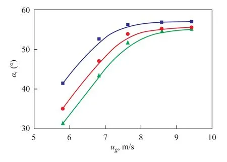
Figure 3 Dependence of α on ugand Q
3.2 Influence of gas velocity passing through the spray-hole and liquid flow on the average flow velocity of the liquid sheet
Figures 4 and 5 show the relationship between the aver-age flow velocity of the liquid sheet (uL), gas velocity for spray-holeugand liquid flowQ, respectively. It can be seen from the figures that, the acceleration effect of gas on liquid sheet enhances and the average flow velocity of the liquid sheet tends to increase with the increase in gas velocity. And the average flow velocity of the liquid sheet becomes larger when it is closer to the top of the sprayhole, whereas the influence of the gas velocity on the liquid sheet velocity becomes smaller.
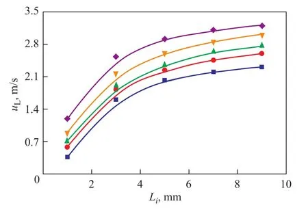
Figure 4 Dependence of uLon ug(Q=15 L/h)
In general, the influence of liquid flow on the average flow velocity of the liquid sheet is unobvious. When the liquid flow increases, the average flow velocity of the liquid sheet at the bottom of spray-hole decreases slightly; whereas no obvious changes can be observed in the middle and at the top end. The aerodynamic force in the lower-middle-part of liquid sheet is relatively small, and the energy consumed by liquid sheet during acceleration therefore accounts for a majority of the gross energy of aerodynamic force. The energy needed by liquid sheet for acceleration increases with the increase in liquid flow, and the consumption of aerodynamic force is thus much more obvious. While in the middle and at the top part of sprayhole, the gas velocity is relatively large and the aerodynamic force is much larger than the liquid mass force, therefore, the changes in liquid flow have little influence on the average flow velocity of the liquid sheet.
Figure 5 Dependence of ulon Q (ug=5.8 m/s)
3.3 Influence of gas velocity passing through the spray-hole and liquid flow on droplets distribution density
The percentage of droplets number accounting for the total number within a certain interval [(j-5)°,j°] of spray angle is the distribution density, which is represented byP. Figure 6 and Figure 7 demonstrate the influence of gas velocity and liquid flow on the distribution density of droplets, respectively. The density of droplets distribution can roughly be expressed by the Rosin-Rammler function[15]and the liquid droplets are concentrated in the areaof spray angles ranging between 20˚ and 40˚.
Figure 6 Dependence of P on ug(Q=15 L/h)
Figure 7 Dependence of P on Q (ug=5.8 m/s)
Figure 8 describes the distribution of the gas velocity in the spray hole. The results shown in Figure 8 were obtained by simulation with the RNGk-εturbulent model being adopted. The results were obtained using the SIMPLEC algorithm and non-static method. Parameters such as pressure, momentum,k,ε, etc. were obtained by using the second-order upwind algorithm. The boundary conditions are:
(1) Wall boundary condition: no slip took place near the wall and the Nallasamy logarithm wall function was adopted.
(2) Inlet condition: The cross section of the tower at 30 mm below the tray was chosen as the inlet where the gas velocity was constant and perpendicular to the cross section. It can be calculated based on:
whereVrepresents the gas volume,Drepresents the diameter of tower andugis the gas velocity.
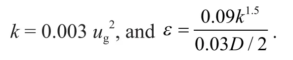
Hencekandεcan be obtained according to
(3) The outlet condition was the pressure boundary condition and the pressure at outlet was the same as the atmospheric pressure.
The maximum gas velocity can be observed within the above mentioned spray angle, which results in a stronger shearing force to increase the fluctuation of liquid surface and promote the breaking and distribution of the liquid.
Besides, the increase in both of gas velocity and liquid flow can make the distribution density of droplets within the spray angle become more uniform. The increase in gas velocity magnifies the aerodynamic force of the whole spray-hole. The liquid sheet in a rising state at the bottom end of spray-hole can be broken promptly along with the increase in gas velocity. The formation of droplets from the liquid gathering at the top of spray-hole becomes much easier in virtue of the remarkably increased aerodynamic force, enabling the droplet distribution density in the whole area to tend to be uniform. While the increase in the liquid flow amplifies the uplifting resistance, a part of liquid sheet is therefore blown outside the cap and then broken down during the uplifting process. Consequently the liquid quantity has a more significant effect on the droplets distribution density within the range of 5°— 20°.
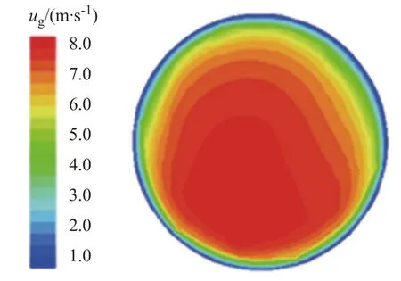
Figure 8 Gas velocity distribution in jet hole
4 Mathematical Description of Spray Process
4.1 Mathematical analysis of spray process
According to the Senecal linear stability analysis[16], when the Weber value is less than 27/16, the unstable wave caused the breaking of liquid sheet will be developed in the form of long wave, the dispersion relation of which is:
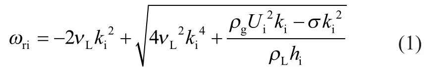
in whichωri,ki,hiandLirefer to the increase rate of unstable wave, wave number and half of liquid sheet thickness, respectively;vandρrefer to the kinematic viscosity and density, respectively; the subscript g denotes the gas and L denotes the liquid; andσrefers to the coef ficient of surface tension.Uiis the gas-liquid relative velocity corresponding toLi.
The experimental gas velocity and the average flow velocity of the liquid sheet are fitted inLi, so the gas velocity is:
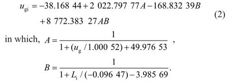
Since it is hard to form a continuous liquid sheet whereLi<1 mm, with the influence of liquid flow on the average flow velocity of the liquid sheet being ignored, the average flow velocity of the liquid sheet atLi=1~9 mm can be expressed as:
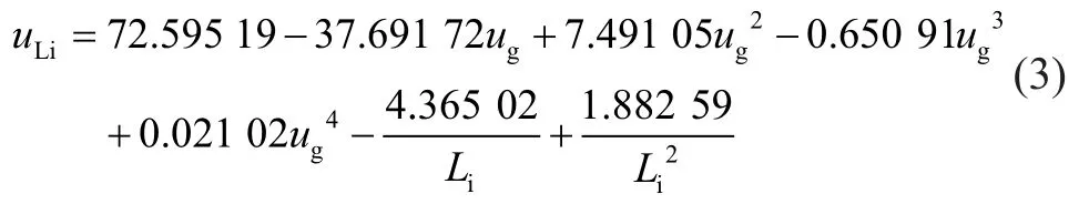
The average relative error of formulas (2) and (3) is 1.3% and 3.7%, respectively. The velocity difference between gas and liquid is:
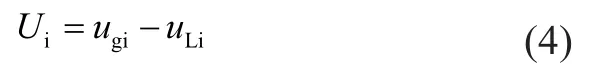
If the relationship between the angle coordinate parameterjand location parameter on spray-holecan be written as:
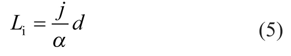
wheredis the diameter of spray-hole. Therefore, the average flow velocity of the liquid sheet within the range of between (j-5)°-j° can be obtained through transformation of coordinates, and at this time, the gas-liquid relative velocity is:
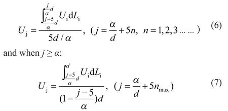
Substitution of formulas (2) – (5) for formulas (6) and (7) results in:
When the liquid sheet is broken into the form of long wave, the viscosity can be ignored. Judging from formulas (1) and (5), the wave length of the corresponding most unstable wave can be obtained at the moment when the liquid sheet breaks down into droplets as shown below:
According to the idealized model of Dombrowski[11], the breaking of liquid sheet can produce a cylindrical liquid silk first, the diameter of which is:
It is supposed that the liquid sheet is distributed with a uniform thickness on the spray-hole, namely,Whenthe liquid sheet thicknesshis obtained by liquid flow and the average flow velocity of the liquid sheet is:
By combining formulas (3), (15) and (16) one can obtain:

After the liquid sheet is broken down into liquid silk, under the effect of unstable wave the liquid silk will be broken down to droplets when the wave amplitude is equal to the radius of liquid silk. The diameter is:
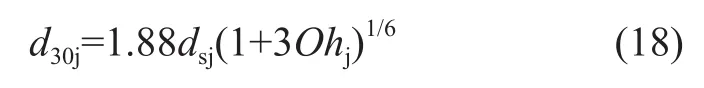
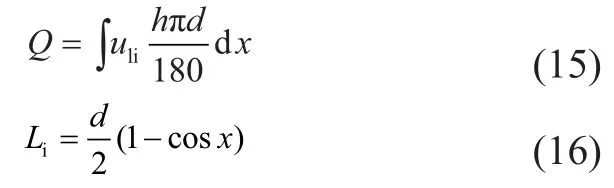
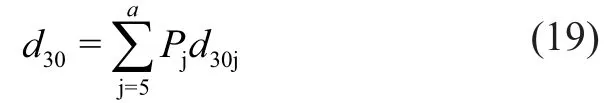
Formula (18) is the average droplet diameter within the angle ofj. The overall average diameter of drop generated from spray-hole is:
4.2 Model test
By substituting the operating conditions into formulas (2) to (19), the average size of CTST drop can be worked out. Figure 9 demonstrates the comparison of the theoretical and experimental results, where the average relative error is 8.7% and the maximum relative error is not greater than 15%. The results showed that the average droplet size decreases obviously with an increasing gas velocity; and the average size of droplet increases slightly with increase in liquid flow. Under experimental circumstances, the average drop size is around 1.0 mm to 2.5 mm. However, as shown in Figure 9, the theoretical trend is different from the experimental trend; especially when the range ofugis between 6 m/s and 7 m/s, which is formed due to the change of the liquid flow volume passing through the spray hole caused by the change of gas velocity.
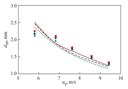
Figure 9 Comparison of d30between the theoretical and experimental results
5 Conclusions
(1) Gas velocity passing through the hole is a key factor affecting the spray angle and increases gradually with increase in the gas velocity. When the gas velocity exceeds 7.5 m/s, the spray angle becomes stable at around 55°. The average flow velocity of the liquid sheet at the spray-hole increases with an increasing gas velocity, and decreases slightly with the increase in the liquid flow rate; moreover, it increases from the bottom of spray-hole to the top. The density of drops distribution at the spray area can be described by the Rosin-Rammler function with the liquid drops concentrated in the area of the spray angle between 20° to 40°, and it gradually becomes uniform with an increase in the gas velocity and flow rate of the liquid.
(2) A theoretical model of the average droplet size was established according to the unstable wave theory. The experimental and theoretical results demonstrate that the average drop size deceases with an increasing gas velocity, and increases slightly with the increase in the liquid flow rate. In the normal working range, the average drop size is about 1.0 mm to 2.5 mm.
Acknowledgement:This work was supported by the Science and Technology Research and Development Plan of Hebei Province, China (12276710D).
Symbol Description
d—Diameter of spray-hole, m
h—Liquid sheet thickness, m
j—Interval parameter of angle, (°)
k—Number of unstable wave when liquid sheet breaks, m-1
Oh—Ohnesorge value
P—Distribution density, %
Q—Liquid flowrate, m3/s
U—Gas-liquid relative velocity, m/s
x—Central angle, (°)
α—Spray angle, (°)
v—Kinematic viscosity, m2/s
ρ—Density, kg/m
σ—Coef ficient of surface tension, N·m
Subscript
g—Gas
L—Liquid
i—Corresponding to location parameterLi
j—Corresponding to angle parameterj
[1] Liu J D, Lu J H, Zhang J P, et al. Combined trapezoid spray tray and its hydromechanics [J]. Journal of Chemical Industry and Engineering, 2005, 56(6): 1144-1149
[2] Wang Z Y, Liu Q D, Liu J D, et al. Spatial concentration distribution of combined trapezoid spray tray [J]. Journal of Tianjin University, 2010, 43(3): 277-282 (in Chinese)
[3] Nonnenmacher S, Piesche M. Design of hollow cone pressure swirl nozzles to atomize Newtonian fluids [J]. Chemical Engineering Science, 2000, 55(19): 4339-4348
[4] Negeed R, E-S, Hidaka S, Takata Y. Experimental and analytical investigation of liquid sheet breakup characteristics [J]. International Journal of Heat and Fluid Flow, 2011, 32 (1): 95-106
[5] Zhang M C, Lu Y, Wang J Y, et al. Mathematical modeling on the gas-liquid two phase flow in the Y-jet nozzle and its atomization process [J]. Combustion Science and Technology, 2003, 9(2): 153-156
[6] Zhou Y G, Zhang M C, Yu J, et al. Experimental investigation and model improvement on the atomization performance of single-hole Y-jet nozzle with high liquid flow rate [J]. Power Technology, 2010, 199(3): 249-255
[7] Crapper G D, Dombroswki N, Pyott G A D. Kelvin-Helmholtz wave growth on cylindrical sheets [J]. Journal of Fluid Mechanics, 1975, 68(3): 497-502
[8] Yang L J, Xu B R, Fu Q F. Linear instability analysis of planar non-Newtonian liquid sheets in two gas streams of unequal velocities [J]. Journal of Non-Newtonian Fluid Mechanics, 2012, 167(1): 50-58
[9] Liu K, Sun D J, Yin X Y. Instability of gas/liquid coaxial jet [J]. Journal of Hydrodynamics, 2007, 19(5): 542-550
[10] Meyer J, Weihs D. Capillary instability of an annular liquid jet [J]. Journal of Fluid Mechanics, 1987, 179(6): 531-545
[11] Dombrowski N, Johns W R. The aerodynamic instability and disintegration of viscous liquid sheets [J]. Chemical Engineering Science, 1963, 18(7): 203-214
[12] Senecal P K, Schmidt D P, Nouar I, et al. Modeling highspeed viscous liquid sheet atomization [J]. International Journal of Multiphase Flow, 1999, 25(6/7): 1073-1097
[13] Liu J D, Li C L, Wang Z Y, et al. Mathematical model of liquid quantity elevated on combined trapezoid spray tray [J]. Journal of Chemical Engineering of Chinese Universities, 2007, 21(1):163-167 (in Chinese)
[14] Liu J D. Study on gas-liquid two phase flow and mass transfer in the cap of combined trapezoid spray tray [D]. Tianjin: Tianjin University, 2008 (in Chinese)
[15] Mugele R A, Evans H D. Droplet size distribution in sprays[J]. Industrial & Engineering Chemistry, 1951, 43(6):1317-1324
[16] Senecal P K, Schmidt D P, Nouar I, et al. Modeling highspeed viscous liquid sheet atomization [J]. International Journal of Multiphase Flow, 1999, 25: 1073-1097
Received date: 2014-01-24; Accepted date: 2014-05-18.
Prof. Li Chunli, Telephone: +86-22-60202246; E-mail: ctstlc@hebut. edu. cn.

- 中国炼油与石油化工的其它文章
- Preparation of Tungsten Film and Its Tribological Properties under Boundary Lubrication Conditions
- Effect of Stirring on Oil-Water Separation in Rare Earth Mixer-Settler
- Synergetic Effect of Y Zeolite and ZSM-5 Zeolite Ratios on Cracking, Oligomerization and Hydrogen Transfer Reactions
- Viscoelastic Characteristics of Asphalt Binders at Softening Point Temperature
- Solvothermal Synthesis of V2O3Catalysts for Oxidative Desulfurization of Dibenzothiophene
- Preparation of Spherical MgCl2/SiO2/THF-Supported Late-Transition Metal Catalysts for Ethylene Polymerization