Interval Uncertain Optimization of Vehicle Suspension for Ride Comfort
C.Jiang,S.Yu,H.C.Xieand B.C.Li
1 Introduction
Vehicle ride comfort is one of the main criteria for evaluating the performance of vehicles.Due to the uneven road excitation,changes in the engine torque,shaft unbalanced rotation and asymmetrical tire rotation,vibration will be caused during the driving of vehicles,which will result in passenger discomfort and cargo damage,and lead to wearing and fatigue damage of vehicle parts as well as lower the transport efficiency.Additionally,the vibration of vehicles is one of the major sources of interior vehicle noise.The intense vibration of vehicles may cause tires to bounce off the ground,affecting the power performance,braking performance,and handling stability of vehicles[Yu(2000)].The study of vehicle comfort optimization can improve the design parameters,enhance vehicle ride comfort,restrict the impact of vibration and shock on human bodies,and keep the cargo intact.Fruitful results have emerged from research in this field.Shi(2011)verified that the optimized matching of suspension system parameters is an important method for improving the vehicle ride comfort.Ni et al.(2006)obtained optimal comfort through the matching of suspension parameters for a type of passive suspension.Baumal et al.(1998)used the road-holding ability of the vehicle and the suspension working space as constraints and used the genetic algorithm to optimize the vehicle suspension system to obtain the minimum extreme acceleration of the passenger seat.Based on finite element analysis,Eriksson et al.(2000)used the stiffness and damping as design variables to improve the ride comfort of a city bus.Georgiou et al.(2007)optimized a 1/4 vehicle model with two degrees of freedom and obtained the optimal suspension stiffness and damping.Lu et al.(2007)established the multi-body dynamic model of vehicles and used the RMS of total acceleration as the evaluation criterion to optimize the system parameters of a leaf-spring bearing suspension.Naudé et al.(2003)established the two-dimensional multi-body dynamics for a vehicle and optimized the vehicle damper characteristics.Vilela et al.(2003)employed the virtual prototype technology to optimize the stiffness and damping parameters of a vehicle suspension system to improve the comfort.Jabeen(2013)applied the genetic algorithm to optimize the nonlinear suspension system under different road conditions.Sun et al.(2007)used the minimal pavement dynamic load as the design criterion and applied the genetic algorithm to optimize the system parameters of a truck’s passive suspension.
Most of the aforementioned studies on vehicle suspension comfort are based on considerable assumptions and simplifications,namely,presuming that all the key parameters(e.g.,stiffness,damping,road excitation,vehicle velocity,and mass)in the analysis of a vehicle suspension system can be given precise values.Consequently,the mechanical performance can be analyzed as a deterministic system,and the conventional deterministic method of optimization design can be applied to obtain a solution.However,in actual projects,due to the impact of manufacturing and measurement errors,and complex working conditions,many critical factors that affect the vehicle ride comfort are often associated with uncertainty;these factors include(but are not limited to)the sprung mass,tire stiffness,vehicle speed,and pavement roughness.Regarding these factors,a tiny deviation in a parameter might not cause considerable fluctuation in the suspension system performance,whereas the coupling of multiple parameters might result in considerable devia-tions in the suspension system performance;consequently,it seems difficult for the optimized design solution obtained under the deterministic assumption to satisfy the actual criterion of ride comfort design.Therefore,a thorough consideration of uncertainty in the vehicle suspension system and whereby the establishment of an uncertain optimization method for vehicle comfort are of important engineering significance to ensure the reliability and stability of vehicle comfort design as well as the overall performance of suspension.
Based on the interval analysis method,the present study formulates an uncertain optimization model and the corresponding solution algorithm for ride comfort of vehicles,which can effectively ensure the reliability and stability of vehicle comfort design.By using the interval analysis method,It is only required to obtain the lower and upper bounds of all the uncertain parameters that affect the ride comfort rather than their accurate probability distributions,which to some extent avoids the dependence of traditional probabilistic methods on a large number of samples and hence renders the uncertainty modeling and optimization design of a vehicle suspension system more convenient and efficient.The rest of this paper is organized as follows:section 2 introduces the basic theory of automobile vibration,section 3 establishes the optimization model of vehicle suspension for ride comfort,section 4 establishes the uncertain optimization model and the corresponding algorithm based on the interval analysis method,section 5 analyzes several examples,and section 6 concludes the work presented in this paper.
2 Basic theory of automobile vibration[Weaver et al.(1990);Sun et al.(2012);Yu and Lin(2005);Jin et al.(2002)]
According to actual conditions in engineering problems,the vehicle suspension system can be simplified as a multi-degree of freedom vibration model.Using the Newton method or Lagrange equation to implement the dynamic analysis of a suspension vibration model,the vibration differential equation can be established as follow:

whereare the displacement,velocity and acceleration vectors,respectively;Qis the excitation vector;Mis the mass matrix;Cis the damping matrix;Kis the stiffness matrix;andKtis the tire stiffness matrix.The dimensions of the above matrices and vectors are determined by the degree of freedom for the vehicle vibration model.
The aforementioned problem can be treated as a linear vibration system.During the comfort analysis,based on the pavement power spectral density and the frequency response function derived from the input vehicle suspension system parameters,the power spectral and standard deviation of individual vibration responses are obtained,which are used to analyze the influence of vibration system parameters on different physical quantities and to evaluate the ride comfort[Yu(2000)].
By implementing Fourier transform on both sides of the vibration differential equation,we can derive the frequency response function of the vibrating system,H(ω):

where ω is the circular frequency of vibration for the vehicle body,and elementHijon theithrow andjthcolumn in matrixH(ω)represents the frequency response function from the road input at thejthwheel to theithdegree of freedom of the vehicle system.
For the response point of theithdegree of freedom in the vibration model,the auto-spectral density of displacement responseGZi(ω),velocity power spectral densityG˙Zi(ω),and acceleration power spectral densityG¨Zi(ω)are:

whereHi(ω)is theithrow of the frequency response functionH(ω),Gq(ω)is the road power spectral matrix,‘∗’means conjugation of the matrix,and ‘T’means transposition of the matrix.
The vibration response with a random pavement input has the same probability of being positive or negative,and hence the average is approximately zero and the variance is equal to the mean square value.Therefore,the mean square value of the acceleration of the response point for theithdegree of freedom is:

where ω2and ω1are the upper and lower bounds of frequency,respectively.
If the vehicle vibration model hasNtires,the dynamic tire load on the road for thejthtire is:

wherekj,Zj,andqjare the stiffness,displacement,and road excitation of tirej.The frequency response function of the relative dynamic load of thejthtire to inputQis:

whereGjis the static load on tirej,n=1,...,N.
The dynamic load of the tire is also a Gaussian stochastic process with an average of zero,and thus,the mean square value of the relative dynamic load of thejthtire is:

The dynamic de fl ection of suspension above thejthtire is:

whereZxis the displacement corresponding to the joint of the vehicle body and suspension.The frequency response function of the suspension dynamic deflection above thejthtire to inputQis:

Therefore,the mean square value of the relative dynamic deflection of the suspension is:

3 Optimization modeling of vehicle suspension for ride comfort
3.1 Selection of the design variables
The suspension spring supports the weight of vehicle and can mitigate the impact of uneven pavements.The shock absorber damping mainly plays a role in suppressing the vibration.The larger the damping force,the faster the vibration disappears,whereas the elastic components that are connected with it in parallel would not fully play their roles.Meanwhile,the relatively large damping force might damage the connected parts and the vehicle frame.There is a contradictory relationship between impact mitigation and vibration suppression,which should be unified under the premise of normal operating conditions that ensure the safety of vehicles and passengers.This relationship is the basis for the design of matching between suspension spring stiffness and shock absorber damping.Therefore,in this study,we use suspension spring stiffness and shock absorber damping as the design variablesXof the optimization problem:

wherekrepresents the suspension spring stiffness vector,crepresents the linear damping vector of the shock absorber,and their dimensionpis related to the degrees of freedom of the vehicle vibration model.
3.2 Determination of the objective function
The method of evaluating the vehicle ride comfort is usually developed according to the response of the human body to vibration and the influence on maintaining the cargo integrity,and uses some physical quantities of vibration(e.g.,frequency,amplitude,and acceleration)as the evaluation criteria of ride comfort.The root mean square(RMS)of vehicle body acceleration is one of the commonly used criteria for evaluating the vehicle ride comfort.When the RMS of acceleration is relatively large,the passenger will feel uncomfortable and tired and may even experience adverse health effects[Yu(2000)].Therefore,under conditions in which spring stiffness and shock absorber damping can ensure the normal use of the suspension,the RMS of vehicle acceleration should be kept as small as possible so that the ride is comfortable.Therefore,in this study,we use the RMS of vehicle body acceleration for the center of mass as the objective functionf(X)for ride comfort optimization:

3.3 Establishment of the constraints
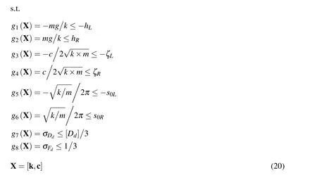
To ensure good ride comfort,the vehicle suspension must usually be relatively soft,and the static deflectionhis relatively large.However,hcannot be too large since the restriction of the suspension structural arrangement.Therefore,the stiffness constraint for suspension is:

wheremrepresents the equivalent suspension mass relative to springk,andhRandhLare the upper and lower design limits,respectively,of suspension static deflectionh.
The damping ratio ζ is usually employed to evaluate the decaying speed of vibration.If ζ is too large,it will transfer a relatively large road impact or even cause vehicles to bounce off the road surface and to lose the adhesive force;when ζ is relatively small,the sustaining period of vibration will become longer,which is not good for the ride comfort.Consequently,there is the following constraint:

wherecrepresents the shock absorber damping coefficient matched with springk,and ζRand ζLare the upper and lower bounds,respectively,of damping ratio ζ.
By decreasing the natural frequencys0,we can substantially decrease the vibrational acceleration of the vehicle,which is favorable for vehicle comfort.However,if the natural frequencys0is too low,the suspension dynamic deflectionDdincreases,and the probability of the suspension colliding with a bump stop increases,which is not good for ride comfort and operational reliability.Therefore,the natural frequencys0should satisfy the following relationship:

wheres0Rands0Lare the upper and lower bounds,respectively,of the natural frequencys0.
The suspension stroke[Dd]of the vehicle cannot be very large(due to the structural constraint)and is usually 7-9 cm.To ensure that the probability of suspension impact on a bump stop is at most 0.3%,the RMS of the suspension dynamic deflection σDjdshould satisfy the following equation[Yu(2000)]:

The relative dynamic load of the wheel significantly affects the vehicle safety.When the relative dynamic load of the wheel is greater than 1,the wheel might bounce off the road surface and lose the force of adhesion to the pavement,and the vehicle will lose the capability of driving,braking,and steering.To maintain the probability of wheels bouncing off the pavement at a value below 0.15%,the RMS of the relative dynamic tire load σFjdshould satisfy the following equation:

In summary,an optimization model of vehicle suspension for ride comfort can be formulated as:

4 Interval uncertain optimization
Due to the influence of manufacturing,measuring errors and ambient conditions,there are many uncertain factors that affect the vehicle ride comfort,such as the sprung mass,unsprung mass,tire stiffness,vehicle speed,pavement roughness,spring stiffness,and the shock absorber damping.The coupling of these uncertain parameters could cause considerable deviations of the suspension system performance and thus makes it difficult for the design under the deterministic assumption to satisfy the requirement of vehicle comfort design under actual conditions.In this paper,we mainly consider the uncertainty of four parameters(i.e.,sprung massm,tire stiffnesskt,vehicle speedv,and pavement roughnessGq)as they have critical effects on vehicle ride comfort;these parameters are expressed as the vectorU=[m,kt,v,Gq].For example,the sprung mass exhibits considerable fluctuations due to the influence of manufacturing error,the number of passengers,and the amount of cargo;the tire stiffness is also significantly affected by the tire pressure and temperature,which generally cannot be precisely quantified.Even for pavements with the same grade,the pavement roughness exhibits significant uncertainty caused by influences from construction conditions,years of service,and the environment.Due to the variations in the work environment,loading conditions,habits of the driving personnel,and material degradation,it is difficult to state that these parameters obey a certain type of probability distribution,and thus,they generally cannot be effectively processed using traditional probability-based uncertainty analysis method.However,it is relatively easy to obtain the variation interval for these parameters based on general experience and existing samples.For example,it is not difficult to determine the variation range of the sprung massmbased on no-load condition and extreme loading condition of the vehicle.Using aB-class road as another example,the geometric mean of the road roughness coefficientGqis 64×10−6m3,whereas its variation interval has been provided by the relevant national standards.Therefore,in this paper,we introduce the interval analysis method for conveniently and efficiently evaluating the uncertainty in key parameters of the suspension system,thereby providing a new approach for the uncertain optimization design of vehicle ride comfort.
Using the interval analysis method[Moore(1979);Ben and Elishakoff(1990);Qiu and Wang(2005);Gao et al.(2010)],we only need to know the upper and lower bounds of the uncertain parameterU=[m,kt,v,Gq]of the suspension system:

whereare the variation interval and the lower and upper bounds of the parameterare? the? midpoint and radius ofUi,respectively.The uncertainty level of intervalis defined as:

After applying the interval approach to process the uncertain parameters in the suspension system,the optimization problem of ride comfort in Eq.(20)can be converted to the following interval uncertain optimization problem:

whererepresents the allowable interval of theithconstraint.In practical design,the allowable limit of a constraint function is often not a specific value,and instead,it should have a transitional state.In many cases,the constraint limit is treated as an interval,which can well describe this transition state or fuzziness and thus renders the uncertain optimization model of ride comfort more reflective of actual situations.Notably,in our interval optimization,we can also directly provide precise values for the constraint limits according to the practical situation,which does not affect the solving procedure of the following interval optimization.
At present,the interval analysis and optimization method have been applied to several engineering fields[Li et al.(2011);Wu et al.(2014);Wu et al.(2013);Li et al.(2013);Li et al.(2013)].We adopted our previously developed interval optimization methods[Jiang et al.(2008);Jiang et al.(2008);Jiang et al.(2012);Zhao et al.(2010)]to solve the aforementioned problem.First,by optimizing the interval midpoint of the objective function,we can convert the interval objective functionf(X,U)to the following deterministic objective function:

wherefe(X)represents the midpoint value of the objective function interval at any pointX.fL(X)andfR(X)are the lower and upper bounds of the objective function,respectively,and they can be derived through optimization:

The possibility degree of the interval can be used to quantitatively describe the degree that one interval is greater or smaller than another interval.In our previous work[Jiang et al.(2012)],a reliability-based possibility degree of interval(RPDI)was proposed,which can perform the quantitative comparison between crossing intervals and completely separated intervals.Based on this RPDI model,the interval constraints in Eq.(23)can be converted to the following deterministic constraints:


Through the above treatments,Eq.(23)can be transformed to:

s.t.

Obviously,Eq.(28)is a traditional deterministic optimization problem and thus can be solved using conventional optimization methods,such as sequential quadratic programming(SQP).
5 Numerical example analysis and discussion
In this section,the interval optimization method of vehicle ride comfort proposed in this paper is applied to three common vehicle vibration models with two degrees of freedom,four degrees of freedom,and seven degrees of freedom.To reduce the vertical vibration of the vehicle under-frame,the simple vibration model with two degrees of freedom is predominantly used;the half-car model with four degrees of freedom can evaluate the impact of vehicle pitching vibration on ride comfort;the spatial model with seven degrees of freedom mainly considers the three degrees of freedom(i.e.,vertical,pitch,and roll)of the vehicle mass and the four vertical degrees of freedom for the mass of four wheels,which is relatively complicated and can fully describe the movement condition of the vehicle.
5.1 Vehicle vibration model with two degrees of freedom
The vehicle vibration model with two degrees of freedom is illustrated in Fig.1.The parameters of the suspension system are selected as follows:m1=40.5kg for unsprung mass,k=18000N/m for suspension spring stiffness,andc=1500N·s/m for shock absorber damping.
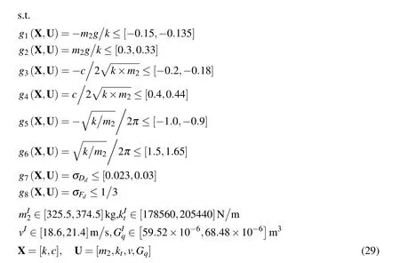
The uncertainty levels ε of the four interval parameters are all 7%,namely,mI2∈[325.5,374.5]kg for sprung mass,kIt∈[178560,205440]N/m for tire stiffness,vI∈[18.6,21.4]m/s for vehicle speed,andGIq∈[59.52×10−6,68.48×10−6]m3for the pavement roughness coefficient.The formulated interval optimization problem of ride comfort is as follows:

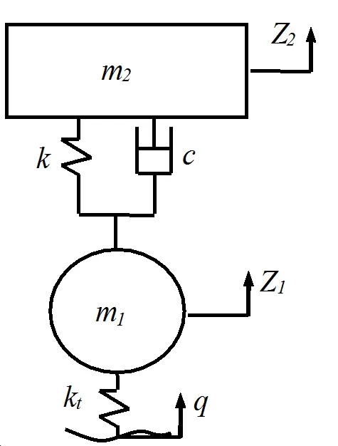
Figure 1:Vehicle vibration model with two degrees of freedom.
5.1.1Sensitivity analysis of the uncertain parameters
First,we analyze the effects of four uncertain parameters on the responses,such as the RMS of vehicle acceleration σ¨Z2,the RMS of suspension dynamic deflection σDd,and the RMS of the relative dynamic tire load σFd.Using the method proposed in[Yu(2000)],when we analyze the sensitivity of a certain parameter,we vary its value in the range within 50%of the midpoint value,and other parameters are fixed at the midpoint of the interval.We use the RMS of the vibration response for the midpoint value of the variables as the reference,and the gain is expressed in dB.Using the gain of the RMS of vehicle acceleration as the example,there is the following equation:

where σ¨Z2(uw)is the RMS of vehicle acceleration when the parameter to be analyzed takes the midpoint value,and σ¨Z2(ui)is the RMS of vehicle acceleration when the parameter takes other values.Using the same approach,we can derive the RMS of suspension dynamic deflection and the gain of the RMS of the relative dynamic tire load.
The influence of the pavement roughness coefficientGqon the RMS of the vibration response is depicted in Figure 2(a).Shown in this figure,as the pavement roughness varies,the variation curves for the RMS of vehicle accelerates,the RMS of suspension dynamic deflects,and the RMS of tire dynamic load completely overlaps with each other,and the three vibration responses are all extremely sensitive to the variation in the pavement roughness.The influence of vehicle speedvon the three vibration responses is shown in Figure 2(b).By comparing Figures 2(a)and 2(b),it is observed that the influences of the vehicle speed and pavement roughness on the three vibration responses are identical because both of them have a linear relationship with the power spectral density of pavement input and are not related to the frequency response function of the vibration system.The faster the speed,the higher the suspension vibration frequency;in addition,the shock and vibration on the vehicle and passengers would be more intense.The influence of the tire radial stiffnesskton the three vibration responses is presented in Figure 2(c).According to the curve shown in the figure,the variation of tire stiffness has a small influence on the suspension dynamic deflection.When the tire stiffness increases,the variation of the dynamic load between the wheels and pavement increases,and the grounding safety of the wheels worsens.The tire stiffness has a significant influence on the vehicle acceleration,and a soft tire helps to improve the ride comfort.The influence of the sprung massm2on the three vibration responses is displayed in Figure 2(d).We can observe that,as the sprung mass increases,the RMS of vehicle acceleration and the RMS of the relative dynamic tire load decreases,whereas the RMS of suspension dynamic deflection increases.The increase in sprung mass can effectively improve the ride comfort.In summary,the influences from the pavement roughness coefficient,vehicle speed,tire stiffness,and sprung mass on the ride comfort are relatively sensitive,and thus,it is crucial to consider the uncertainties of these parameters when studying the optimization of ride comfort.
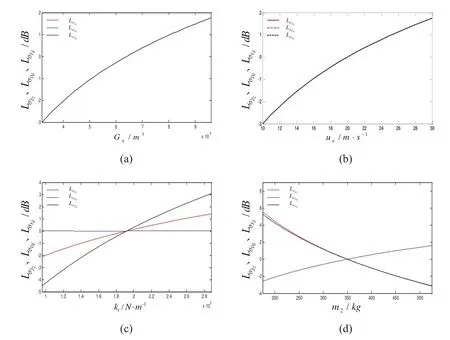
Figure 2:Effects of uncertain parameters on the RMS of the vehicle vibration responses.
5.1.2Results of the interval optimization
For convenience,we give the same RPDI level λ for all the interval constraints and consider the scenarios with different λ values in the range of 1.0-1.5.The optimization result of Eq.(29)is presented in Fig.3 and Table 1.
According to Fig.3,as λ increases,the upper and lower bounds and midpoint of the objective function all increase because a relatively high RPDI level means a more stringent restriction on the given interval constraints and thus results in a relatively small feasible region and a relatively poor value of the objective function.In addition,we find that,although the objective function interval generally exhibits an upward trend as λ increases,its interval width roughly remains constant because the uncertainty level of the parameters remains unchanged,whereas the variation interval of the objective function is mainly caused by the parameter uncertainty.
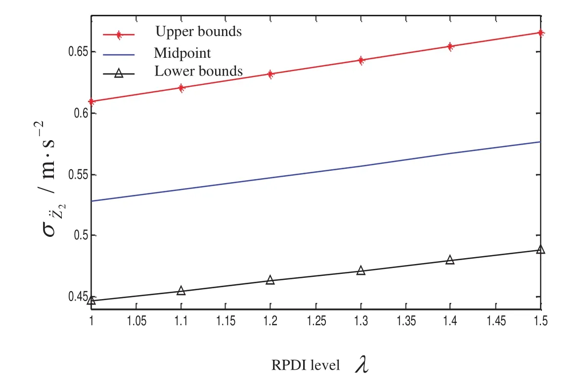
Figure 3:Variation curves of the interval optimization results of the vehicle vibration model with two degrees of freedom with respect to the RPDI level.
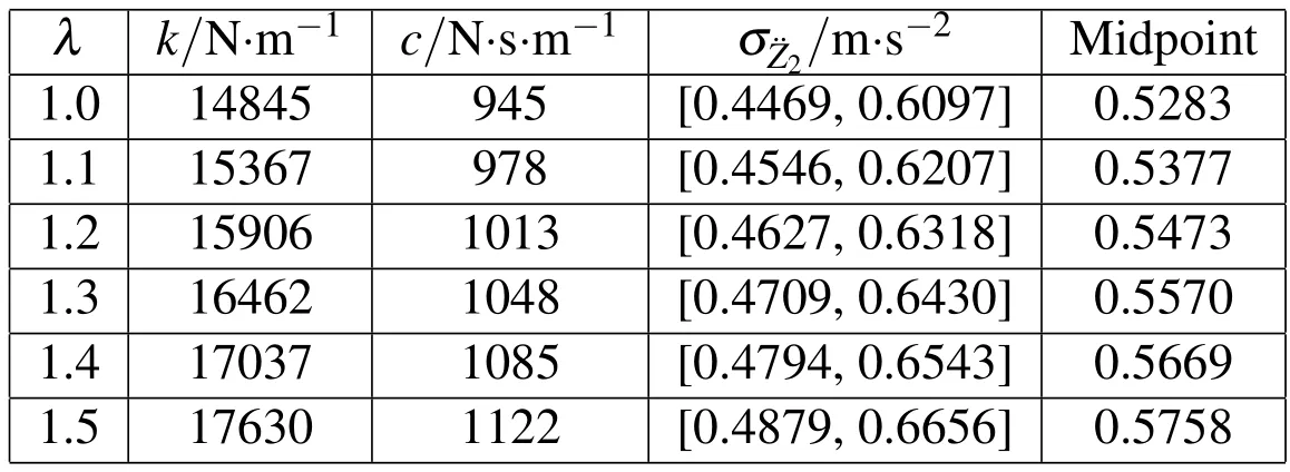
Table 1:Results of the interval optimization of vehicle ride comfort with two degrees of freedom for different RPDI levels.
According to Table 1,for λ=1,the optimal suspension design parameters arek=14845N/m andc=945N·s/m,and the objective function for the optimal design solution is σ¨z2=[0.4469,0.6097]m/s2,and inside this interval,the human body will experience some subjective discomfort.The intervals of individual constraints areg1(X,U)=[−0.2472,−0.2149]m,g2(X,U)=[0.2149,0.2472]m,g3(X,U)=[−0.2146,−0.2000],g4(X,U)=[0.2000,0.2146],g5(X,U)=[−1.0730,−1.0000]Hz,g6(X,U)=[1.0000,1.0730]Hz,g7(X,U)=[0.0064,0.0079]m,andg8(X,U)=[0.0941,0.1406].By comparing the limit values on the right side of the constraints in Eq.(29),we can observe that,under the optimal parameters of suspension design,the constraint variation caused by parameter uncertainty is strictly controlled in the required design range.
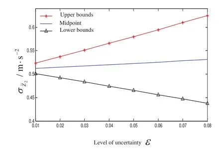
Figure 4:Variation curves of the interval optimization results of the vehicle vibration model with two degrees of freedom with respect to the uncertainty level.
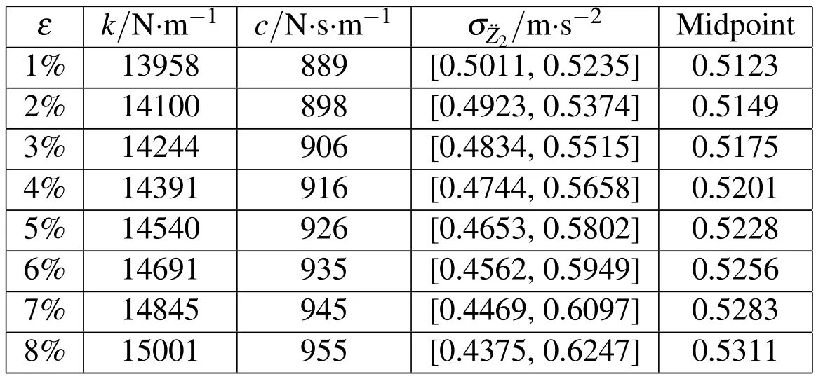
Table 2:Results of the interval optimization for the vehicle vibration model with two degrees of freedom for different parameter uncertainty levels.
In addition,we set the RPDI level to λ=1 and evaluate the situations with different parameter uncertainty levels in the range of 1%-8%.The results of interval optimization are shown in Fig.4 and Table 2.We can find that,as the parameter uncertainty level increases,the interval of the objective function(i.e.,the RMS of vehicle acceleration)for the optimal design widens because the relatively large parameter uncertainty will inevitably cause a relatively large response uncertainty;the midpoint of the objective function,namely,the average RMS of vehicle acceleration,slightly increases,while overall,it is relatively stable.Due to the increase in the interval width of the RMS of vehicle acceleration and the midpoint value,the increase in the parameter uncertainty level is not conducive to the design of vehicle ride comfort.Therefore,in the practical design of vehicle suspension,we should minimize the measurement and manufacturing error and attempt to control the uncertainty of some key parameters within a small range.
5.2 Vehicle vibration model with four degrees of freedom
The half-car vibration model with four degrees of freedom is depicted in Fig.5.The parameters of the suspension system are selected as follows:the masses of the front and rear tires arem1=40.5kg andm2=45.4kg,respectively;the moment of inertia of the vehicle around the pitch axis isIx=1222kg·m2;the distances from the front and rear axles to the center of vehicle mass area=1.25m andb=1.51m,respectively;k3andk4are the spring stiffness of the front and rear suspension,respectively;andc3andc4are the damping of the front and rear suspension,respectively.

Figure 5:Vehicle vibration model with four degrees of freedom.
The interval parameters aremI3∈[641.7,738.3]kg for sprung mass,kIt∈[178560,205440]N/m for tire stiffness,vI∈[18.6,21.4]m/s for vehicle speed,andGIq∈[59.52×10−6,64.48×10−6]m3for the coefficient of pavement roughness;all uncertainty levels ε are 7%.The formulated interval optimization problem for vehicle ride comfort is as follows:
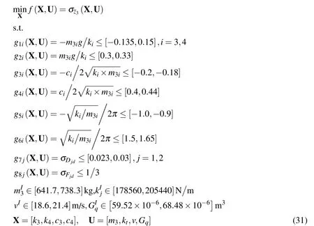
wherei=3,4 represents the front and rear suspensions,j=1,2 represents the front and rear wheels,m33=m3b?(a+b),andm34=m3a?(a+b).
We considered many different RPDI levels and performed the interval optimization of ride comfort.The optimization results are presented in Fig.6 and Table 3.
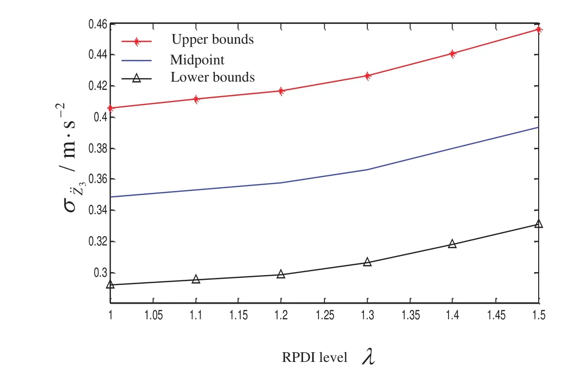
Figure 6:Variation curves of the interval optimization results of the vehicle vibration model with four degrees of freedom with respect to the RPDI level.
As shown in the figure,as λ increases,the upper and lower bounds and the midpoint of the objective function(i.e.,the RMS of the acceleration of the center of vehicle mass)all increase.In contrast with example 1,the variation here exhibits a certain nonlinearity.For λ=1,the parameters of optimal suspension design arek3=13195N/m,k4=16070N/m,c3=925N ·s/m,andc4=929N ·s/m.Under this design solution,because the variation range of the RMS of acceleration caused by the parameter uncertainty is σ¨Z3=[0.2917,0.4060]m/s2,the subjective feeling of the human body is comfortable,and the ride comfort is good.If we intend to add the reliability of constraint and set the RPDI level to λ=1.5,then the parameters of optimal suspension design arek3=17198N/m,k4=17558N/m,c3=1151N·s/m,andc4=1058N·s/m;under this design,the possible variation range of the RMS of acceleration is σ¨Z3=[0.3308,0.4566]m/s2.The subjective feeling of the human body will be slightly uncomfortable,and the ride comfort is reduced.
Similar to the vibration system with two degrees of freedom,we fix the RPDI level at λ=1 and evaluate the scenarios with different parameter uncertainty levels between 1%and 8%.The interval optimization results are presented in Fig.7 and Table 4.
Identical to the vibration system with two degrees of freedom,the interval of the objective function(i.e.,the RMS of the acceleration of the center of vehicle mass)under the optimal design solution widens as the parameter uncertainty level increases,whereas the midpoint slightly increases while remaining relatively stable.For ε=1%,the midpoint value of the RMS of acceleration is 0.3378m/s2;for ε=8%,the midpoint value is 0.3508m/s2,which is only 3.8%greater than the former value.
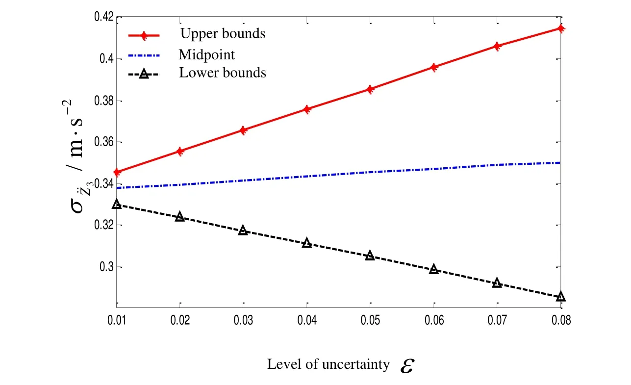
Figure 7:Variation curves of the interval optimization results of the vehicle vibration model with four degrees of freedom with respect to the uncertainty level.

Table 4:Results of the interval optimization for the vehicle vibration model with four degrees of freedom for different parameter uncertainty levels.
5.3 Vehicle vibration model with seven degrees of freedom
The vehicle vibration model with seven degrees of freedom is displayed in Fig.8.The suspension system parameters are selected as follows:the masses of the front and rear wheels arem1=40.5kg andm2=45.4kg,respectively;the moments of inertia of the vehicle around the pitch axis and roll axis areIx=2444kg·m2andIy=380kg·m2,respectively;the distances from the front and rear axles to the center of vehicle mass area=1.25m andb=1.51m,respectively;the tread isd=1.48m;k5andk6are the spring stiffness of the front and rear suspensions,respectively;andc5andc6are the damping of the front and rear suspensions,respectively.
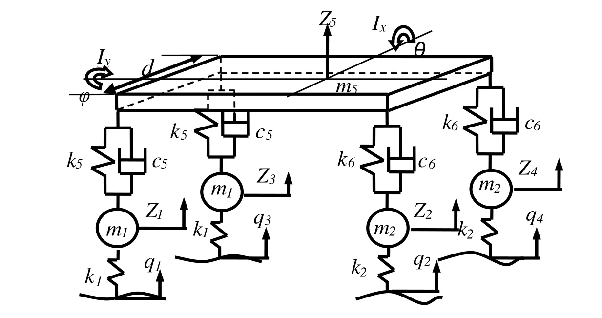
Figure 8:Vehicle vibration model with seven degrees of freedom.
The RMS of acceleration of the center of vehicle mass is the objective function,and the design parameters areX=[k5,k6,c5,c6].We used the sprung massm5,tire stiffnesskt,vehicle speedv,and pavement roughness coefficientGqas the interval parameters,all with an uncertainty level of 7%.The sprung mass ismI5∈[1283.4,1476.6]kg,the tire stiffness iskIt∈[178560,205440]N/m,the vehicles peed isvI∈[18.6,21.4]m/s,and the pavement roughness coefficient isGIq∈[59.52×10−6,64.48×10−6]m3.The formulated interval optimization problem of vehicle ride comfort is as follows:
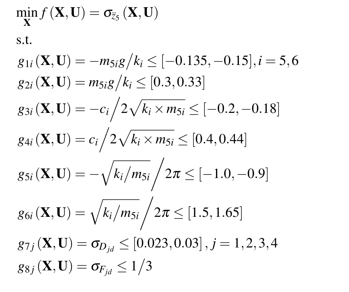

wherei=5,6 represents the front and rear suspensions,j=1,2,3,4 represents the four wheels,m55=m5b2(a+b),andm56=m5a2(a+b).
We still consider a variety of different RPDI levels,and the interval optimization results are presented in Fig.9 and Table 5.
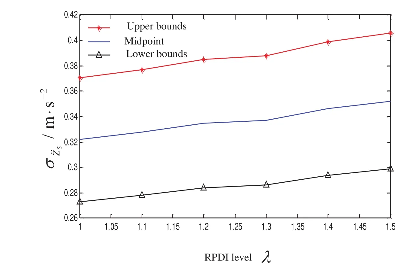
Figure 9:Variation curves of the interval optimization results of the vehicle vibration model with seven degrees of freedom with respect to the RPDI level.

Table 5:Results of the interval optimization of vehicle ride comfort with seven degrees of freedom for different RPDI levels.
According to the computational results,as λ increases,the objective function(i.e.,the upper and lower bound and midpoint of the RMS of the acceleration at the center of vehicle mass)also increases.For λ=1,the parameters of optimal suspension design arek5=14125N/m,k6=15140N/m,c5=1200N·s/m,andc6=902N·s/m.For this design solution,the variation range of the RMS of acceleration caused by the parameter uncertainty is σ¨Z5=[0.2732,0.3705]m/s2;therefore,the subjective feeling of the human body is relatively comfortable,and the ride comfort is good.If we increase the interval constraint reliability by increasing the RPDI level to λ=1.5,then the possible variation range of the RMS of the acceleration is σ¨Z5=[0.2988,0.4056]m/s2.Although the ride comfort is lower than that of λ=1,it still meets the requirement of practical comfort design.
6 Conclusions
By introducing the interval analysis method,an uncertain optimization model of vehicle suspension for ride comfort is formulated,which can improve the reliability of vehicle design and stability of vehicle riding.It is only necessary to obtain the upper and lower bounds of all uncertain parameters that affect the vehicle ride comfort,rather than their precise probability distributions.Thus we can to some degree avoid the relatively stronger dependence of traditional probabilistic methods on a large number of samples and renders the uncertainty modeling and optimization design of vehicle ride comfort more convenient and efficient.The method in this paper is applied to three typical vehicle suspension vibration models with two degrees of freedom,four degrees of freedom,and seven degrees of freedom.The computational results indicate that the optimal suspension design parameters can be obtained through interval optimization,which can control the variation interval of the constraint within the range of design requirements under an uncertain environment,thereby ensuring the reliability of the constraints while improving the objective for ride comfort.By increasing the reliability-based possibility degree of interval level,we can increase the reliability of constraints,but this treatment could also decrease the vehicle ride comfort.Therefore,it is necessary to provide a reasonable reliability-based possibility degree of interval level of constraints in the practical design of vehicle ride comfort.
Acknowledgement:This work is supported by the National Science Foundation for Excellent Young Scholars(51222502),the National Science Foundation of China(11172096),the program for Century Excellent Talents in University(NCET-11-0124)and the Fok Ying-Tong Education Foundation,China(131005).
Baumal,A.E.;McPhee,J.J.;Calamai,P.H.(1998):Application of genetic algorithms to the design optimization of an active vehicle suspension system.Computer methods in applied mechanics and engineering,vol.163,pp.87-94.
Ben-Haim,Y.;Elishakoff,I.(1990):Convex models of uncertainties in applied mechanics.Elsevier Science Publisher:Amsterdam.
Eriksson,P.;Friberg,O.(2000):Ride comfort optimization of a city bus.Structural and multidisciplinary optimization,vol.20,pp.67-75
Gao,W.;Song,C.M.;Tin-Loi,F.(2010):Probabilistic interval analysis for structures with uncertainty.Structural Safety,vol.32,pp.191-199.
Georgiou,G.;Verros,G.;Natsiavas,S.(2007):Multi-objective optimization of quarter-car models with a passive or semi-active suspension system.Vehicle System Dynamics,vol.45,pp.77-92.
Jabeen,S.D.(2013):Vibration optimization of a passive suspension system via genetic algorithm.International Journal of Modeling,Simulation,and Scienti fi c Computing,vol.4
Jiang,C.;Han,X.;Li,D.(2012):A new interval comparison relation and application in interval number programming for uncertain problems.CMC-Computers Materials&Continua,vol.27,pp.275-303.
Jiang,C.;Han,X.;Liu,G.R.(2008):A nonlinear interval number programming method for uncertain optimization problems.European Journal of Operational Research,vol.188,pp.1-13.
Jiang,C.;Han,X.;Liu,G.P.(2008):A sequential nonlinear interval number programming method for uncertain structures.Computer Methods in Applied Mechanics and Engineering,vol.197,pp.4250-4265.
Jin,X.X.;Zhang,L.J.;Jiang H.(2002):Automobile vibration analysis.Tongji University Press,Shanghai
Li,F.;Luo,Z.;Rong,J.et al.(2013):A Non-probabilistic Reliability-based Optimization of Structures Using Convex Models.CMES:Computer Modeling in Engineering&Sciences,vol.95,pp.453-482.
Li,F.;Luo,Z.;Sun,G.(2011):Reliability-based multi objective design optimization under interval uncertainty.CMES:Computer Modeling in Engineering and Sciences,vol.74,pp.39-64.
Li,S.;Zhao,F.;Ni,Q.J.(2013):Multi objective Optimization for Ship Hull Form Design Using SBD Technique.CMES:Computer Modeling in Engineering&Sciences,vol.92,pp.123-149.
Lu,J.W.;Chen,J.;Wang,Q.D.(2007):Optimization of Leaf-spring Suspension Parameters Based on Ride Comfort Simulation.Journal of System Simulation,vol.19,pp.5025-5029.
Moore,R.E.(1979):Methods and Applications of Interval Analysis.Prentice-Hall,Inc.,London.
Naudé,A.F.;Snyman,J.A.(2003):Optimisation of road vehicle passive suspension systems Part 2.Qualification and case study.Applied Mathematical Modelling,vol.27,pp.263-274.
Ni,J.S.;Ruan,M.Q.(2006):Optimization and Simulation of the Vehicle Comfort.Modern Machinery,vol.2,pp.8-10.
Qiu,Z.P.;Wang,X.J.(2005):Parameter perturbation method for dynamic responses of structures with uncertain-but-bounded parameters based on interval analysis.International journal of solids and structures,vol.42,pp.4958-4970.
Shi,J.P.(2011):Vehicle Ride Comfort Based on Matching Suspension System.Chinese Journal of Mechanical Engineering,vol.24,pp.271-276.
Sun,L.;Cai,X.;Yang,J.(2007):Genetic algorithm-based optimum vehicle suspension design using minimum dynamic pavement load as a design criterion.Journal of Sound and Vibration,vol.301,pp.18-27.
Sun,X.M.;Chu,Y.;Fan,J.et al(2012):Research of simulation on the effect of suspension damping on vehicle ride.Energy Procedia,vol.17,pp.145-151.
Vilela,D.;Tamai,E.H.(2003):Ride Comfort Suspension Optimization with Simulation Tools.In Modelling,Identification and Control,pp.136-140.
Weaver,Jr W.;Timoshenko,S.P.;Young,D.H.(1990):Vibration problems in engineering.John Wiley&Sons,Inc.
Wu,J.;Luo,Z.;Zhang,Y.et al.(2014):An interval uncertain optimization method for vehicle suspensions using Chebyshev metamodels.Applied Mathematical Modelling,DOI:10.1016/j.apm
Wu,J.;Luo,Z.;Zhang,Y.et al.(2013):Interval uncertain method for multibody mechanical systems using Chebyshev inclusion functions.International Journal for Numerical Methods in Engineering,vol.95,pp.608-630.
Yu,F.;Lin,Y.(2005):Vehicle system dynamics.China Machine Press,Beijing.
Yu,Z.S.(2000):Elementary Vehicle Dynamics.China Machine Press,Beijing.
Zhao,Z.;Han,X.;Jiang,C.;Zhou,X.X.(2010):A nonlinear interval-based optimization method with local-densifying approximation technique.Structural and Multidisciplinary Optimization,vol.42,pp.559-573.

