Rapid Springback Compensation for Age Forming Based on Quasi Newton Method
XIONG Wei , GAN Zhong XIONG Shipeng and XIA Yushan
1 Department of Mechanical Engineering, Gulin University of Aerospace Technology, Guilin 541004, China
2 Key Laboratory of Contemporary Design and Integrated Manufacturing Technology of Ministry of Education,Northwestern Polytechnical University, Xi'an 710072, China
1 Introduction
As a key forming technology for sheet metals, age forming is particularly suitable to fabricate integrated panels, which usually constitute aircrafts’ aerodynamic configurations and main load-bearing structures[1].Springback after age forming is far outweigh that of common sheet metal forming, because the temperature and forming time, which are dictated by the requirement to produce an improvement in mechanical properties of the material, since the residual stress cannot be fully relaxed by the process[1]. Approaches by adjusting mold shape,therefore, are crucial in dealing with springback of age forming.
Since data in handbooks is usually based on analytic results for 2D formation, springback compensation for complex 2D shapes and 3D shapes has to be carried out by trial-and-error method, which consumes both time and money[2]. To reduce cost, KARAFILLIS, et al[3–5]introduced springforward method to compute die shapes. Design contours of parts are used as molds to simulate forming in the method and external forces on nodes of the parts that maintain their shapes are determined the simulation. Then,the external forces are applied on the nodes of initial unformed parts and let them to springforward. The resulting shape is treated as the next trial for the mold shape.However, the method lacks convergence when parts are asymmetric[6]. WAGONER, et al[6–7], proposed the“displacement adjustment (DA) method”, in which desired part contour is compared with that of simulated part shape with finite element software iteratively. The method gains mold contour in next iteration by directly superimposing compensation distance on the original mold contour in forming direction. However, as the calculation of compensation distance is not theoretically grounded, the method contains some experiential elements[8]. And since compensation is made only in the stamping directions,which is easy to realize but ignores the actual displacements of nodes in springback, its accuracy is negatively affected, so as its iterative efficiency. Therefore,many efforts have been made to reduce the number of iterations.
First, considering compensation directions, YANG, et al[2], proposed comprehensive compensation method based on DA. By assuming the difference of normal angle between the compensated die shape and the initial die shape equals to that between the target part shape and the springback shape for corresponding nodes, compensation directions, in which springback is compensated, for nodes are calculated. This method can deal with large rotation and displacement occurring in springback for automotive panel stamping using high strength steels. Other attempts have been made by HAN, et al[9]brought forward nearest element projecting method and directly projecting to decide compensation directions and magnitudes. And these methods were verified by multiple stretch mold modification calculation for aircraft skins. However,compared to DA, which only adjusting nodes in the stamping direction, compensations in other direction mean considerable extra work.
Another approach to improve DA’s performance is adopting compensation coefficient. LINGBEEK, et al[10],analytically studied simplified stretch bending and obtained compensation coefficient denoted by geometric parameters,which offers DA certain physical meaning. Though analytical computation based on comparison two forming processes, CHAI[11]concluded a simplified expression for compensation coefficient,However, for complex parts, the compensation coefficient is difficult to be decided analytically.
Third, initial mold contours for iterations has also been modified to accelerate springback compensation procedure.For instance, YANG, et al[12], presented a rapid mold compensation method, which considers springback angles in designing mold contour and applies it in devising molds for rubber bladder hydroforming. Rather than using parts’design contour as initial value for iteration, the method compares characters of parts with data in a processing database, and adding the compensation angles gained from comparison to mold contours. However, cumulating data in the processing database needs experiments, which is costly and time-consuming. Especially when an autoclave is involved, such as autoclave age forming, a single experiment costs considerable funds.
In the field of age forming, iterative springback compensation method that has been described in detail is DA. For example, HUANG, et al[13–14], ZHU[15]employed DA to design dies for thick blanks and integrated panels. To increase iteration process, TAN[16]proposed a mutant DA method. The basic idea of the method is adjusting compensation coefficient according to the deviation.However, the coefficients are merely an experiential summary of finite element calculations in the past. GAN, et al[17], combined DA and transfer function method by successively employing finite element simulation and physical experiments to reduce deviation of a panel to 0.5 mm. Theoretically, the later method can also be used in iterative springback compensation with finite element simulation. However, to construct the transfer function at least two mold contours that are close to the desired mold shape are needed. This is a bit too harsh.
This paper aims to propose a rapid iterative springback compensation method for mold contours based on quasi-Newton algorithm. And effect of mesh size on the method is also studied. It provides another approach to accelerate the iteration process of springback compensation.
2 Quasi Newton Method for Springback Compensation
2.1 Forming deviation calculation
2.1.1 Constitutive equations
Process of age forming contains various phenomena,including elastic deformation, plastic deformation and stress relaxation caused by viscosity, thus three material properties are set respectively. And linear hardening model has been chosen for elasto-plastic property:

where E is Young’s model, H is hardening coefficient, andyandyare yield stress and yield strain, respectively.
Creep model that is embedded in ABAQUS soft-ware is employed to represent viscosity:

where B, n and m are material constants relating to temperature. Another reason for using material model took by ABAQUS is that its probability of convergence is higher than that of UMAT subroutines.
2.1.2 Finite element modeling
Age forming process can be divided into three stages: (1)Loading. Parts are loaded on the top surface to fully contact mold contours. (2) Aging. The parts are held in place,heating and keeping their temperature for a certain time,and a portion of elastic deformation transform into plastic deformation. (3) Unloading. After aging, loads that are on the parts are removed and springback occurs in the parts.ABAQUS/Explicit and ABAQUS/Standard are commingled to perform finite element analysis. Totally,three steps are involved:
Step 1: Loading. A panel, which is 3D deformable body,and a mold, which is discrete rigid body, are defined respectively. As loading time is considerable short,viscosity of material is ignored. And only elasto-plastic model is defined for the panel. The finite element model is solved by ABAQUS/Explicit solver. Unified pressure is inflicted on upper surface of the panel, so that its lower surface can fully contact with the mold contour.
Step 2: Aging. Geometric model of the panel is established with exactly the same geometric configuration and partition as that is done in step 1. And the panel is endowed with elasto-plastic property and viscosity and meshed with exactly the same pattern as that in step 1, too.Computation results from step 1 are employed as predefined field for the panel. Nodes in the lower surface of the panel are fixed as boundary condition. The model is solved with ABAQUS/Standard solver.
Step 3: Unloading. Panel model is reconstructed in the exactly the same way and calculation results from step 2 are defined as predefined field. The analyzing steps for springback are defined. And once again ABAQUS/Standard solver is used to compute the model of springback without molds.
2.1.3 Registration
The contour of the panel after simulation is represented by a set of nodes in the lower surface of the panel. Spatial position of this node set is different from that of the node set expressing the panel’s design contour. Therefore,registration is necessary before working out deviation between the two contours. There are two steps in registration. The first one is initial registration, which reduces deviation between simulation node set and design contour so that accurate registration can be performed. The second one is accurate registration, which minimizes the deviation.
Moment principle axis method[18]is used in initial registration. First centers of mass are calculated for design node set and simulation node set. Then simulation node set is moved so that its center of mass is superposed with that of design node set. Coordinates of nodes in both sets are transferred to a local Cartesian coordinate system whose origin is center of mass of design node set. Finally, inertial tensors and principal axis of inertia are computed and rotation is made.
When accurate registration is carried on, it is treated as an optimizing problem that can be solved by simplex method0. The method, however, is a local optimization algorithm. Thus, registration may sink into local optima and its result may seriously depend on it initial value. Here,genetic algorithm is employed in accurate registration. And to improve its stability and probability of finding global optima, following settings are made. First, optimal individual in every generation is chosen and put into next generation without crossover and mutation; second,mutation rate is relatively large (0.5) and at least 400 generations of evolution must be conducted by program to accumulate enough beneficial mutation.
2.1.4 Deviation calculation
Assuming positions of mold contour and panel are approximately parallel to plane XOZ in finite element model. Mesh node coordinates of mold contour are abstracted from ABAQUS and projected into plane XOZ.Therefore, mold contour can be expressed by equationwhere Ω is projection region in plane XOZ.
The calculation process for deviation between panel’s design contour and its simulation contour is shown in Fig. 1.It is necessary that the panel’s design contour is imported into calculation program. And as design contours in aerospace industry are usually expressed with CATPart format of CATIA, to avoid developing interface program to read files with CATPart format, computation program extracts mesh node coordinates in the lower surface of the panel when analyzing step 2 is completed. These coordinates are fitted with B spline surface and function that represents panel’s design surface is obtained.

Fig. 1. Principle of deviation calculation
Modifying time keywords in the program mentioned above, mesh node coordinateson panel’s lower surface can also be abstracted as panel’s contour in kth iteration while step 3 is completed.
Let SDbe norm and moveto conduct registration.Node setof panel’s contour after registration can be gained. The nodes can be fitted with B spline surface so that panel contour after formingis obtained. Thus, for a certain pointin mold contour SM, age forming deviation can be worked out as.
2.2 Compensation method
For a certain panel, the process of calculation forming deviation can be generalized as follows: a set of coordinates yi,i=1,2,… ,n that describe mold contour is given in projection region Ω. And then the corresponding deviationis computed. This can be described by equations:
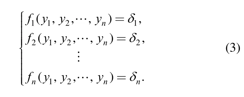
This function is called forming equation. Obviously,springback compensation tries to find a set ofwhich makei= 0,namely, solving equations:
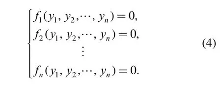
Through the analysis mentioned above, the problem of springback compensation is transformed into solving nonlinear equations, which can be worked out with Newton method.
Let us refer Eq. (4) as F ( y) = 0 for short. Very large amount of calculation forand its reverse matrix is needed, when basic Newton method is employed.Therefore, an approximate matrix Hkis considered to substitute, and H k+1 can be obtained by simply modifying Hk.
By Taylor expanding formula, following equations can be derived:

So choosing Hk1+, it makes the following equation even:

Let

then equation

can be referred as quasi Newton equation.
Assuming


since Hk1+evens Eq. (10), So


The algorithm can be described as follows:
(1) Set initial mold contour,permitted errorand initial Hessian matrix H0=I, k=0.
(4) Calculate

3 Numerical Simulations
Panels that are used in simulation validating have three typical contours, cylinder, sphere and saddle. Material for panels is 2124T851. Age forming temperature is 190oC and forming period is 4 h. Material parameters are taken from modified results in Ref. [19]. Internal structure of the part consists of eight ribs that intersect each other to form two“#” shapes. And the ribs’ height is 10 mm. Thickness of skins in their bottom is 2 mm. The panels’ length and width are 710 mm and 750 mm, respectively (Fig. 2). The compensation algorithm is carried out by developing a program with MATLAB.
Design contour for the cylinder panel has been chosen as a section of cylinder with radius 2000 mm. Fig. 3 shows computational results for cylinder panel. As iteration processes, deviation between simulation contour and design contour diminishes gradually. Maximum deviation declines from 20.05 mm to 0.618 4 mm after four compensation iterations. While Displacement adjustment method needs seven iterations to achieve a 0.740 8 mm deviation.
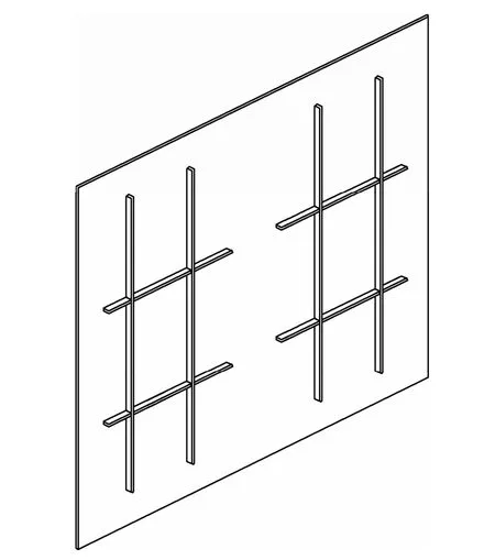
Fig. 2. Panel employed for simulation
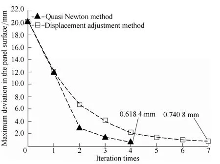
Fig. 3. Iterative compensation process for the panel with cylinder contour
Design contour for sphere panel has been selected as sphere with radius 2000 mm. Fig. 4 shows iteration process of the panel. Maximum deviation declines from 36.86 mm to 0.624 1 mm after five compensation iterations. While displacement adjustment method needs twenty-two iterations to achieve a 0.740 8 mm deviation.
Design contour for saddle panel bends in two opposite directions and both radius are 6000 mm. Fig. 5 shows iteration process for saddle panel. Maximum deviation declines from 6.068 mm to 0.3420 mm, after three iterations. While displacement adjustment method needs nine iterations to achieve a 0.7137 mm deviation.
4 Experiments
The panel used in experimental validating has a saddle shaped design contour with changing curvature. In Z direction, curvature radius changes from 1217.49 mm to 3061.11 mm in one end and from 1958.54 mm to 4556.14 mm in the other end. In X direction, curvature radius changes from 53 711.39 mm to 583158.87 mm. Its internal structure consists seven ribs that intersect each other forming six panes. And the ribs’ height is 7.5 mm.Thickness of skin in their bottom is 2.5 mm. The panel’s length and width are 400 mm and 380 mm, respectively(Fig. 6). Material and parameters for age forming is as same as described in the former section.

Fig. 4. Iterative compensation process for the panel with sphere contour
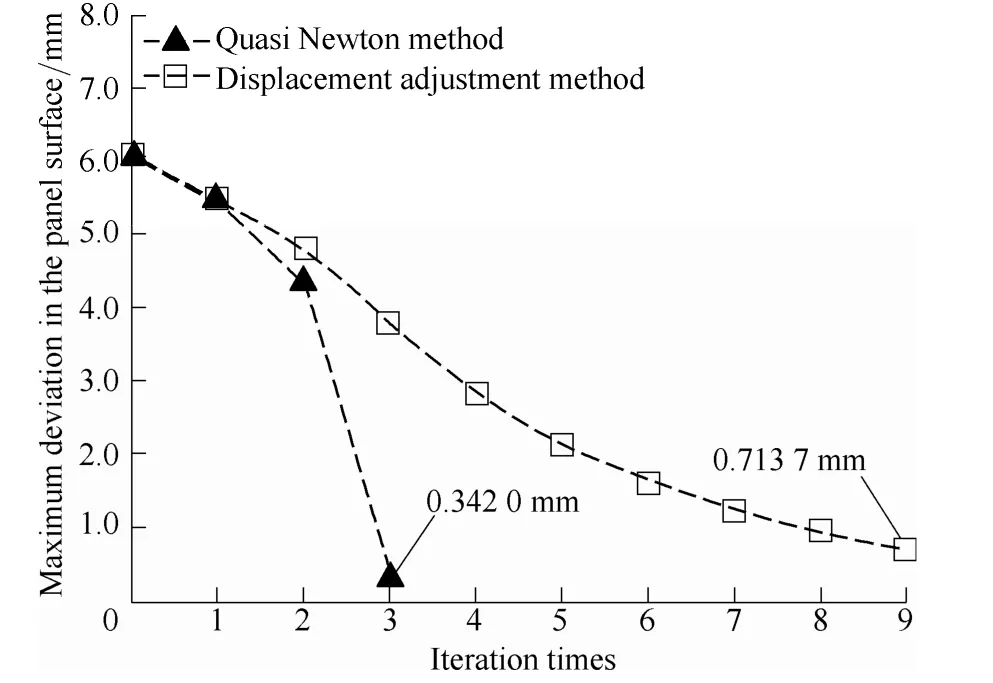
Fig. 5. Iterative compensation process for the panel with saddle contour

Fig. 6. Panel after forming
Finite element compensation for complex panel was carried out. After only two iterations, maximum deviation reduces to 0.4457 mm. And the mold was milled as the simulation results and age forming experiment was made in an autoclave.
3D digital measurement devise is used to measure the panel’s contour and results are compared with design surface with registration program described in section 2.1.3,which is slightly better than using Geomagic Qualify.Because the initial position for registration can be adjusted precisely. Fig. 7 illustrates the forming deviation which is less than 1mm. Thus, the compensation algorithm is feasible. Main cause that deviation in physical experiment is larger than that of simulation is simulation error in the finite element model, which concerns material model and material parameters. First, the classic creep model does not consider material parameter changes happening during age forming. Second, material parameters from Ref. [19] were obtained by back analyzing experimental results of T beam with 20 mm height ribs. There are structural difference between them and integrated panel employed in physical experiment.

Fig. 7. Forming deviation in Y direction
5 Discussions
Fig. 8 shows different iteration processes when various sizes of meshes in forming mold are used in the compensation. There is no obvious difference among them except slight deviation in calculating a certain mold contour’s forming error, which is mainly caused by the different mesh sizes. Because the deviation in a certain mesh node is worked out by computing the difference between two B-spline surfaces, which is gained by fitting nodes in the panel’s design and in its age forming one,respectively, as referred in section 2.1.4, employing different meshes means sampling the variation between the two B-spline surfaces in a different place. And if enough sampling points are taken, they can reflect the shape difference between the two surfaces, which is an objective existence. That is why mesh size has no apparent influence on iteration.
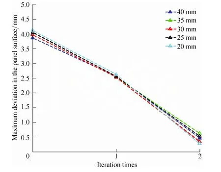
Fig. 8. Effects on mesh size for iteration
Through discussion mentioned above, springback compensation problem for mold contour has been treated as solving nonlinear equations numerically. The algorithm mentioned above is called rank 1 Quasi Newton method and there is more than one quasi Newton method. Other algorithms, such as Broyden-Fletcher-Shanmo rank 2 method can be useful in springback compensation. The procedure is as follows.
(1) Setting initial mold contour y(0), permitted errorand initial Hessian matrix H0=I, k=0;
This algorithm is employed to compensate mold contour for the complex panel in the former section and the calculation results are shown in Fig. 9. Similarly, maximum deviation in contour converges to 0.5725 mm after two iterations.
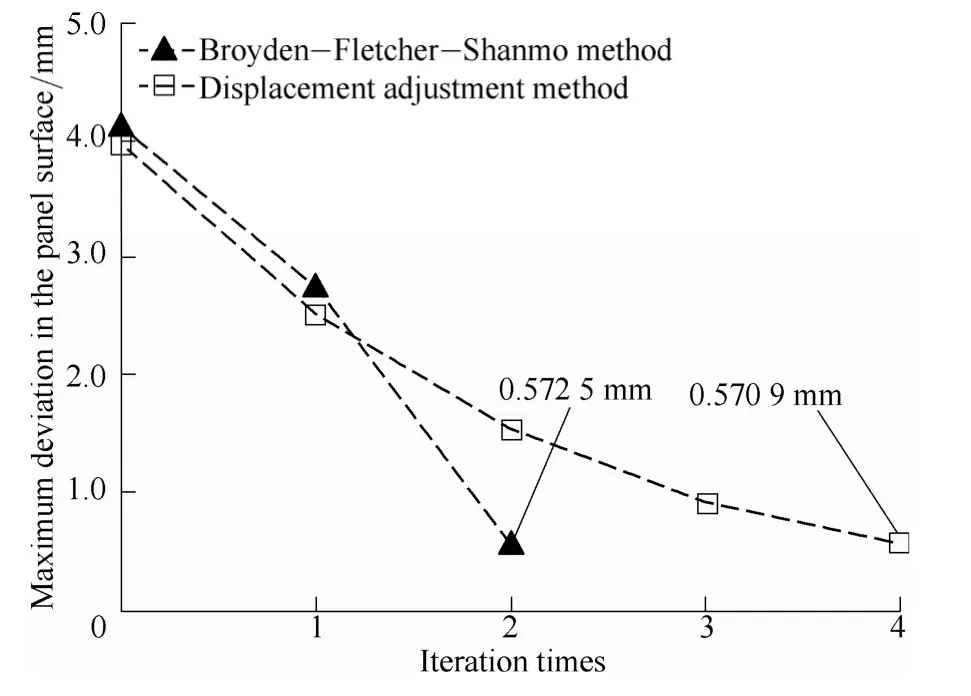
Fig. 9. Iterative process for the rank 2 method
6 Conclusions
(1) The process of calculation forming deviation for age forming with finite element software has been analyzed.And based on it the calculation process has been abstracted as solving nonlinear equations.
(2) Spingback compensation algorithm based on quasi Newton method is proposed. And case studies suggest the compensation algorithm has better accuracy and convergence rate than traditional displacement adjustment method. Furthermore, since the algorithm does not depend on any specific character of age forming, it has the potential to be used in other sheet metal forming process.
(3) Though nodes in meshes have been adjusted in the algorithm, meshes’ size has no obvious effect on compensation.
(4) A Broyden-Fletcher-Shanmo method, which is also based on the idea of solving nonlinear equations, is presented. Simulation shows its performance is better than displacement adjustment method.
[1] ZENG Yuansong, HUANG Xia, HUANG Shuo. The research situation and the developing tendency of creep age forming technology[J]. Journal of Plasticity Engineering, 2008, 15(3): 1–8.(in Chinese)
[2] YANG Xiang’an, RUAN Feng. A die design method for springback compensation based on displacement adjustment[J]. International Journal of Mechanical Sciences, 2011, 53(5): 399–406.
[3] KARAFILLIS A P, BOYCE M C. Tooling and binder design for sheet metal forming processes compensating springback error[J].Journal of Machine Tools and Manufacture, 1995, 36(4): 503–526.
[4] KARAFILLIS A P, BOYCE M C. Tooling design in sheet metal forming using springback calculations[J]. International Journal of Mechanical Sciences, 1992, 34(2): 113–131.
[5] KARAFILLIS A P, BOYCE M C. Tooling design accommodating springback errors[J]. Journal of Materials Processing Technology,1992, 32(1–2): 499–508.
[6] GAN Wei, WAGONER R H. Die design method for sheet springback[J]. International Journal of Mechanical Sciences, 2004,46(7): 1097–1113.
[7] GAN WEI, WAGONER R H, MAO Kunming, et al. Practical methods for the design of sheet formed components[J]. Journal of Engineering Materials and Technology, 2004, 126(4): 360–367.
[8] YANG Xiang’an, RUAN Feng. Analysis on springback compensation direction for die-face adjustment[J]. Journal of Plasticity Engineering, 2010, 17(2): 6–10. (in Chinese)
[9] HAN Jinquan, WAN Min, LI Weidong. Surface improvement based on springback compensation for aircraft skin stretching tool[J].Chinese Journal of Mechanical Engineering, 2009, 45(11): 184–188.(in Chinese)
[10] LINGBEEK R, HUETINK J, OHNIMUS S, et al. The development of a finite elements based springback compensation tool for sheet metal products[J]. Journal of Materials Processing Technology, 2005, 169(1): 115–125.
[11] CHAI Haixiao. Research for stamping springback control method based on compensation of geometry and process[D]. Hangzhou:Zhejiang University, 2006. (in Chinese)
[12] YANG Weijun, LI Dongsheng, LI Xiaoqiang, et al. Tool surface design method with rapid springback compensation for fluid-cell forming process[J]. Chinese Journal of Mechanical Engineering,2011, 47(12): 67–73. (in Chinese)
[13] HUANG Lin, WAN Min, WU Xiangdong, et al. Prediction of springback and tool surface modification technology for age forming of integral pane[J]. Chinese Journal of Aeronautics, 2009,30(8): 1531–1536. (in Chinese)
[14] HUANG Lin, WAN Min. Compensation algorithm for springback in age forming for aluminum alloy thick plate[J]. Chinese Journal of Aeronautics, 2008, 29(9): 1406–1410. (in Chinese)
[15] ZHU Jiazan. Age forming simulation and die design of integral panel of aluminum alloy[D]. Xi’an: Northwestern Polytechnical University, 2012. (in Chinese)
[16] TAN Haibing. Molded surface design research of the integral skin-panel based on aging forming[D]. Xi’an: Northwestern Polytechnical University, 2013. (in Chinese)
[17] GAN Zhong, XIONG Shipeng, ZHU Jiazan, et al. Structure of tool surface for age forming of integral panel of aluminum alloy[J].Chinese Journal of Mechanical Engineering, 2012, 48(16): 74–79.(in Chinese)
[18] LIU Jing. Review of registration based on CAD model[J]. Machine Tool & Hydraulics, 2007, 35(9): 231–232. (in Chinese)
[19] ZHANG Lei. Age forming simulation and springback prediction of aluminum alloy 2124[D]. Xi’an: Northwestern Polytechnical University, 2011. (in Chinese)
 Chinese Journal of Mechanical Engineering2014年3期
- Chinese Journal of Mechanical Engineering的其它文章
- A Task-oriented Modular and Agent-based Collaborative Design Mechanism for Distributed Product Development
- Analysis of the Flow Rate Characteristics of Valveless Piezoelectric Pump with Fractal-like Y-shape Branching Tubes
- Experimental Study of the Influence of Flow Passage Subtle Variation on Mixed-flow Pump Performance
- Numerical and Experimental Study on Flow-induced Noise at Blade-passing Frequency in Centrifugal Pumps
- Overall Life Cycle Comprehensive Assessment of Pneumatic and Electric Actuator
- Unsteady Flow Simulations in a Three-lobe Positive Displacement Blower
