
Experimental Study of the Influence of Flow Passage Subtle Variation on Mixed-flow Pump Performance
2014-03-01 01:48:34BINGHaoandCAOShuliang
BING Hao and CAO Shuliang
State Key Laboratory of Hydroscience and Engineering, Tsinghua University, Beijing 100084, China
1 Introduction
Mixed-flow pumps have the advantages of a wide application and a wide range of high efficiency operation,and are extensively used in industrial and agricultural production. In recent years, both international and domestic scholars have conducted a large quantity of researches on three-dimensional design method, performance prediction,model test and numerical simulation, impeller optimization design, and key parameters analysis.
GOTO, et al[1], established a computer-aided design system for pump impellers on the basis of 3D inverse design method, CAD modeling, automatic grid generation and computational fluid dynamic analysis. BING, et al[2],developed the direct and inverse iterative design method and accomplished 3D design of the mixed-flow pump impeller with programming. Yoon, et al[3], built the loss prediction model for the mixed-flow pump with consideration of separation loss and recirculation loss,based on the centrifugal compressor loss model. BING, et al[4], modeled the whole flow passage hydraulic loss and the volumetric loss for the mixed-flow pump, and utilized this model to analyse the generation and change mechanism of various internal losses inside the impeller of the mixed-flow pump.
ESCH, et al[5], analysed the effects of nonuniform suction velocity profiles on the mixed-flow pump performance by measuring the velocity distribution, the impeller torque and the force vector by experiments. OH, et al[6], employed CFD to predict the hydraulic performance and the cavitation performance and analysed the pump characteristics by considering the performance parameters such as the cavitation allowance. ESCH, et al[7], carried out the unsteady flow computation through the whole flow passage of the mixed-flow pump. Within the range from 70% to 130% of the best efficiency point flow rate, the computed values of the head agreed well with the experimental results. MUGGLI, et al[8], used CFD to proceed unsteady flow computation to the mixed-flow pump, and measured the pressure variation by allocating pressure sensors inside the pump casing to verify the numerical simulation results.
OH, et al[9], employed the mean streamline analysis to optimize the mixed-flow pump with the goal of minimizing the hydraulic loss, and analysed pump characteristics and flow details on the basis of comparison between the experimental and simulation results[10]. Taking the improvements of the head and the efficiency under the design flow rate as the goal, KIM, et al[11], selected the blade angle as the optimum parameter under the premise of fixing the shape of the meridional flow passage to optimize shapes of the impeller and the diffuser. The optimization eliminated the recirculation between the impeller and the diffuser and significantly improved the hydraulic performance. OH, et al[12], investigated the influence of blade stacking patterns on the impeller suction performance by simulating the cavitation flow in the mixed-flow pump.
Currently, researches on the influence of mixed-flow pump flow passage variation on pump performance mainly adopt the numerical simulation method. BONAIUTI, et al[13], analysed the influence of hub radius and other flow passage parameters on the mixed-flow pump hydraulic performance and cavitation performance by inverse design and numerical simulation. KIM, et al[14], predicted the mixed-flow pump hydraulic performance by numerical simulation, and discussed the influence of straight vane length ratio in the diffuser and the diffusion area ratio on hydraulic efficiency. BING, et al[15], selected the hub and shroud radius ratio of impeller and the outlet diffusion angle of outlet zone as the meridional flow passage parameters and analyzed the influences of various meridional flow passage parameters on the mixed-flow pump performance by numerical simulation.
In this paper, the inlet contraction flow passage of the mixed-flow pump was processed, and the influence of flow passage subtle variation on the mixed-flow pump hydraulic performance, pressure fluctuation and noise was analyzed with a series of important conclusions for mixed-flow pump flow passage optimization.
2 Test Device
Major parameters of the mixed-flow pump adopted in the model test are shown in Table 1. The structure of the test device is shown in Fig. 1. The hydraulic machinery test rig from Beifang Investigation, Design & Research Co. Ltd.was used to carry out the performance test. Fig. 2 shows the mixed-flow pump test rig, and key components such as the impeller, the diffuser, the inlet and outlet piezometric tubes,the motor, and the inlet tank.

Table 1. Major parameters of the mixed-flow pump

Fig. 1. Mixed-flow pump model test device structure

Fig. 2. Mixed-flow pump model test device structure
The measuring instruments and measuring error analysis of the mixed-flow pump hydraulic performance test can be found in Ref. [16]. To collect the pressure fluctuation data,high-accuracy pressure fluctuation sensors (Model:CGYL-201) were allocated on the mixed-flow pump impeller inlet in horizontal direction, on the diffuser outlet in horizontal direction and on the diffuser outlet in vertical direction, respectively (Fig. 3). This sensor had a measuring range of -10 m to 20 m water column, a dynamic response range of 0 to 1500 Hz. The pressure fluctuation test was conducted according to GB/T 17189-1997 Code for Field Measurement of Vibrations and Pulsation in Hydraulic Machines. The GO1 multifunctional USB advanced data collection and analysis system from Institute of Engineering Mechanics, China Earthquake Administration was used. The sampling frequency was 1024 Hz and the data collection lasted 20 s during the measuring process.

Fig. 3. Pressure fluctuation measuring point position
The blade angle under the design condition was defined as 0°. When the blade rotated from 0° to one side, if the impeller flow capacity increased, the blade angle was considered to be positive; if the opposite, the blade angle was negative. Fig. 4 shows the performance curves obtained by the mixed-flow pump model test with the blade angle as -6°.

Fig. 4. Performance curves of the mixed-flow pump with the blade angle as -6°
3 Inlet Flow Passage Variation
To analyze the influence of the flow passage variation on the mixed-flow pump performance, the end part of the inlet contraction flow passage of the mixed-flow pump (shown in Fig. 1, red box) was machined (shown in Fig. 5) with the maximum cutting depth of 5 mm. After this processing, the end part of the inlet contraction flow passage was cut from frustum cone surface to cylindrical surface with an increased minimum diameter of the inlet contraction flow passage.

Fig. 5. End part of the inlet contraction flow passage of the mixed-flow pump before (left) and after (right) processing
3.1 Influence on hydraulic performance
Fig. 6 shows the mixed-flow pump performance curves with different inlet flow passages with blade angle as -6°,where Qrdenotes the relative flow rate (defined as the ratio of actual flow rate Q to the best efficiency point flow rate QBEP).
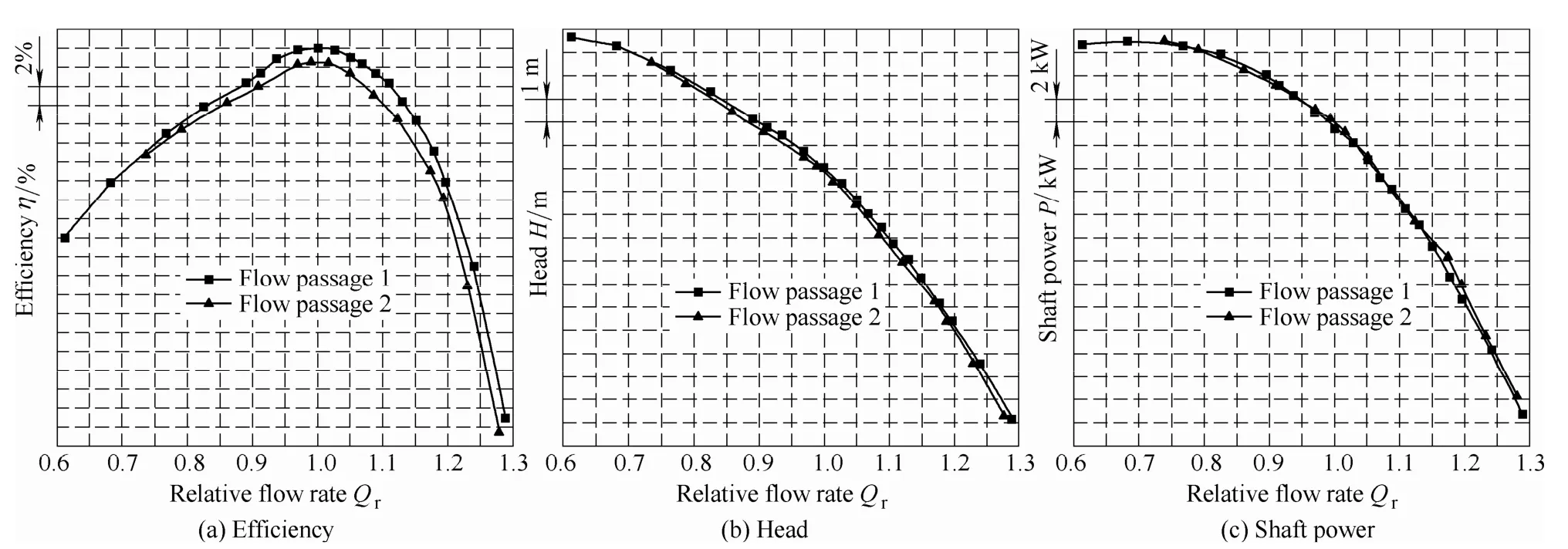
Fig. 6. Mixed-flow pump performance curves with different inlet flow passage
After the processing of inlet flow passage, the mixed-flow pump efficiency η had an obvious decrease(shown in Fig. 6(a)), especially the best efficiency which decreased by approximately 1.5%. But the flow rate at the best efficiency point did not vary significantly. With flow rate increasing, the decrement of η gradually increased.When Qrwas larger than 1.25, the decrement of η was more than 4%. Under the small flow rate condition,the variation of η before and after flow passage processing was relatively small compared to the variation at the best efficiency point.When Qrwas smaller than 0.75, the variation of η was less than 0.5%.
After inlet flow passage processing, the mixed-flow pump head H decreased (shown in Fig. 6(b)), suggesting a smaller working capacity of the mixed-flow pump impeller.The shaft power P increased mildly under the large flow rate condition, while decreased mildly under the small flow rate condition (shown in Fig. 6 (c)), and the variations were not significant.
Further analysis showed that a proper enlargement of the end part of the inlet contraction flow passage could lead to a smaller meridional velocity on the blade leading edge,thus changing the velocity triangle on the leading edge.When the blade shape and the blade angle remained fixed,the difference between the inlet flow angle and the blade angle on the leading edge would significantly increase,leading to a significant increase of incidence loss on the blade leading edge. The bigger the flow rate, the larger the incidence loss was. The rapid increase of the loss directly reduced the head and the efficiency of the mixed-flow pump.
By integrating the above analysis, it could be concluded that after processing the original flow passage, the variation of fluid velocity distribution led to an increase of internal flow loss of impeller, which significantly influenced the mixed-flow pump hydraulic performance.
3.2 Influence on pressure fluctuation
Fig. 7 and Fig. 8 show the time domain graphs of pressure fluctuations on the impeller inlet in horizontal direction or the diffuser outlet in horizontal direction before and after processing the mixed-flow pump inlet flow passage when blade angle is -6°, where relative head Hris the ratio of pressure head instantaneous value on the impeller inlet or the diffuser outlet to mixed-flow pump head under the same flow rate condition.
At the best efficiency point, pressure fluctuation amplitude was relatively small. Pressure fluctuation amplitude increased when deviating from the best efficiency point. The increase was especially significant with large flow rate condition. When Qr=1.23, pressure fluctuation amplitude was twice as much as the one at the best efficiency point.
After processing the inlet flow passage, at the same pressure fluctuation measuring point and with the same flow rate, the pressure fluctuation amplitude significantly increased. This suggested that changing the end part shape of the inlet flow passage would obviously reduce the stability of the mixed-flow pump internal flow. The processing depth of the inlet flow passage was subtle, but it had a significant influence on the flow stability.
Based on the above analysis of the time domain graphs,the relative value of the mixing amplitude was adopted to further analyse the characteristics of pressure fluctuation amplitude variation. Meanwhile, to avoid the influence of interfering signal on test accuracy during the test, the mixing amplitude was calculated by peak-to-peak value method with the confidence as 97%. The relative value A of the mixing amplitude was defined as the ratio of peak-to-peak value ΔH when confidence is 97% to the mixed-flow pump head H with the same flow rate condition:


Fig. 7. Time domain graphs of pressure fluctuations on the mixed-flow pump impeller inlet in horizontal direction

Fig. 8. Time domain graphs of pressure fluctuations on the mixed-flow pump diffuser outlet in horizontal direction
Fig. 9 shows the curves of the relative value A of mixing amplitude varying with flow rate. With the same flow passage, A gradually increased with flow rate increasing.Near the small flow rate condition and the design flow rate condition, the increases were gentle. However, near the large flow rate condition, A increased rapidly when the flow rate rised. This suggested that under the large flow rate condition, pressure fluctuation amplitude changed more rapidly with the flow rate changing. By comparing the values of A in different positions, it was noticed that the value of A on the diffuser outlet was nearly twice as much as the value of A on the impeller inlet. This was probably because of the interaction between the impeller and the diffuser. Meanwhile, the pressure fluctuation measuring point on the diffuser outlet was located on the turning of the flow passage and the change of flow direction also caused the increase of the pressure fluctuation. This demonstrated the influence of the sudden change of the mixed-flow pump flow passage shape in flow direction on the pressure fluctuation.

Fig. 9. Curves of pressure fluctuation relative amplitude varying with flow rate
After processing the inlet flow passage, the relative value A of the mixing amplitude significantly increased on both the impeller inlet and the diffuser outlet. This suggested that the increase of the inner diameter of the end part of the inlet contraction flow passage caused a more drastic pressure fluctuation with weaker operation stability of the mixed-flow pump. The increase of the pressure fluctuation amplitude was especially significant under the large flow rate condition.
3.3 Influence on noise
According to Methods of Measuring and Evaluating Noise of Pumps, the noise data of the mixed-flow pump under different flow rates before and after processing the flow passage were collected. Fig. 10 shows the curves of the average sound pressure level varying with the flow rate.The sound pressure level is defined as

where p denotes the sound pressure, p0is the standard sound pressure, which is 2´10–5Pa.

Fig. 10. Curves of average sound pressure level varying with flow rate
The two curves in Fig. 10 were cubic polynomial fitting curves which to some extent showed the trend of the average sound pressure level varying with the flow rate.After processing the flow passage, the noise significantly increased. This suggested that the mixed-flow pump internal flow was more disordered, and more energy was lost with noise.
4 Conclusions
By processing the mixed-flow pump inlet flow passage,the frustum cone surface of the end part of the contraction flow passage was made into cylindrical surface with a maximum processing depth of 5 mm. By testing the mixed-flow pump model under the same blade angle of-6° and different flow passages, the influence of the subtle variation of the flow passage on mixed-flow pump performance was analyzed to obtain the following conclusions.
(1) After processing the flow passage, the best efficiency of the mixed-flow pump decreased by approximately 1.5%.The decrease was significant under the large flow rate condition and relatively small under the small flow rate condition. Meanwhile, the mixed-flow pump head had an evident decrease, and the shaft power slightly increased under the large flow rate condition and slightly decreased under the small flow rate condition.
(2) After processing the flow passage, the pressure fluctuation amplitudes on the impeller inlet and the diffuser outlet both increased significantly. Pressure fluctuation was more violent, and the internal flow stability of the mixed-flow pump decreased. Meanwhile, the noise also significantly increased.
(3) The subtle variation (processing depth within 5 mm)led to a significant variation of the mixed-flow pump performance. Therefore, during the design process of the mixed-flow pump, a special attention should be paid to the flow passage optimization, as well as its coordinating relationship with the impeller and the diffuser of the mixed-flow pump.
[1] GOTO A, NOHMI M, SAKURAI T, et al. Hydrodynamic design system for pumps based on 3-D CAD, CFD, and inverse design method[J]. Journal of Fluids Engineering, Trans. of the ASME,2002, 124(2): 329−335.
[2] BING Hao, CAO Shuliang, TAN Lei. Iteration method of direct inverse problem of mixed-flow pump impeller design[J]. Journal of Drainage and Irrigation Machinery Engineering, 2011, 29(4):277−281. (in Chinese)
[3] YOON E S, OH H W, CHUNG M K, et al. Performance prediction of mixed-flow pumps[J]. Proc. Instn. Mech. Engrs., Part A: Journal of Power and Energy, 1998, 212(A2): 109−115.
[4] BING Hao, TAN Lei, CAO Shuliang, et al. Prediction method of impeller performance and analysis of loss mechanism for mixed-flow pump[J]. Science China Technological Sciences, 2012,55(7): 1988−1998.
[5] ESCH B P M V. Performance and radial loading of a mixed-flow pump under non-uniform suction flow[J]. Journal of Fluids Engineering, Trans. of the ASME, 2009, 131(5):051101-1−051101-7.
[6] OH H W, YOON E S. Hydrodynamically detailed performance analysis of a mixed-flow waterjet pump using computational fluid dynamics[J]. Proc. Instn Mech Engrs, Part C: Journal of Mechanical Engineering Science, 2008, 222(C9): 1861−1867.
[7] ESCH B P M V, KRUYT N P. Hydraulic performance of a mixed-flow pump: unsteady inviscid computations and loss models[J]. Journal of Fluids Engineering, Trans. of the ASME,2001, 123(2): 256−264.
[8] MUGGLI F A, HOLBEIN P, DUPONT P. CFD calculation of a mixed-flow pump characteristic from shutoff to maximum flow[J].Journal of Fluids Engineering, Trans. of the ASME, 2002, 124(3):798−802.
[9] OH H W, KIM K Y. Conceptual design optimization of mixed-flow pump impellers using mean streamline analysis[J]. Proc. Instn.Mech. Engrs., Part A: Journal of Power and Energy, 2001, 215(A1):133−138.
[10] OH H W, YOON E S, KIM K S, et al. A practical approach to the hydraulic design and performance analysis of a mixed-flow pump for marine waterjet propulsion[J]. Proc. Instn. Mech. Engrs., Part A:Journal of Power and Energy, 2003, 217(A6): 659–664.
[11] KIM S, CHOI Y S, LEE K Y. Design optimization of mixed-flow pump impellers and diffusers in a fixed meridional shape[C]//Proceedings of the 10th Asian International Conference on Fluid Machinery. Univ Teknologi Malaysia, Kuala Lumpur,Malaysia, 2009: 287−296.
[12] OH H W. Design parameter to improve the suction performance of mixed-flow pump impeller[J]. Proc. Instn. Mech. Engrs., Part A:Journal of Power and Energy, 2010, 224(A6): 881−887.
[13] BONAIUTI D, ZANGENEH M, AARTOJARVI R, et al.Parametric design of a waterjet pump by means of inverse design,CFD calculations and experimental analyses[J]. Journal of Fluids Engineering, Trans. of the ASME, 2010, 132(3): 031104-1−031104-15.
[14] KIM J H, AHN H J, KIM K Y. High-efficiency design of a mixed-flow pump[J]. Science China Technological Sciences, 2010,53(1): 24−27.
[15] BING Hao, CAO Shuliang, TAN Lei, et al. Effects of meridional flow passage shape on hydraulic performance of mixed-flow pump impellers. Chinese Journal of Mechanical Engineering, 2013, 26(3):469−475.
[16] BING Hao, CAO Shuliang, HE Chenglian, et al. Experimental study of the effect of blade tip clearance and blade angle error on the performance of mixed-flow pump[J]. Science China Technological Sciences, 2013, 56(2): 293−298.
 Chinese Journal of Mechanical Engineering2014年3期
- Chinese Journal of Mechanical Engineering的其它文章
- A Task-oriented Modular and Agent-based Collaborative Design Mechanism for Distributed Product Development
- Analysis of the Flow Rate Characteristics of Valveless Piezoelectric Pump with Fractal-like Y-shape Branching Tubes
- Numerical and Experimental Study on Flow-induced Noise at Blade-passing Frequency in Centrifugal Pumps
- Overall Life Cycle Comprehensive Assessment of Pneumatic and Electric Actuator
- Unsteady Flow Simulations in a Three-lobe Positive Displacement Blower
- Surface Roughness and Roundness of Bearing Raceway Machined by Floating Abrasive Polishing and Their Effects on Bearing’s Running Noise