Reduction of global effects on vehicles after IED detonations
V.DENEFELD*,N.HEIDERA.HOLZWARTH,A.SÄTTLER,M.SALK
aErnst-Mach-Institute,Eckerstr.4,79104 Freiburg,Germany
bErnst-Mach-Institute,Am Christianswuhr 2,79400 Kandern,Germany
1.Introduction
One of the most dangerous threats to military forces comes today from so called improvised explosive devices(IEDs)that detonate near operational vehicles.There exist many different types of IEDs.The threats range from hidden or buried explosives along the street to already elaborated explosively formed projectiles.There are the local effects like penetration and perforation of fragments and projectiles,but also the global effects connected with a high momentum transfer onto the vehicle and the subsequent severe acceleration effects on the vehicle occupants[1].
Originally the vehicle threat was mainly connected with the effects from shallowly buried military mines.Most interest was focused on the vehicle bottom structure and the deformations of the vehicle floor[2].Global effects and global accelerations for the occupants were not taken into account.The appearance of deeply buried IED charges changed the situation,and it was observed that this type of IED led to significantly higher global accelerations[3].Experimental set-ups were developed to measure and analyze the momentum transfer from buried charges onto simplified generic structures e.g.plates and cubes[4-6].These experiments were used to validate corresponding simulation models that were developed to analyze the detonation effects of IEDs on military vehicles.Of special interest in this context was a deeper understanding of the material behavior of geo-materials(sand,gravel)under the high loading conditions of IED detonation[7].Adequate material models were necessary to describe correctly the load transfer from the detonation to the vehicle floor[8,9].With these models,it was possible to precisely identify the material parameters that have the most influence on the momentum transfer and thus determine the global acceleration effects on the occupants[9].The applicability of Hybrid-III dummy models has already been shown in Ref.[10],where,e.g.,the lower leg injury criteria were analyzed,and the simulation results were compared to experimental data.
In this work,two concepts are analyzed,which can be used to reduce the global effects on vehicles.The approach is a combined method that uses numerical simulation and modeling as well as experimental tools for the analysis[11-13].The first concept concerns the vehicle shape and especially the V-shape of the vehicle hull[14].Experiments were performed with scaled vehicle models to determine the reduction effect of global loading due an optimized hull shape.Corresponding simulation models were validated with the scaled experiments.These simulation models could be used for the generation of full size vehicle models and the analyses of IED effects on vehicle occupants with the help of Hybrid-III dummy models.This allowed a detailed assessment of the functional principle of the second concept called DIC.Especially the combined effects of the IED detonation and the subsequent DIC on the vehicle occupants were examined in detail.Examples of the time development of selected injury criteria are presented(for example,dynamic response index(DRI),forces and moments[13]).
2.Scaled testing technology
A scaled testing technology is applied for the analysis of IED effects on the vehicles.The scaled model technology allows a significant reduction of vehicle size and related costs for the test arrangement.The vehicle under test and a typical test set-up for the analysis of geometry effects on the momentum transfer are shown in Fig.1.The global design parameters of the vehicle are 150 kg in mass,80 cm in length and 60 cm in height.The intention was to study global IED effects as momentum transfer,jump height and global acceleration.Therefore these physical parameters were determined during the experiment with the help of redundant measurement methods(high speed camera,accelerometer,and cable actuated position sensor).
3.Influence of vehicle geometry on momentum transfer
The influence of the vehicle shape was systematically studied in a combined experimental and numerical investigation.The effect of a V-shaped vehicle hull(with an angle of 25 ,see Fig.2)on momentum transfer was analyzed and compared with effect of a flat vehicle on momentum transfer.The scaled vehicles and simulation models are shown in Fig.2.The test conditions are that a high explosive(HE)is 200 g,is positioned under the centre of gravity of the vehicle and emplaced in sand,and its burial depth is 12.5 cm.The mass of all tested and simulated vehicles is kept constant for a better comparison.
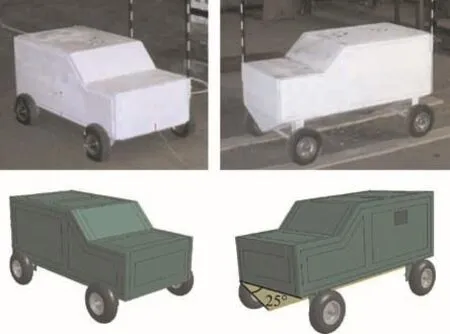
Fig.2.Scaled vehicles(top)and simulation vehicle models(bottom).Left:flat vehicles and right:V-shaped vehicles.
Simulations are executed with the finite-element software LS-DYNA.The vehicle is represented by a Lagrange model(30,000 shell elements),the embedding material with the HE charge and the surrounding air are represented by an Euler model(1.2 million solid elements).The detonation process is simulated with a complete Euler-Lagrange coupling method.Special attention must be addressed to the material modeling of the sand or gravel material.The model from Laine and Sandvik[7]for sand was used,which includes an equation of state for the compaction of loose sand particles and a Mohr-Coulomb type model for the strength behavior.
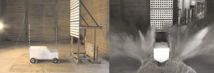
Fig.1.Test set-up for the scaled model technology with a V-shaped vehicle.
The definition of the ground clearance for V-shaped vehicles is not unambiguous.To a certain extent,it is an open question what situation has to be compared with the reference fl at vehicle.We therefore chose 3 different test set-up situations for comparison with the fl at vehicle(see Fig.3).Case A corresponds to the situation where the smallest distance between ground floor and vehicle is kept constant.A fair definition with respect to an equivalent distance between HE mass and vehicle floor is based on an average equal distance(Case B).Case C corresponds to a worst-case,where the vehicle is significantly nearer to the IED threat than that in the reference case.
Test results have been compared with the simulation.Fig.6 shows the jump heights of the different V-shaped vehicles compared to that of the flat vehicle.The agreement between simulation and experimental results is very good,with a maximum discrepancy of 9%.The applicability of the simulation models for the analysis of IED detonation processes has thus been proven.
Asymmetrical IED detonations have also been investigated with a flat vehicle and a V-shaped vehicle(Case B).The HE charge was placed under the front left wheel or under the left edge of the vehicle.For all types of vehicles,the loads were

Fig.3.Chosen test set-up configurations with different ground clearances of V-shaped vehicle.
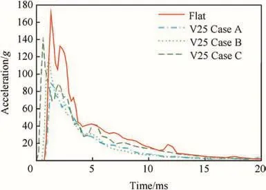
Fig.5.Global accelerations of flat and V-shaped vehicles after detonation.
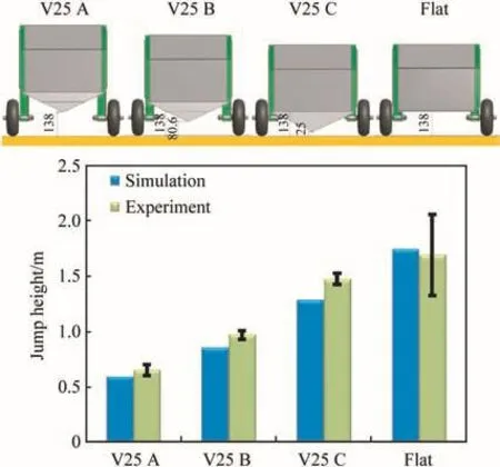
Fig.6.Jump height comparison between flat and V-shaped vehicles(simulation and experiment).
The corresponding simulation results for the momentum transfer onto the vehicle are summarized in Fig.4(velocity)and Fig.5(acceleration).The V-shaped vehicle floor leads to a significant reduction of the momentum transfer,between 15%and 47%,depending on the regarded case.A reduction of the global accelerations could be observed as well(especially the peak accelerations directly after the detonation are much smaller with a reduction being between 17%and 47%).clearly reduced for the asymmetrical detonations compared with the location of the HE charge under the center of the vehicle.For a location of HE under the wheel,the jump height(63 cm)of V-shaped vehicle was about 30%lower than that(86 cm)of the flat vehicle.For the case with the HE charge under the left edge of the vehicle,the jump height of V-shaped vehicle(38 cm)is similar to that(35 cm)of flat vehicle.The advantage of the V-shaped configuration is less pronounced if the HE charge is not direct below the tip of the V-shaped vehicle.This effect can be explained by the observation that,for the asymmetrical case,the detonation products are directed onto the vehicle bottom in a more perpendicular way.The deflection of the detonation products around the vehicle is therefore less effective for the asymmetric HE charge location.
It is worth noting that the V-shaped vehicle generally has a lower tendency to overturn.For the case with the HE charge being under the wheel,the flat vehicle was located on the roof after detonation(Fig.7),whereas the V-shaped vehicle came to stop lying on one side(Fig.8).An explanation of this phenomenon is given in Fig.9.For the V-shaped vehicle,the detonation products act more perpendicularly on the vehicle bottom,reducing the induced angular momentum and thus the tendency to overturn the vehicle in comparison with the flat vehicle.transfer from the underground detonation by a gun type system that ejects a corresponding mass and accelerates the vehicle in the opposite direction.With the help of simulation,the exact time profile of the vehicle loading can be determined.The counter measure must transfer a similar momentum with opposite direction onto the vehicle.A gun like system that accelerates a massive steel projectile for momentum compensation was chosen as ejection unit.The ejection system itself was designed with the help of the internal ballistics code IBHVG-2.The ejection unit mounted onto the scaled model vehicle is shown in Fig.10.The weight of the mounted ejection unit is 21 kg(13%of the total mass of the scaled vehicle).A significant reduction of the vehicle

Fig.7.Detonation under the front left wheel of the flat vehicle.

Fig.8.Detonation under the front left wheel of the V-shaped vehicle(Case B).
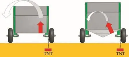
Fig.9.Effect of a buried charge detonation under the edge sides of the flat(left)and V-shaped(right)vehicles.The red arrow indicates the momentum transfer induced by the detonation,the white arrow indicates the propensity of the vehicle to overturn.
4.Concept of dynamic impulse compensation DIC
Another-and new-concept for reduction of global vehicle effects is based on the idea of compensating the momentum jump height of 70%can be achieved[11].The scaled model tests demonstrate the potential applicability of the DIC counter measure technology to reduce the momentum transferred onto the vehicle.
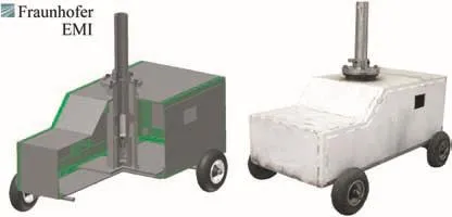
Fig.10.Scaled model test vehicle with DIC(ejection unit mounted on the vehicle).
5.Occupant loading reduction with dynamic impulse compensation
The purpose of the following study is to determine if the occupant loading can be reduced with DIC.We therefore modeled a generic full-scale vehicle with the DIC technology to simulate the occupant loading.
The generic vehicle is shown in Fig.11 and weighs about 20 tons.It is 7 m in length and 3 m in width and equipped with four ejection units which are placed at the four corners of the vehicle.This configuration would enable more flexibility,for example,for an asymmetric IED under a wheel.The ejection units could be triggered separately with a control unit in order to obtain a localized effect above the IED position.
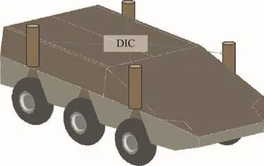
Fig.11.Generic full-scale vehicle model equipped with four DIC ejection units.
The simulation is done with LS-DYNA,using the validated sand model from the scaled vehicle simulations.A charge mass of 40 kg TNT was chosen,with a burial depth of 50 cm.An anthropometric test device(Hybrid III 50th percentile dummy model)is used and fastened to the seat with a 4-point belt(Fig.12(a)).The seat is attached to the side wall of the vehicle.
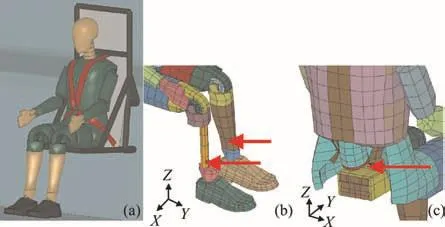
Fig.12.a)Hybrid III dummy model fastened with a 4-point seatbelt;b)Lower tibia load cells;and c)Pelvis accelerometers.
In order to quantify the occupant loading,the physical parameters which correlate well with the injury severity should be used.In case of IED detonation under a vehicle,the lumbar spine region and the lower legs are the body parts directly loaded by the shock and the global vehicle motion.Loads in other body parts,like in the head(head injury criterion or HIC,based on head acceleration),the neck(moment and compression force)and the thoracic(chest velocity)regions,are less critical in this case and will not be considered here for that reason.
We used the sensors placed on the dummy model to evaluate these loads.In the following,we used lower tibia load cells and pelvis accelerometers.The positions of the sensors are given in Fig.12(b)and(c).
The dynamic response index(DRI)is used as a criterion for injuries in the lumbar spine.It is calculated from the pelvic acceleration.A DRI value of 17.7 is linked with a 10%risk of significant injuries,such as inner organs laceration or contusion[15].This limit is therefore used by the NATO in the STANAG Standard AEP-55(Volume 2)as a pass/fail criterion for test vehicles[16].A tibia compression force of 5.4 kN is linked with a 10%risk of significant injuries,such as tibia or patella fractures[17].For that reason,this limit is used in the STANAG Standard.
The expansion of the detonation products around the vehicle and the formation of the crater in sand are presented in Fig.13(without DIC).The whole momentum is transferred on the vehicle within the first 40 ms after detonation.The vehicle shows then a free flight phase(maximum jump height of 1.7 m)and finally falls back on the ground after about 700 ms.The time sequence of the forces acting on the vehicle with DIC is given in Fig.14.The resulting force acting on the vehicle including the effect from DIC is reduced from 14 kN to 8 kN compared with the maximum global force from the detonation without DIC.The resulting jump height is given in Fig.15.It can be observed that the vehicle with DIC stays on the ground,compared to a jump height of 1.7 m for the reference case.The pelvic acceleration and the dynamic response index DRI are given in Figs.16 and 17,respectively.
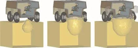
Fig.13.Simulation of an HE detonation under the generic full-scale vehicle model without DIC after 2 ms,10 ms and 20 ms(from left to right).
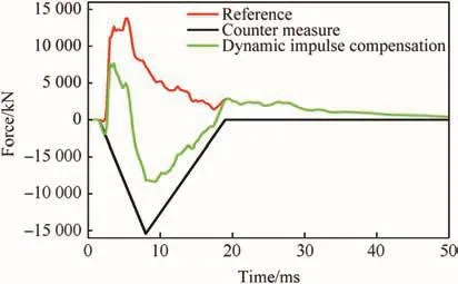
Fig.14.Forces acting on the vehicle after an HE detonation including the effect from DIC.
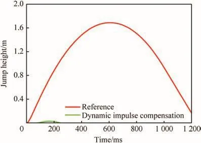
Fig.15.Jump height of the vehicle with and without DIC.
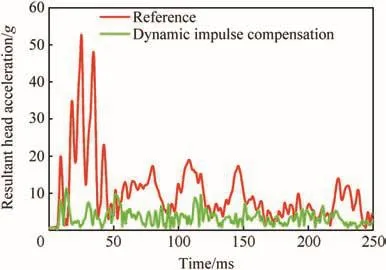
Fig.16.Resultant pelvic acceleration with and without DIC.
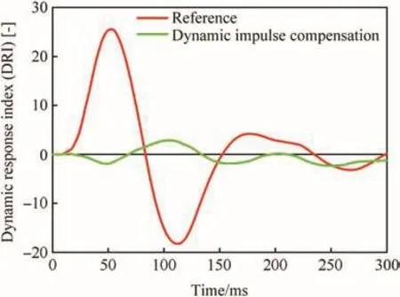
Fig.17.Dynamic response index with and without DIC.
The pelvic acceleration peak without DIC is 52 g and reaches 25 ms after detonation.With the use of DIC,the pelvic acceleration is clearly reduced and stays under 10 g.The dynamic response index without DIC reaches a maximum of 25,which is over the STANAG limit of 17.7.With DIC,the maximum DRI value is below 3.The probability of suffering injuries in the spine region is therefore highly reduced with DIC.The resultant head acceleration is given in Fig.18.The head acceleration peak is again clearly reduced with DIC(from 45 g without DIC to 9 g with DIC).Loads onto the lumbar spine and the head are highly reduced with DIC.
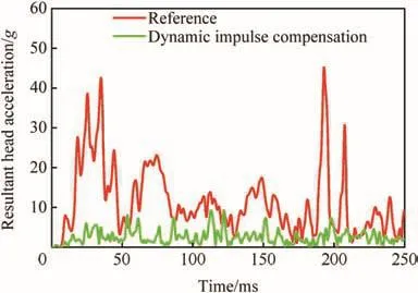
Fig.18.Resultant head acceleration with and without DIC.
6.Conclusions
In this work,two concepts for the reduction of global IED effects on military vehicles were examined.In a first step,the scaled model vehicles were used for a series of experimental test to optimize the vehicle geometry with respect to momentum transfer.The results show that the momentum transfer from the IED detonation to the vehicle can be reduced with a V-shaped vehicle hull.The size of the reduction effect depends on the definition of ground clearance and the IED position.However,a reduction was in the examined parameter range always observable.The experimental results were used to validate the numerical simulation models for the analysis of IED effects on vehicles and occupants.Hybrid-III software dummies were used to determine selected injury criteria for occupants due to an IED detonation near the vehicle.
The simulation models were used for a detailed assessment of the DIC concept.The principal functionality of DIC was already presented in Ref.[11]with the help of the scaled technology.It is based on an ejection system that transfers a global momentum onto the vehicle to compensate the IED detonation effects.This work concentrated on the principal design parameters of DIC and the effects on the occupants.The analysis was done with the help of original size generic vehicles and numerical simulation tools.For a defined buried IED charge,the detailed injury criteria for the occupants were evaluated.The selected criteria were DRI,pelvic acceleration and head acceleration.It was shown that the injury criteria were significantly lower with the help of DIC.The principal applicability of the concept DIC was confirmed by these additional results.Together with an optimized vehicle hull shape,a significant reduction of global acceleration effects is possible.The weight,size and position of the ejection units for DIC were not yet optimized but need to be studied in the future for the development of a practical system.For integration in an armoured vehicle,an attention should also be drawn to possible collateral effects of the dynamical impulse compensation DIC.
The authors want to thank Herr TRDir K.Hüsing from the German test range WTD-91 GF-440 in Meppen and Herr TRDir K.Neugebauer from BAAINBw for funding this work.
[1]Heider N,Denefeld V,Holzwarth A.Methods for the analysis of global IED effects on military vehicles.In:5th European Survivability Workshop,Alesund Norway,8-10;June 2010.
[2]Neuberger A,Peles S,Rittel D.Scaling the response of circular plates subjected to large and close-range spherical explosions.Int J Impact Eng 2007;34:874-82.
[3]Zorpette G.Countering IEDS,IEEE spectrum;2008.
[4]Anderson C,Behner T,Weiss C.Mine blast loading experiments.Int J Impact Eng 2011;38:697-706.
[5]Wenzel AB,Esparza ED.Measurements of pressures and impulses at close distances from explosive charges buried and in air.SwRI-report;1972.
[6]Held M.Blast effects with the Held momentum method.21st International Symposium on Ballistics,Adelaide;2004.
[7]Laine L,Sandvik A.Derivation of mechanical properties of sand.In:Proceedings of the 4th Asia-Pacific Conference on shock and Impact loads on structures.Singapore:CI-Premier PTE LTD;November 2001.pp.361-8.
[8]Fiserova D.Numerical analyses of buried mine explosions with emphasis on effect of soil properties on loading.PhD thesis.Cranfield University;2006.
[9]Heider N,Klomfass A.Numerical and experimental analysis of the detonation of sand-buried mines.22nd International Symposium on Ballistics,Vancouver;2005.
[10]Nilakantan G,Tabiei A.Computational assessment of occupant injury caused by mine blasts underneath infantry vehicles.Int J Vehicle Struct Syst 2009;1(1-3):50-8.
[11]Heider N,Denefeld V,Holzwarth A,Sättler A,Salk M.Vehicle protection against global IED effects.27th International Symposium on Ballistics,Freiburg Germany;2013.
[12]Noeske E.Simulation der Insassenbelastung bei detonativer Fahrzeugbelastung.Bachelor thesis.Württemberg Lörrach:Duale Hochschule Baden;2010.
[13]Denefeld V,Heider N,Salk M,Sättler A,Holzwarth A.Schutz gegen globale IED Wirkungen.Symposium“Ballistik in Forschung und Technologie 2014”,Mannheim;January 2014.
[14]Chung Kim Yuen S,Langdon GS,Nurick GN,Pickering EG,Balden VH.Response of V-shape plates to localized blast loads:experiments and numerical simulations.Int J Impact Eng 2012;46:97-109.
[15]Brinkley JW,Shaffer JT.Dynamic simulation techniques for the design of escape systems:current applications and future air force requirements.Symposium on Biodynamic Models and their Applications,Report No.AMRL-TR-71-29.USA:Aerospace Medical Research Laboratory,Wright-Patterson Air Force Base;1970.
[16]Allied Engineering Publication.Procedures for evaluating the protection level of logistic and light armoured vehicles-mine threat,NATO/PfP unclassified,AEP-55,vol.2;2006.
[17]Yoganandan N,Pintar F,Boyton M,Begeman P,Prasad P,Kuppa S,et al.Dynamic axial tolerance of the human foot-ankle complex,962426.Warrendale,USA:Society of Automotive Engineers;1996.
- Defence Technology的其它文章
- Shock tube design for high intensity blast waves for laboratory testing of armor and combat materiel
- Long-rod penetration:the transition zone between rigid and hydrodynamic penetration modes
- Damage visualization and deformation measurement in glass laminates during projectile penetration
- On the continued acceleration of bomb casing fragments following casing fracture
- Numerical simulation of the natural fragmentation of explosively loaded thick walled cylinders
- Study of simple plane wave generator with an air-metal barrier

