Dynamic analysis of a guided projectile during engraving process
To XUE,Xio-ing ZHANG,*,Dong-hu CUI
aSchool of Energy and Power Engineering,Nanjing University of Science and Technology,Nanjing 210094,China
bNavy Academy of Armament,Beijing 100061,China
1.Introduction
Guided projectile is meant to be a precision location strike system and have the excellent accuracy of impact due to the delicate design of the inner electronic components.But if the electronic components do not work well in the projectile,its accuracy will be impaired.The dynamics of a guided projectile have been observed to cause a large number of electronics failures in projectile,such as the impact and the separation among electronic components,which are described in Ref.[1].There have been previous studies about the dynamics of the guided projectile.Jiang and Guo[3]dealt with the linear dynamic response of a gun,including the effects of projectile gravity and acceleration.Wang and Zhang[5]established the dynamics model of projectile in consideration of the actual movement of the projectile and inertial breech.Also,Chu and Zu[6]and Cordes et al.[7]analyzed various reasons which cause the unexpected projectile vibration,such as the mass bias,static unbalance and dynamic unbalance.
From these researches,it can be known the vibration of the projectile frequently takes place in the barrel.However,the vibration which could cause the failure of inner electronic components may take place at the moment when the projectile is experiencing loads,especially in a strong transient situation[3-7].During the engraving process,the band is squeezed into the gun bore by the high-pressure propellant gas.Because of the stringent requirement of preventing the propellant gas leakage,the diameter of the band around the projectile is larger than the inner diameter of barrel,which is called the radial exceeding value,so that the projectile has to overcome the resistance R(t)when it is pushed into the gun bore by the propellant gas,as shown in Fig.1.The radial exceeding value is shown in Fig.2.
According to the experiments in Refs.[8]and[9],the time of the engraving process is only about a few milliseconds,the resistance R(t)reaches 123 kN[9],but it drops to sliding friction instantaneously at the end of the engraving process.The transient resistance is changed to be about 120 kN.However,Jin[8,9]focused on the deformation of the band and neglected the dynamic response of the projectile in the experiment.Therefore,it is important to investigate the dynamic response of the guided projectile during the engraving process.Meanwhile,since the resistance disappears abruptly after the band completely enters the gun bore,it is quite necessary to explore the dynamic response of the guided projectile in the milliseconds following the engraving process.
Hence,the purpose of this paper is to study the axial dynamics characteristics of the guided projectile during the engraving process.The underlying idea for the guided projectile is analogous to the analytic method in Refs.[2],in which the projectile center of gravity(C.G.)moves backward when the projectile is compressed by gas pressure.Jin's one dimensional engraving model which was established by coupling with the interior ballistic equations was used to gain the axial engraving resistance.The dynamic response of the guided projectile in the several milliseconds after the engraving process was researched.The influences of band geometry and material on the dynamic response of guided projectile were analyzed,too.This work proposed the theoretical reference for the further research on the failures and reliability of electronics in guided projectiles.
2.Dynamic model of the guided projectile during engraving process
2.1.Engraving process
During the engraving process,the resistance is deemed to be caused by the band deformation,but the projectile dynamics should be considered because of a strong transient variation of projectile.Generally,the projectile velocity is low in the extremely short engraving process,so that the air pressure ahead of the projectile could be neglected in the engraving dynamic model.Since the pressure on the base of the projectile is generated by propellant gas,the engraving dynamic model must include the equation of propellant burning rate and the equation of propellant shape.And the velocity equation and the energy conservation equation should be considered to form the interior ballistic equations.
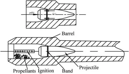
Fig.1.Schematic diagram of a typical gun and its initial stress.
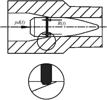
Fig.2.Partially enlarged drawing of touch between band and barrel.
A lumped parameter model[8]is a simple but useful representation of the interior ballistic cycle,embodying such assumptions as uniform and simultaneous ignition of the entire propellant charge.Combustion is assumed to take place in a smoothly-varying,well stirred mixture,and the burning rate is determined by the instantaneous,space-mean chamber pressure.In this paper,the interior ballistic equations are as follows
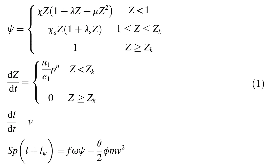
where ψ is the propellant burned fraction;Z is the relative burned thickness rate,Z=e/e1;e1is the half thickness of the multiple-perforated propellant;e is the burned thickness;Zkis the relative burned thickness rate at the end of propellant combustion;dZ/dtis the burning speed of propellant and the experimental data u1depends on the different kind of propellants;l is the tube length;lψis the ratio of chamber free volume to bore area;f is the propellant impetus,which is used to express the generated energy per kilogram of propellant;ω is the mass of propellant;p is the average gas pressure behind the projectile;v is the projectile velocity;S is the sectional area of barrel; θ=k-1,kis adiabatic index;and φ is a coefficient accounting for secondary energy losses.
The force on the projectile is analyzed with the interior ballistic equations,as shown in Fig.2.The dynamics equation is as follows[8-10].

where m is the mass of projectile;Spd(t)is the force on the base of projectile;R(t)is the resistance;x is the projectile displacement;and pd(t)is the pressure on the base of projectile which could be gained by p.
In order to consider the dynamic loads,Jin's engraving model[8]is used to gain the axial engraving resistance.R(t)is divided into two parts while the band enters the gun bore.One is the internal friction of the material,FR,under the dynamic loads and the other is FDcaused by the deformation of band.According to[8,9],the resistance R(t)formula is as follows:

where FR=Ddx/dt,D=2ξmωnis the damping coefficient caused by the internal friction of the materialwhere K is the stiffness of the band.FD=Kx,where x is the projectile travel during the initial process.When the stress on the band reaches the material shearing yield limit stress τs,the deformation of the band is plastic deformation.Substituting Eq.(3)into Eq.(2),the equation of projectile motion can be gained as follows:

2.2.The dynamics of projectile
The model of projectile we shall begin with is very simple.We assume that the projectile is a right circular cylinder and all the calculations of projectile dynamics is taken relative to the projectile base,which is different from that in Ref.[2].We assume that the projectile wall is thick enough so that bulging is negligible(This is just for illustration purposes as bulging can be significant in some projectile designs).This projectile is shown in Fig.3.
We could calculate R(t)via Eqs.(1)-(4).The gap between projectile and band is neglected so that they move together.
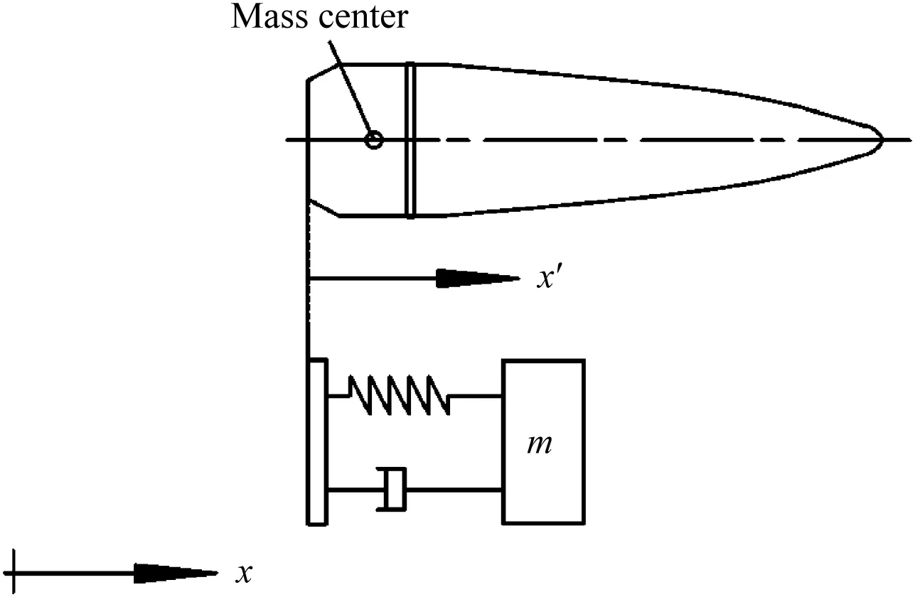
Fig.3.Simple system model of projectile.
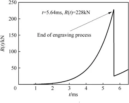
Fig.4.Resistance on band.
The dynamic model shown in Fig.3 is represented by the following differential function

3.Result and analysis
In this section,the guided projectile during the engraving process is researched.The influences of band geometry and band materials on the dynamics of the guided projectile are analyzed in detail.All the calculations performed are for a guided projectile with 1 m in length and 130 mm in diameter.And the dynamics of projectile in this paper is relative to the projectile base.
3.1.The dynamics of guided projectile during engraving process
To understand the dynamic response of a guided projectile generally,the guided projectile with a typical engraved band is used as a demonstration case in which the material is copper.The width of band is 0.025 m,and the exceeding radial value is 0.001 times of the projectile diameter.
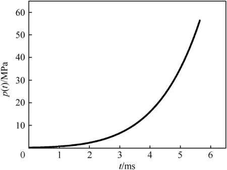
Fig.5.Pressure on projectile.
As shown in Figs.4 and 5,it is about 5.64 ms when the band completely enters the gun bore,the resistance reaches 228 kN,and the gas pressure reaches 56.4 MPa.At the end of the band engraving process,the resistance drops to 23 kN instantaneously.According to Fig.6,although both the gas pressure and the resistance increase sharply,the resultant force changes slowly so that C.G.velocity increases smoothly.As shown in Fig.7,C.G.acceleration increases as the band is squeezed in the gun bore.Yet,large oscillations take place at the beginning of motion.
The resistance drops to sliding friction suddenly when the band completely enters the gun bore and the variation in resistance is about 205 kN.In such a special stress situation,an analysis in the few milliseconds after the band enters gun bore is very important.It can be seen from Figs.8 and 9 that there are huge variations in the projectile response at the moment when the band is completely squeezed into the gun bore.At the same moment,the resistance drops to sliding friction abruptly.In the milliseconds after the resistance drops to sliding friction,the maximum C.G.velocity relative to projectile base is about 2.9 m/s and the maximum C.G.acceleration relative to projectile base is 10,576 m/s2.Under such inertia force and shock,there is a very serious effect on the electronic components.The separation and even failure of components may easily occur in the guided projectile.
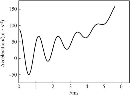
Fig.7.C.G.acceleration relative to projectile band during engraving.
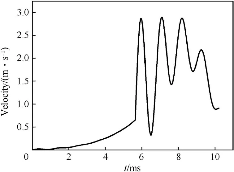
Fig.8.C.G.velocity in the first 10 ms.
Fig.10 shows the dynamic friction in 5 ms after the band completely enters the gun bore.Here the effects of temperature and relative velocity are ignored and the friction coefficient is set as a constant.Fig.11 shows the gas pressure.
During the several milliseconds following the engraving process,as the gas pressure increases,the sliding friction is small relative to the gas pressure.The C.G.velocity relative to projectile vibrates fiercely,as show in Fig.12.The resultant force on the projectile compresses it so that the location of C.G.accelerates to move backwards.Also,the smooth increase in pressure drives the compression ratio to be a constant.As shown in Fig.13,C.G.acceleration decreases gradually towards-300 m/s2.
3.2.The effects of different engraving bands on projectile dynamic response
In this section,the numerical simulation program of the projectile vibration function is modified to illustrate how the different width and exceeding radial value affect the projectile dynamic response.The size of an engraving band is varied for two different cases:different widths with the same exceeding radial value;and different exceeding radial values with the same width.The influence of different band materials on the projectile dynamic response is also researched.
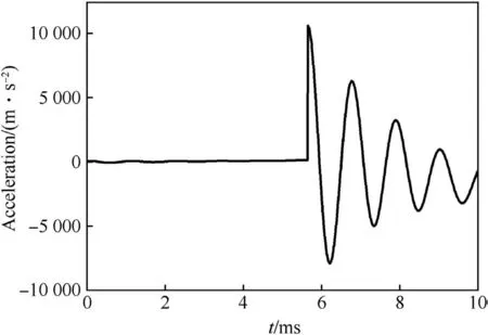
Fig.9.C.G.acceleration in the first 10 ms.

Fig.10.Resistance after the band completely enters gun bore.
Five different width assumptions within the accepted range are analyzed.The assumed widths are 0.021 mm,0.023 mm,0.025 mm,0.027 mm and 0.029 mm.In this part,we are interested in the several milliseconds after the band completely enters the bore.As the description in Subsection 3.1,the vibrations during this period following engraving process are fiercer relative to the engraving process.The time domain response and frequency domain response of the projectile C.G.acceleration to different band widths are shown in Fig.14.From the frequency domain responses,the frequency with high amplitude is mainly concentrated in the frequency band from 0 Hz to 2 Hz.This frequency band contributes the most energy to maintain the vibration of projectile C.G.As shown in Fig.14(a)-(e),there are substantial changes in the acceleration amplitude.A large band width leads to more substantial vibrations.This is because wider band has greater engraving resistance than narrower band.
In order to seal the gun bore,the diameter of the engraving band is larger than the barrel inner diameter.The projectile could move only if the resultant force on the base of projectile is bigger than the shear force between the gun bore and the band.Therefore,the radial exceeding value plays the crucial role of preventing the propellant gas from leaking.The effect of radial exceeding value on the dynamic response of guided projectile is discussed as follows.During calculation,the band width is set as 0.025 m.According to Ref.[11],the maximum radial exceeding value is less than 0.0025 times of the projectile diameter to avoid excessively fierce collisions meanwhile the minimum radial exceeding value has to be bigger than 0.001 times of the projectile diameter to prevent the gas from leaking.Four different radial exceeding values are chosen within this range to show its effect on the dynamic responses of projectile C.G.The radial exceeding value δ is expressed as a multiple of projectile diameter.As shown in Table 1,the base frequency and its corresponding amplitude in the systems with different radical exceeding values are almost unchanged.
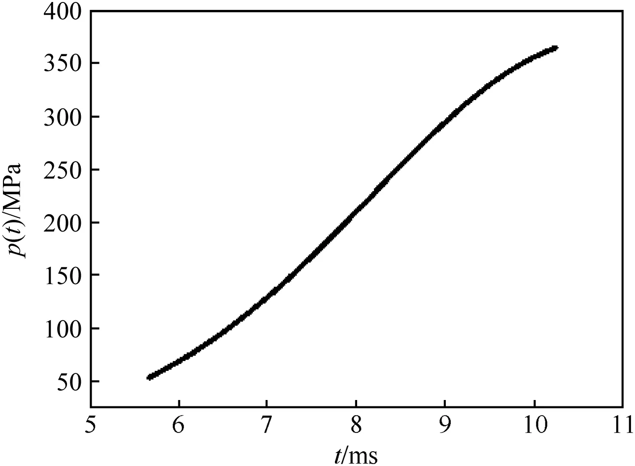
Fig.11.Gas pressure after the band completely enters gun bore.

Fig.12.Velocity after the band completely enters gun bore.
According to the two cases,we conclude that the width of the band has a great influence on the acceleration vibration of guided projectile.However,the different exceeding values have little effects on the dynamic response of projectile C.G.
During the engraving process,the band is designed to have the functions of preventing the gas from leaking and stabilizing the axial position of projectile.So the band material must have good flexibility and malleability to keep close contact with the inner wall of the barrel.Lots of materials could be used for the band.In this part,the effects of different band material characteristics on the dynamic response of the projectile C.G.acceleration are calculated for three kinds of materials,such as MC nylon,copper,and steel,which are commonly used in the design process.The properties of the three materials are listed in Table 2.

Fig.13.Acceleration after the band completely enters gun bore.
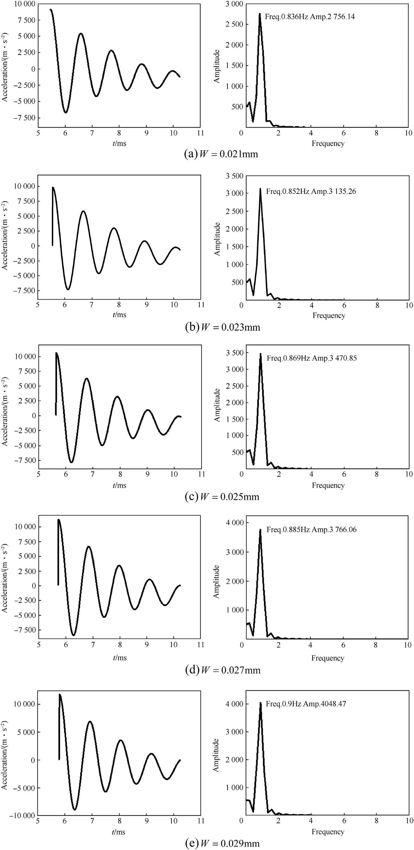
Fig.14.Dynamic response of projectile C.G.acceleration to different band widths.

Table 1The base frequency and amplitude of the system with different radial exceeding values.

Table 2The material properties of MC nylon,copper,and steel.
During numerical calculation,we assume that the band is deformed if the stress reaches 0.8 times of the material yield strength,which is an empirical value.In the calculation model of the engraving process,the stiffness of band depends on the elastic modulus of material.As shown in Fig.15,the time domain response and frequency domain response of the projectile C.G.acceleration in the systems with different band materials are presented.The characteristic frequencies of different band materials are successfully extracted in the frequency domain.The amplitude at 0 Hz shows the inherent constant energy in the system,and the amplitude at 0.88 Hz shows the energy which maintains the vibration of the projectile C.G.As shown in Fig.15(a)-(c),the dynamic response of the system with MC nylon contains more constant energy and less vibration energy in the frequency domain compared to the systems with the other two kinds of materials.The reason for this is that the modulus of elasticity of MC nylon is smaller than those of other two materials.Also,the proportion of the energy,which could lead vibration,increases with the increase in modulus of elasticity.
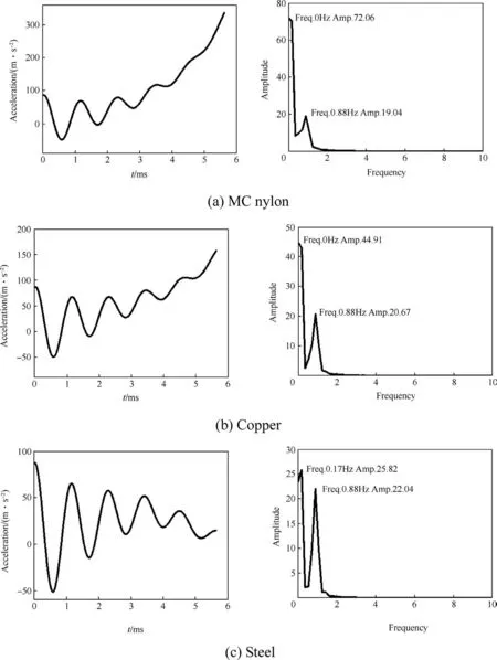
Fig.15.The dynamic response of projectile C.G.in the system with different band materials during the engraving process.
4.Conclusions
In this paper,the dynamics of the guided projectile during the engraving process were researched.The time domain and frequency domain responses of the projectile C.G.evidently show the influences of the engraving band geometry size and material on the dynamic response of the guided projectile.From the results,it can be concluded that the guided projectile dynamic response is strongly affected by the engraving force and the band characteristics.
After the band completely enters the gun bore,the resistance drops sharply.This abrupt resistance leads to an extreme fierce vibration of the guided projectile,and this vibration may easily lead to a separation or failure of the electronic components.
As shown in the frequency domain,the dynamic response of the guided projectile is very sensitive to the engraving band width;meanwhile the radial exceeding value has little effect on the dynamic response of the projectile during the engraving process.The band material has been predicted to affect the dynamic response of the guided projectile significantly.The material with a smaller modulus of elasticity contains more constant energy and less vibration energy.It can be concluded that a band with small modulus of elasticity could be more stable than a band with high modulus of elasticity.
Many factors can affect the engraving process,such as force cone angle,rifling and so on.In this paper,the engraving model was used for calculating the dynamics of projectile C.G.,and the axial load was mainly considered.The multidimensional dynamics of projectile C.G.could be considered in the future work.
The research was supported by the Research Fund for the Natural Science Foundation of Jiangsu province(BK20131348), Key Laboratory Fund (Grant No.9140C300103140C30001),People's Republic of China.
[1]Oman J.National Missile Defense-an obligation.USAWC Strategy Research Project NO.20000320095;2000.
[2]Carlucci D,Cordes J,Morris S,Gast R.Muzzle exit(set forward)effects on projectile dynamics.Technical Report ARAET-TR-06003,AD-E403 082.Picatinny Arsenal,New Jersey:Armament Research Development and Engineering Center;2006.
[3]Jiang M,Guo X.On the vibration of tube due to acceleratory moving projectile.J Ballist 2002;14(3):57-62.
[4]Li W,Ma J,Sun H,Chen L,Qiao L.Dynamic analysis for inertial Bayonet-chamber process of a projectile.J Vib Shock 2011;30(5):161-3.
[5]Wang Y,Zhang X.Vibration analysis of rarefaction wave launch device in moving mass.J Vib Shock 2009;28(8):144-7.
[6]Chu S,Zu H.Basic simple modeling of balloting motion of rail gun projectiles.Picatinny Arsenal,New Jersey:Armament Research Development and Engineering Center;1991.Fire Support Armament Center,AD-A237938.
[7]Cordes J,Vega J,Carlucci E,Chaplin R.Structural loading statistics of live gun firings for the army's Excalibur projectile.Armament Research Development and Engineering Center;2005.AD-E403 040.
[8]Jin Z.The interior ballistics of gun.Beijing:Beijing University of Science and Technology Press;2007.Chap.1-2.
[9]Jin Z,Zeng S.A study on the calculation of the engraving process on projectile.Acta Armamentarii 1991;12(2):7-13.
[10]He Y.An one-dimensional model for the projectile engraving process and its calculation.J Ballist 1994;4:24-8.
[11]Wei H.Projectile design theory.Chapt.1.Beijing:National Defense Industry Press;1985.
- Defence Technology的其它文章
- Shock tube design for high intensity blast waves for laboratory testing of armor and combat materiel
- A passive method to stabilize an airborne vehicle
- Experimental investigation of a cook-off temperature in a hot barrel
- Formulation development and characterization of cellulose acetate nitrate based propellants for improved insensitive munitions properties
- Deconsolidation and combustion performance of thermally consolidated propellants deterred by multi-layers coating
- Burning characteristics of microcellular combustible objects

