Structural Scheme Optimization Design for the Stationary Platen of a Precision Plastic Injection Molding Machine
REN Bin *,ZHANG Shuyouand TAN Jianrong
1 State Key Laboratory of Fluid Power Transmission and Control,Zhejiang University,Hangzhou 310027,China
2 Department of Civil and Architectural Engineering,City University of Hong Kong,Hong Kong 999077,China
1 Introduction*
The manufacturing of injection molding machines is one of the world’s fastest growing industries in accompany with the application of plastic production[1–2].The development of precision injection molding techniques has attracted more and more attention.Precision injection molding techniques include injection molding process and injection molding machines.
Injection molding process and mould design have critical effects on the quality of plastic parts.WANG,et al[3],studied on the residual stresses of the thin-walled injection molding.The effects of process conditions were investigated for the analysis and measurement of the deformation of injection molding plastic products[4].Selection the proper setting for an injection molding process is important to influence the behavior of the polymeric material shaping[5].DING,et al[6],proposed a new multi-objective optimization algorithm KSVC-SPEA to solve the optimization problem of overall performance of the HT160X1N high-speed injection molding machine.KWAK,et al[7],optimized injection molding conditions using a neural network program based on simulation results.CHEN,et al[8],applied the design of experiments approach to determine an optimal parameter setting of injection molding.LEE,et al[9],established a systematic methodology and knowledge base for an injection-molding mould design in a concurrent engineering environment.FOLGADO,et al[10],compared two mould manufacturing alternatives based on a life cycle cost model.
Injection molding machines can inject the melted plastics into the mould to produce plastic product.Many researchers have focused on the design of injection molding machine.A synchronized system has been developed to support conceptual design of injection molding machine on the Internet[11].Injection molding machines are composed of injection unit,clamping mechanism,injection moulds,hydraulic system,and control system.TSAI,et al[12],presented pragmatic techniques for mechatronic design and injection speed control of an ultra high-speed plastic injection molding machine.BULL,et al[13],have developed a novel wear tester to simulate the conditions of wear for the selection of coatings and surface treatments.JACHOWICZ[14]discussed the factors characterizing the work and functional properties of a clamp unit.
Clamp unit plays an important role in determining the precision of the design of injection molding machines.Every clamp unit needs to conform to certain requirements.It keeps the mould effectively closed during the injection and holding-pressure stages.It is necessary to study the structures of the clamp unit in detail.The design of the internal circulation two-platen clamp unit was carried out with high molding precision[15].However,a toggle clamp unit,with excellent performances,is relatively more economy.A five-point double-toggle clamp unit has its capacity to generate large clamping forces.It is widely used in the injection molding machines.HUANG,et al[16],explored the effect of key design parameters and adopted genetic algorithm to obtain the optimal solution of a clamping mechanism.SUN[17]introduced the self-organization method to optimize the topology of the stationary platen.SASIKUMAR,et al[18],analyzed the premature failure of a tie bar in a 1500 kN plastic injection molding machine and concluded that the tie bar has failed at the root.LIN,et al[19],investigated the friction effect at pin joints for the five-point double-toggle clamping mechanisms of injection molding machines.
In order to satisfy the requirements of high precision and cost saving,a manufacturer of injection molding machines has improved upon a SE-160 precision plastic injection molding machine which is the five-point double-toggle clamp unit with 1600 kN clamping force.The clamp unit includes four tie bars,stationary and movable platens where the stationary platen is a key component of the clamp unit.
The five-point double-toggle clamp unit in the SE-160 precision plastic injection molding machine has a stationary platen size of 780 mm length and 735 mm width,a moving platen of 640 mm length and 640 mm width,and four tie bars of 73 mm diameter and 2.21 m length.The distance between the stationary platen and the moving platen is 470 mm,and the toggle stroke is 420 mm.A schematic of the toggle-type clamp unit is shown in Fig.1.

Fig.1.A five-point double-toggle clamp unit in a SE-160 injection molding machine
The stationary platen in a SE-160 precision plastic injection molding machine is subjected to a cyclic loading during the motion of mold closing and opening.It appears to be bending by the high stress concentrations of tie bars.In order to reduce the deflection of the stationary platen,topology optimization could be introduced.Structural topology optimization as a generalized shape optimization problem has received considerable attention recently.Various families of structural topology optimization methods have been extensively developed,such as genetic algorithms and ant colony optimization algorithm[20–21].RONG,et al[22],proposed an efficient structural topological optimization method to obtain a well defined final design with multi-displacement constraints.
The stationary platen in a SE-160 precision plastic injection molding machine can be considered as a large cast-iron-made block which fixed to the frame.The topology optimum design provides the stationary platen with high rigidity and even stresses distribution.Optimized casting design has decreased the movement inertia and improved the responsive speed for all machine operations.Moreover,two recommended schemes of the topology optimization are given to extend the operation life of the stationary platen and improve the precision of positional repeatability in a 1600 kN plastic injection molding machine.
The remainder of this paper is organized as follows:Section 2 introduces the FEA method to structural topology optimization of the stationary platen in a SE-160 precision plastic injection molding machine.Section 3 gives two recommended optimization structures of the stationary platen,and compares them with the prototype platen.Section 4 provides a discussion on the sample prototype.Section 5 is the conclusion.
2 Topology Optimization for the Stationary Platen of a SE-160 Precision Plastic Injection Molding Machine
The stationary platen of a clamp unit has a bad force condition during the injection and holding-pressure stages.The stiffness and strength of the stationary platen have a great extent effect on the mould life and the quality of plastic parts.Therefore,we could optimize the structure of the stationary platen using the method of finite element analysis(FEA)which is a mature continuum topological optimization method.The optimization objective of FEA is to reduce the deformation and improve the stiffness of the stationary platen under the structural constraints.Fig.2 shows the process of the structural topology optimization of the stationary platen in a SE-160 precision plastic injection molding machine.
2.1 Basic assumptions of the force conditions of the stationary platen
Topology optimization design of the stationary platen can be carried out in a SE-160 precision plastic injection molding machine with clamp force 1600 kN.The material of the stationary platen is QT450-10,where the Young’s modulus of each element is set to 1.69 and the Poisson’s ratio is 0.3.Due to the symmetry of both the structure and the load condition of the platen,we selected 1/4 structure of the platen as the object,shown in Fig.3.
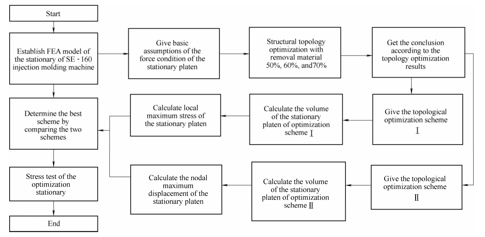
Fig.2.Process of topological optimization of the stationary platen in a SE-160 injection molding machine

Fig.3.1/4 structure of the stationary platen
In order to save computing resources and give prominence to the influence of forming precision,we have made the following basic assumptions of the force conditions of the stationary platen.
(1)The stationary platen is subjected to the maximum bending during the injection and holding-pressure stages.So we could analyze and optimize the stationary plate during the injection and holding-pressure stages to ensure the stiffness and strength of the stationary platen.
(2)Four tie bars have the movement guide function for the stationary platen,and they have less effect on the deformation of stationary platen during the holdingpressure stages.The structural topology optimization mainly involves the calculations on the stiffness and strength of the stationary platen,so the influence of tie bars can be negligible.
(3)During the injection and holding-pressure stages,the internal pressure of the clamping cylinder is 16 MPa.Considering the influence of forming accuracy,the pressure of clamping cylinder could be converted to Z displacement constraints at the wall of clamping cylinder during the optimization process.
(4)The stationary platen is fixed to the frame.Compared with the clamping force of 1600 kN,the gravity of the stationary platen can be negligible.
(5)We take the structure of the stationary platen as a cast iron.The screw holes and other small holes can be negligible,as to simplify the structures of the stationary platen.
2.2 Finite element model of the stationary platen
According to the above assumption,we can build the 3D model of stationary platen,and take its 1/4 structure as the object of finite element analysis.The process of finite element analysis(FEA)is shown in Fig.4.
Step 1:The 3D model of a stationary platen can be established.It can be exported as the parasolid format(file suffix.X_t).Then,it can be imported to the software of ANSYS.
Step 2:We set the material properties of the stationary platen,including elastic modulus and Poisson’s ratio.The tetrahedral finite element using SOLID92 is adopted into the meshing model,and the finite element size is of 0.015 m.
Step 3:According to the simplifications and assumptions,constraints and loads are added to the stationary platen as follows:
(1)Add Z-displacement constraints to the active surface of clamping cylinder.
(2)Add symmetry constraints to the two truncation face of the stationary platen.
(3)Apply the uniform load to the mould loading surface,and the surface pressure is equal to 16 MPa.

Fig.4.Model of finite element in the stationary platen
The volume of the stationary platen of the SE-160 precision plastic injection molding machine is about 0.012 983 m3.The results of the FEA of the stationary platen are as follows:
(1)The maximum displacement of the node is 0.186 mm,and it occurs near the injection hole which is in the center of the stationary platen.
(2)The displacement values of the node decrease outward from the center,as shown in Fig.5.
(3)The maximum stress of the stationary platen is 324 MPa,which has satisfied the strength requirements.
(4)The maximum stress distribution is happened on the corner of clamping cylinder,shown in Fig.6,and it arises from the fluid pressure within the clamping cylinder.

Fig.5.Node displacement cloud of the stationary platen(mm)
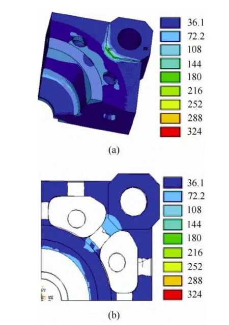
Fig.6.Node stress cloud of the stationary platen(MPa)
2.3 Topology optimization design of the stationary platen
The aim of topology optimization design is to obtain a reasonable structure of the stationary platen through improving strength and stiffness as well as saving material.Based on the method of FEA,topology optimization design gives each unit a pseudo-density value through design variables,and takes the boundary conditions as a constraint function.
The mathematical model of topology optimization is established by variable density method which can be described as

s.t.,

where G(ρ)—Strain energy of the platen,
ρj—The jth element density,
k—Percentage of removal material,
V—Volume of prototype structure of the platen for the topology optimization,
Vj—The jth element volume,where N is the total quantity,
ρmin—Lower limit of element density.
Material density is as the design variable of topological optimization,so the problem of topology optimization as the material optimal distribution can be resolved by the variable density method using the software ANSYS.The distortion energy of the structure is treated as the optimization objective with the satisfaction of the structural constraints,namely,we need to increase the structural stiffness.
In the case of saving material of 50%,60%,and 70%,the structures of the topology optimization are shown in Figs.7–9 with the iterative calculations.
In conclusion,we need to retain more material from the axis of locking cylinder to the center of injection hole.Meanwhile,we need retain more material around the center of the injection hole in the stationary platen.

Fig.7.Topology optimization of the stationary platen with the removable material 50%
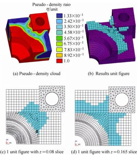
Fig.8.Topology Optimization of the stationary platen with the removable material 60%
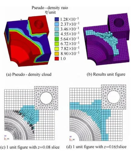
Fig.9.Topology optimization of the stationary platen with the removable material 70%
3 Two Design Schemes of Structural Topology Optimization for the Stationary Platen
According to the results of topology optimization,we can obtain the improvement schemes of stationary platen,by decreasing the local stress concentration,optimizing the large displacement zone,and saving the superfluous material.
3.1 Scheme I of structural topology optimization of the stationary platen
Scheme I of the stationary platen is shown in Fig.10.It has been deduced from the topology optimization and has the different reinforcing ribs from prototype.In the injection and holding-pressure stages,the structure of scheme Ι of the stationary platen can be analyzed by the FEA.The deformation and stress of this structure is shown in Fig.11.The maximum displacement of Node is 0.185 mm,near the center hole in the stationary platen,the values of node-displacement decrease outwards from the center.The maximum stress of the platen is 298 MPa.It satisfies the strength requirement.The maximum stress distribution is around the corner of clamping cylinder.
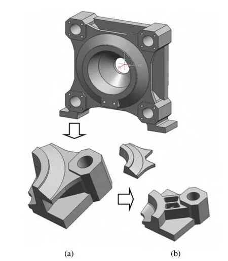
Fig.10.Scheme I of the stationary platen
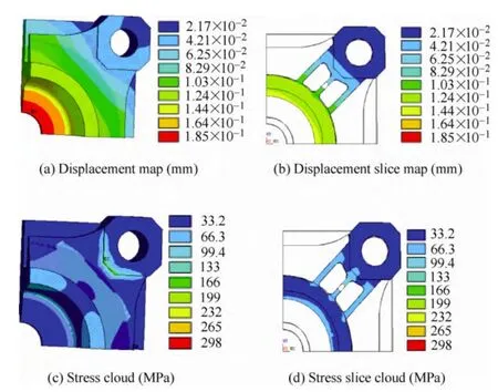
Fig.11.Deformation and stress of the structure of scheme I
The performance of the scheme I of the stationary platen can be obtained and compared with prototype platen,shown in Table 1.

Table 1.Performances comparison of two structures
Compared with the structures between scheme I and prototype,scheme I of the stationary platen reduced the volume by 10%,reduced the nodal maximum displacement by 0.54%,and reduced the local maximum stress by 8%.Therefore,scheme I of stationary platen could save material and improve the performance of the stationary platen significantly.
3.2 Scheme II of structural topology optimization of the stationary platen
The topology optimization scheme II of the stationary platen is shown in Fig.12.It has the different reinforcing ribs from prototype and scheme I.We can obtain the deformation and stress of the scheme II of the stationary platen by the FEA method.The maximum displacement is 0.184 mm,near the center hole in the stationary platen.The maximum stress of the platen is 256 MPa,which satisfies the strength requirement.The maximum stress distribution is around the corner of clamping cylinder.Structural performances comparison between scheme II and prototype is shown in Table 2.
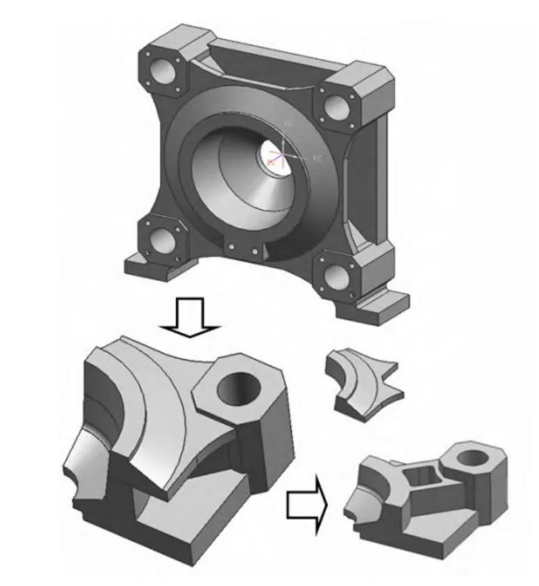
Fig.12.Scheme II of the stationary platen

Table 2.Performances comparison between scheme II and prototype
From the performances comparison between scheme II and prototype,we could safely draw the conclusion that:compared with the structures between scheme II and prototype,scheme II of the stationary platen reduced the volume by 9.53%.Nodal maximum displacement can be reduced by 1.08% while the local maximum stress reduced by 21% in scheme II.Therefore,scheme II of the stationary platen is better than scheme I.
4 Implementation and Examples
In recent years,we have had the opportunity to cooperate with several industrial partners to implement and test our method.We applied our methods to design high precision type plastic injection molding machine with hydraulic and servo energy saving control system.A SE-160 commercial machine was produced by a famous plastic injection machine manufacture in China.The stationary platen of a plastic injection machine could be considered as a large cast-iron-made block with one large circular hole in its center for the injection barrel,and four small holes at its four corners for securing the tie bars.The platen is attached to the machine frame by means of two small legs at the left and right bottom corners.
To illustrate the effectiveness of the method,a photo of a commercial plastic machine is shown in Fig.13.It is clear that the stationary platen in the commercial machine is almost identical to the proposed design in this design.The strengthened ribs of scheme II structure in the commercial machines could be developed.It has been evolved through structural topology optimization to satisfy the key requirements of high stiffness and low cost.The proposed method herein,proved the effectiveness of scheme II of the stationary platen through a simple and systematic scientific way.

Fig.13.Scheme II of the stationary platen in a commercial machine
The optimal structure of the stationary platen incorporates and extends the excellent features and performance of our SE series machines.Equipped with an improved stationary platen,it provides excellent energy saving compared to traditional machines on the market today.The hydraulic system is self optimizing and only delivers the actual process requirement,without wasted energy.The cycle of the closed loop system will continually vary and optimize the flow and pressure requirement for the process.If no movement is required during the cycle,the system will stop,which significantly reduces power consumption.Typically power saving of 20%-80% is achievable,which is dependent on the process cycle parameters.Overall the SE series machine provides significant customer advantage for large machine energy saving.
5 Conclusions
In this paper,we focused on the topology optimization of the stationary platen in a SE-160 precision plastic injection molding machine and proposed two recommended optimization schemes to improve the precision of the clamp unit.By choosing the best alternative,the volume and the local maximal stress of the platen could be decreased,corresponding to cost-saving material and better mechanical properties.Our contributions of this paper are as follows.
(1)In order to reduce the deflection of the stationary platen with the weight constraints,the model of topological optimization of the stationary platen was established.
(2)The basic assumptions of the stress state of the stationary platen were proposed.Moreover,the method of FEA was introduced to optimize the structure of the stationary platen.
(3)The other two optimization schemes were deduced by the topology optimization.They are compared with the original structure of the stationary platen.
The improved design of a SE-160 precision plastic injection molding machine can be combined with energy efficient and precise hydraulic and servo control technology to provide the customers a fast and accurate production machine for all molding requirements,including lower power consumption,quiet and clean operation for environmentally friendly operation.The research of high rigidity clamping structure with the parameters coupling of hydraulic drive has paved a way for future work.
[1]MICHAELI W,HEBNER S,KLAIBER F.Geometrical accuracy and optical performance of injection moulded and injectioncompression moulded plastic parts[J].CIRP Annals-Manufacturing Technology,2007,56(1):545–548.
[2]ONG N S,KOH Y H.Experimental investigation into micro injection molding of plastic parts[J].Materials and Manufacturing Processes,2005,20(2):245–253.
[3]WANG T H,YOUNG W B.Study on residual stresses of thin-walled injection molding[J].European Polymer Journal,2005,41(10):2511–2517.
[4]KOVACS J G,SIKLO B.Test method development for deformation analysis of injection moulded plastic parts[J].Polymer Testing,2011,30(5):543–547.
[5]CASTRO C E,RIOS M C,LILLY B.Simultaneous optimization of mold design and processing conditions in injection molding[J].Journal of Polymer Engineering,2005,25(6):459–485.
[6]DING L P,TAN J R,WEI Z,et al Multi-objective performance design of injection molding machine via a new multi-objective optimization algorithm[J].International Journal of Innovative Computing Information and Control,2011,7(7A):3939–3949.
[7]KWAK T S,SUZUKI T,BAE W B,et al Application of neural network and computer simulation to improve surface profile of injection molding optic lens[J].Journal of Materials Processing Technology,2005,170(1–2):24–31.
[8]CHEN C P,CHUANG M T,HSIAO Y H,et al Simulation and experimental study in determining injection molding process parameters for thin-shell plastic parts via design of experiments analysis[J].Expert Systems with Applications,2009,36(7):10 752–10 759.
[9]LEE R S,CHEN Y M,LEE C Z.Development of a concurrent mold design system:a knowledge-based approach[J].Computer Integrated Manufacturing Systems,1997,10(4):287–307.
[10]FOLGADO R,PECAS P,HENRIQUES E.Life cycle cost for technology selection:A Case study in the manufacturing of injection moulds[J].International Journal of Production Economics,2010,128(1):368–378.
[11]HUANG G Q,LEE S W,MAK K L.Collaborative product definition on the Internet:a case study[J].Journal of Materials Processing Technology,2003,139(1–3):51–57.
[12]TSAI C C,HSIEH S M,KAO H E.Mechatronic design and injection speed control of an ultra high-speed plastic injection molding machine[J].Mechatronics,2009,19(2):147–155.
[13]BULL S J,DAVIDSON R I,FISHER E H,et al A simulation test for the selection of coatings and surface treatments for plastics injection moulding machines[J].Surface and Coatings Technology,2000,130(2–3):257–265.
[14]JACHOWICZ T.Construction of clamping units of injection molding machines[J].Polimery,2005,50(2):110–117.
[15]JIAO Z W,XIE P C,AN Y,et al Development of internal circulation two-platen IMM for thermoplastic polymer[J].Journal of Materials Processing Technology,2011,211(6):1076–1084.
[16]HUANG M S,LIN T Y,FUNG R F.Key design parameters and optimal design of a five-point double-toggle clamping mechanism[J].Applied Mathematical Modelling,2011,35(9):4304–4320.
[17]SUN S H.Optimum topology design for the stationary platen of a plastic injection machine[J].Computers in Industry,2004,55(2):147–158.
[18]SASIKUMAR C,SRIKANTH S,DAS S K.Analysis of premature failure of a tie bar in an injection molding machine[J].Engineering Failure Analysis,2006,13(8):1246-1259.
[19]LIN W Y,HSIAO K M.Investigation of the friction effect at pin joints for the five-point double-toggle clamping mechanisms of injection molding machines[J].International Journal of Mechanical Sciences,2003,45(11):1913–1927.
[20]WANG S Y,TAI K.Structural topology design optimization using genetic algorithms with a bit-array representation[J].ComputerMethodsin Applied Mechanics and Engineering,2005,194(36–38):3749–3770.
[21]LUH G C,LIN C Y.Structural topology optimization using ant colony optimization algorithm[J].Applied Soft Computing,2009,9(4):1343–1353.
[22]RONG J H,LIU X H,YI J J,et al An efficient structural topological optimization method for continuum structures with multiple displacement constraints[J].Finite Elements in Analysis and Design,2011,47(8):913–921.
