
Comparative Analysis of PSO Algorithms for PID Controller Tuning
2014-02-07 12:44TIMACGorankaBRAUTSanjinandIGULIRoberto
ŠTIMAC Goranka*,BRAUT Sanjin,and ŽIGULIĆ Roberto
Faculty of Engineering,University of Rijeka,Rijeka 51000,Croatia
1 Introduction
Active1magnetic bearings(AMBs)present a magnetic suspension technology which is used in a variety of rotating machines,such as turbo molecular pumps,flywheels,machine tool spindles etc.Their unique advantages,such as complete elimination of oil lubrication systems,absence of mechanical wear,low maintenance costs,programmable stiffness and damping,follow directly from their contactless suspension principle.However,these are multivariable systems which require properly tuned feedback loops in order to ensure stable rotor suspension.
Although the development of process control methodologies is rapid,PID control still remains the most widely used feedback control strategy in industry and academia in many applications,including AMBs[1–2].
Optimal control performances of PID controller can be achieved by identification of the set of the three adjustable gains,i.e.proportional gain,integral gain and derivative gain.For that purpose various tuning methods have been proposed,among which the most basic method is the Ziegler-Nichols method,developed by Ziegler and Nichols in 1942.It is an empiric method based on the well known analytical tuning rules,but which are known to give poor results in many cases[3–4],especially when applied to systems which involve higher order components,nonlinearity and/or uncertainties.
However,modern tuning methods based on artificial intelligence techniques,such as neural networks,fuzzy-logic[5–7]and neural-fuzzy,can also be applied.In addition,many methods based on evolutionary computation algorithm can be applied,such as genetic algorithm[8],particle swarm optimization(PSO)[9–13]and ant colony optimization[14].
PSO has gained wide recognition since its development by KENNEDY and EBERHART in 1995,due to its ability to provide solutions efficiently,requiring only minimal implementation effort[15].Also,the ability of PSO to adapt easily its components to a desired form,implied by the problem at hand,has placed PSO in a prominent position among other intelligent optimization algorithms[16].Due to the good properties of the PSO algorithm,it has evolved nowadays as a new optimization approach,which can be applied in a variety of applications,such as in fault identification[17],in estimation of the filter parameters[18],in control engineering for PID controller gain tuning[9–13]etc.Although the PSO approach has been widely investigated in PID controller tuning,its direct application to rotor/AMB systems is scarce and rarely found in the published literature.
In this paper the performance analysis of the PSO algorithms for PID controller tuning for a rotor/AMB system is carried out.Two PSO algorithms,namely PSO with linearly decreasing inertia weight(LDW-PSO)and PSO algorithm with constriction factor approach(CFA-PSO),are independently implemented and tested on three PID controller structures.In section 2 fundamental theoretical derivations and variants of the PSO algorithm are presented.Section 3 briefly elaborates the one-axis and two-axis Rotor/AMB system models,in conjunction with the following three PID control structures:(1)conventional parallel PID structure(PID-P),(2)PID controller structure with set point on only I-controller(I-PD),and(3)series PID structure(PID-S).Section 4 outlines their implementation and gain tuning using the PSO algorithms.Simulation results for considered examples are elaborated in section 5,which contains the transient performance response analyses and the convergence curves for the investigated controller structures.Finally,section 6 is the concluding section,in which the obtained results as well as the applied modeling and control procedures are summarized.
2 PSO Algorithm and Its Variants
PSO is a stochastic optimization algorithm based on social simulation models,whose development was based on concepts and rules of collision-free,synchronized moves that govern socially organized populations in nature,such as bird flocks,fish schools and animal herds.In recent years,PSO has attracted a lot of attention because of its numerous advantages,such as(i)the ease of implementation,(ii)the algorithm does not use the gradient information of the objective function,but its values,(iii)it can be applied for solving nonlinear,multiple optimum and high dimensional problems,and(iv)its solution hardly depends on initial states of the particles,which can be a significant advantage in engineering design problems based on optimization approaches.
PSO is a computational technique based on the movement and intelligence of swarms.A“swarm”can be defined as an apparently disorganized collection of moving particles(population)that tend to cluster together,while each particle seems to be moving in a random direction.Consider a population containing N independent particles that move around in d-dimensional search space looking for the best solution.The initial positions and velocities of the particles are chosen randomly,usually in the interval[0,1].The i-th particle at the k-th iteration has the positionand the velocityThe best position of the particle achieved so far by itself is given asand the global best position,i.e.the position with the lowest function value achieved so far by any particle of the entire swarm iswhere the letter“g”designates the global best.
Each particle tries to modify its current position and velocity according to the distance between its current position and its own best position,and the distance between its current position and the global best position.If d variables are optimized,particles move randomly over a d-dimensional search space in order to optimize an objective function f(x),which is used as the criterion of fitness of each particle.Therefore,for the search space defined by j=1,2,…,d,the velocities and positions of the particles updated for the next iteration(k+1)can be written in the following form:

where w is the inertia weight,c1and c2are the weighting factors known as the cognitive learning parameter and the social learning parameter,R1and R2are two uniformly distributed random numbers from the interval[0,1].The algorithm defined in Eq.(1)is repeated iteratively until a predefined number of iterations are reached.Moreover,it was found out that larger inertia weights facilitate global exploration and prolong the convergence time and that smaller inertia weights facilitate local exploitation and ensure faster convergence,but possibly lead to local optima.Therefore,some approaches were considered to improve the performance of the presented PSO concept by variable inertia weight.
2.1 Linearly decreasing inertia weight(LDW-PSO)
The concept of linearly decreasing inertia weight was introduced by EBERHART and SHI in 1998 resulting in an improved PSO variant[19],using which the effect of velocity fades linearly during the execution of the algorithm.It is implemented as follows:

where wmaxand wminare the desirable maximum and minimum bounds of w and kmaxis the total number of iterations.At an early optimization stage a larger inertia weight factor is applied to promote global exploration,after which it is linearly decreased in order to facilitate local exploitation.A very common choice is to set wmaxto a value of 1.2 and wminto a value of 0.1.
2.2 Constriction factor approach(CFA-PSO)
By a thorough investigation provided by CLERC and KENNEDY(2002),who considered different generalized PSO models,default contemporary PSO variant has been introduced[20].This variant introduces the constriction factor,which ensures better convergence.In this model,the velocity equation is calculated as follows:
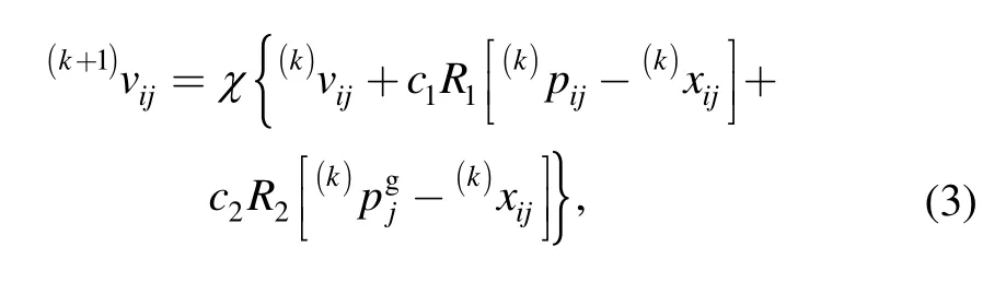
where χ is the constriction factor defined by

Commonly,both c1and c2are set to 2.05.Obviously,this PSO model is algebraically equivalent with the inertia weight model described in equation Eq.(2).However,in literature it is distinguished due to its theoretical properties that point out the explicit selection of its parameters.
3 Model of the Rotor/AMB System
AMBs consist of an array of electromagnets,sensors,a set of power amplifiers and a controller.They operate on the principle of active magnetic suspension.Fig.1 illustrates a most common radial AMB structure with four pole pairs,in which each AMB actuator consists of two pairs of electromagnets which operate in a differential driving mode.This means that one electromagnet in the pair is driven with the sum of the bias current i0and the control current(designated as ixin the x-direction and iyin the y-direction)and the opposite one with their difference[21].
Although rotations and transverse motions of the real rotor cannot be controlled by one pair of AMB electromagnets,the basic properties of a magnetic bearing control loop can easily be investigated using only one degree of freedom(one-axis)or two degrees of freedom(two-axis)rotor models.This implies that the rotor is reduced to a single concentrated mass suspended in the magnetic field,which is an appropriate simplification for a preliminary study.
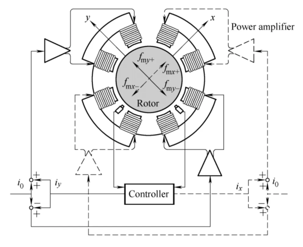
Fig.1.Cross-section of a typical radial AMB
Therefore,in this study two separate analyses are carried out.In the first,the rotor is modeled as a one degree of freedom system,i.e.as a SISO system.In the second,the interference among the x-and y-axes is additionally introduced and the rotor is modeled as a two degree of freedom system,i.e.as a 2×2 MIMO system.
3.1 One-axis AMB suspension system model
Fig.2 shows the block diagram of a one-axis rotor/AMB system in a feedback loop,where ymis the sensor output,u is the control signal(voltage)applied to the plant,i is the coil current and y is the actual rotor displacement.Each component of the system is briefly elaborated in the following subsections.
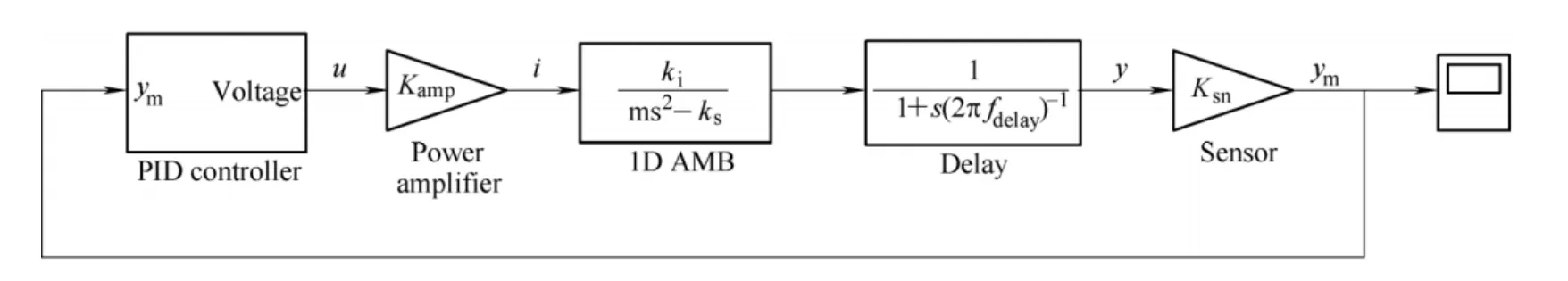
Fig.2.Block diagram of a one-axis rotor/AMB system in a feedback loop
3.1.1 Magnetic actuator,power amplifier and sensor models
For magnetic actuators of the differential type,the following dynamic equation of motion applies:
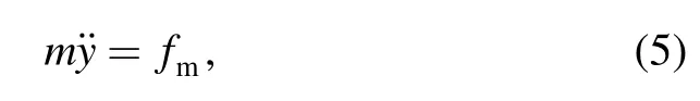
where fm=ksy+kii is the linearized magnetic force,using which Eq.(5)can be easily transformed into the transfer function form:
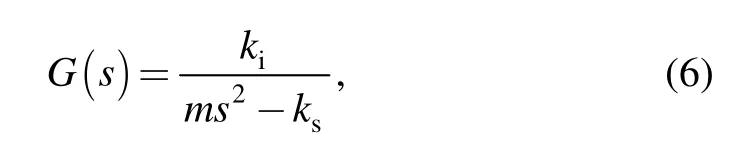
where kiis the force-current coefficient,ksis the negative force-displacement coefficient and m is the rotor mass.Power amplifiers and sensors are modeled as simple gains Kampand Ksn,respectively,since its dynamics can be neglected.
3.1.2 Delay model
In actual magnetic suspension systems,the phase lag delay is always present.It can be caused by many reasons,such as:iron losses in the actuator iron core,flux delay caused by eddy currents,voltage saturation in the current driver,limited sensor and power amplifier frequency response,the sampling period of the digital controller,etc.In order to simplify the analysis,but also to take into account such influences,all possible phase lags will be included in the form of a single first order transfer function

where fdelayis the cut-off frequency measured in hertz(Hz).
3.1.3 PID controller structures
Three PID controller structures will be examined.The first is the parallel PID controller structure(PID-P controller)whose mathematical representation is given as

where Kpis the proportional gain,Kintis the integral gain and Kdis the derivative gain.One disadvantage of this configuration is that a sudden change of the rotor position(and hence a large error e between the reference input r and the measured position ym)will cause the derivative term to become very large,causing large control signals as well.Accordingly,an alternative implementation is

where the proportional and derivative parts act on the measured value and not on the error,i.e.only the I-controller acts on the set point,giving an I-PD controller.The third controller is obtained as a series connection of the PD and PI controllers,giving a series PID structure(PID-S),whose model can be presented as follows:

In order to tune the presented controllers(PID-P,I-PD,PID-S)and to achieve the desired responses,they will be independently implemented and configured by using the PSO algorithms.

Fig.3.PID-P controller structure
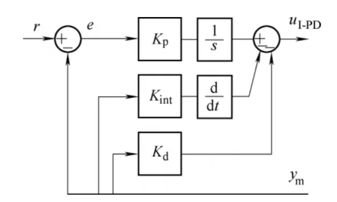
Fig.4.I-PD controller structure
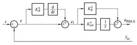
Fig.5.PID-S controller structure
3.2 Two-axis AMB suspension system model
The generated radial magnetic forces are mostly aligned in two perpendicular axes which usually coincide with the geometrical x and y axes.Under some circumstances(misalignment of the displacement sensor and the electromagnet,flux due to eddy currents,the gyroscopic effect,etc.)misalignment of the radial force can occur,i.e.the direction of the generated radial force can have an angular error.As a consequence,force interference between the two axes is induced.Fig.6 shows two perpendicular axes x and y and two radial magnetic forces fmxand fmyinclined by a small angle θ,wherefrom the total magnetic forces can be calculated as follows:
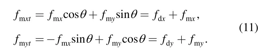
Due to the small value of angle θ,cosθ can be approximated by unity.The additional(interfering)forces caused by the angular error are designated as fdxand fdy.
Finally,dynamic equations of motion of a rotor suspended by linear magnetic actuators in xy-plane are
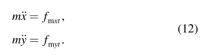

Fig.6.Angular error of the radial AMB force
4 Implementation of PID Controller Structures Tuned by PSO
Three PID controller structures tuned with LDW-PSO and CFA-PSO algorithms were developed for a magnetic suspension system.The algorithms are used to determine the three PID gains(Kp,Kint,Kd),independently for each of the controller structures.Therefore,a three dimensional search space is defined,in which each of the controller gains corresponds to one dimension,i.e.each particle in the search space represents a particular combination(Kp,Kint,Kd)for which a unique response can be obtained.
In the framework of PSO,the quantities that need to be initialized prior to the execution of the algorithm are the initial positions and velocities of each of the N particles in the population.In this study the initial combination of gains(Kp0,Kint0,Kd0)is generated as a set of random values within the interval[0,1].These values were then scaled with the corresponding magnitudes obtained from the Ziegler-Nichols tuning rules applied to one-axis AMB system.This procedure gives the following values:

The initial velocities are set to zero for all particles in all three dimensions.For the case of a two-axis magnetic suspension model the aforementioned procedure is extended with the additional controller(two PID controllers).It is assumed that the gains of both controllers are the same.
Evaluation of a given set of controller gains is achieved by simulating a unit step response of the resulting closed loop system.In order to obtain a measure of the transient response performance of the system,the integral of time multiplied by the absolute value of error(ITAE)is taken as the objective function as follows:

where p is the number of controllers(p=1 for a one-axis system and p=2 for a two-axis system)and T is the time of integration.The required PID gains minimize the objective function in the time domain,i.e.the performance indicators(overshoot,settling time,rise time and steady state error).
5 Simulation Results and Discussion
To identify the gains of the presented PID structures and to study the performances of the LDW-PSO and CFA-PSO algorithms the simulation experiments were carried out on the two AMB suspension systems.The input data for these systems are presented in Table 1.
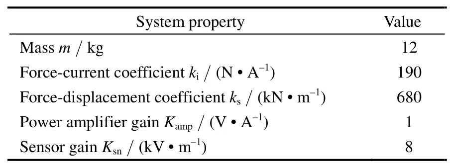
Table 1.Characteristics of the rotor/AMB system
The system delay is modeled by the cut-off frequency fdelay=500Hz.In order to ensure convergence,the maximum number of iterations kmaxis set to 200 for LDW-PSO and to 250 for CFA-PSO.Unit step is applied as a rotor position reference(r=1).The final time T is set to 0.1 s and each algorithm was repeated for 10 independent trials.In LDW-PSO,weighting factors c1and c2are defined as c1=c2=1 and w is linearly decreasing from wmax=1.2 to wmin=0.3.To study the performances of PID structures,the one-axis(example 1)and the two-axis AMB system(example 2)are investigated.
5.1 Example 1:One-axis rotor/AMB model
The one-axis rotor/AMB model is considered in this example.The best results,with respect to the transient response performances,among the 10 independent trials are registered and presented as follows.The convergence curves of the objective function are shown in Fig.7.The gain convergence curves for each of the PID structures are presented in Figs.8 and 9.Finally,the performance indicators in time domain are given in Table 2 and the corresponding unit step responses are illustrated in Fig.10.
5.2 Example 2:Two-axis rotor/AMB with interference
Analogous analyses are carried out for the two-axis rotor/AMB model including three PID structures.The angular error θ is defined as 5°.
Simulation results were repeated for 10 independent trials and LDW-PSO and CFA-PSO were employed.The convergence curves of the objective function are given in Fig.11.The PID gain convergence curves for each control structure are presented in Figs.12 and 13,while the corresponding unit step responses are illustrated in Figs.14 and 15.By examining the obtained results some general conclusions can be drawn.The PSO algorithms can be successfully applied,regardless of the controller structure and perform well in gain tuning of the presented systems.This means that various controller structures can be easily tuned using the presented PSO algorithms,which have shown ease of the tuning in case of both SISO and MIMO AMB systems.By analyzing the convergence curves it is noticed that PID gains converge more steadily and in a less number of iterations in the case of the LDW-PSO approach(Figs.8,12)then in the case of the CFA-PSO approach(Figs.9,13).Moreover,PSO is identified as a robust method in terms of its searching capabilities,computational efficiency and convergence properties.

Fig.7.Convergence curves of objective functions(example 1)
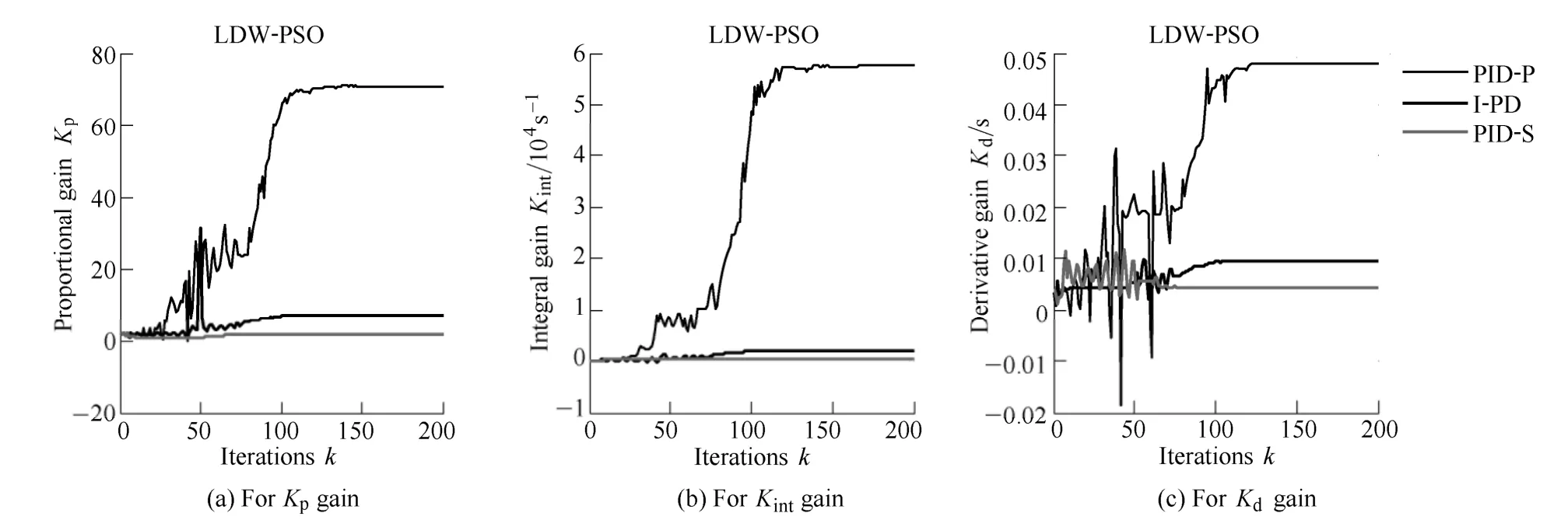
Fig.8.Convergence curves of the PID control gains for the LDW-PSO algorithm(example 1)

Fig.9.Convergence curves of the PID control gains for the CFA-PSO algorithm(example 1)
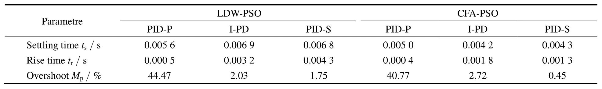
Table 2.Comparison of the obtained performance indicators in time domain(example 1:one-axis rotor/AMB model)

Fig.10.Comparison of the step responses(example 1)
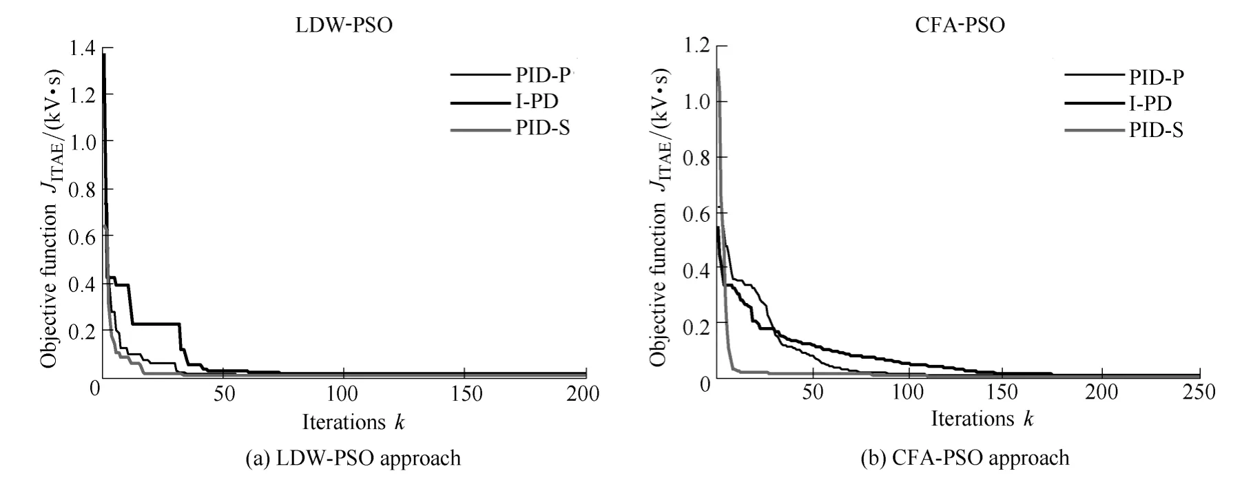
Fig.11.Convergence curves of objective functions(example 2)
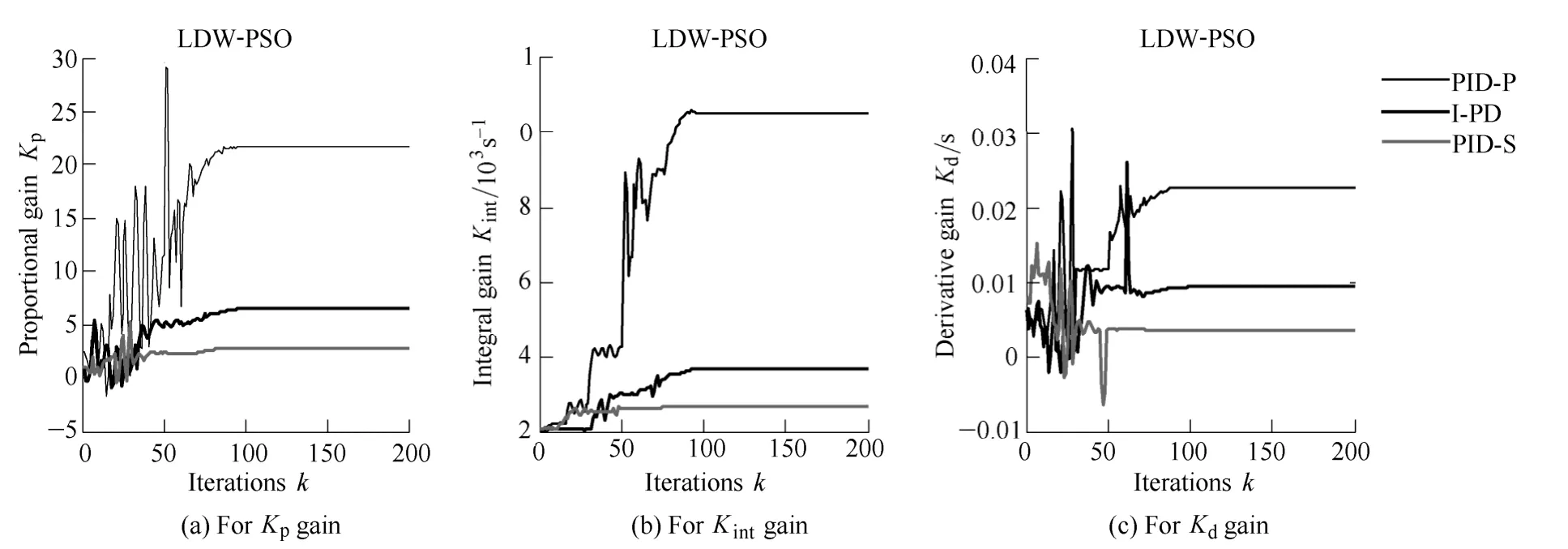
Fig.12.Convergence curves of the PID control gains for the LDW-PSO algorithm(example 2)

Fig.13.Convergence curves of the PID control gains for the CFA-PSO algorithm(example 2)
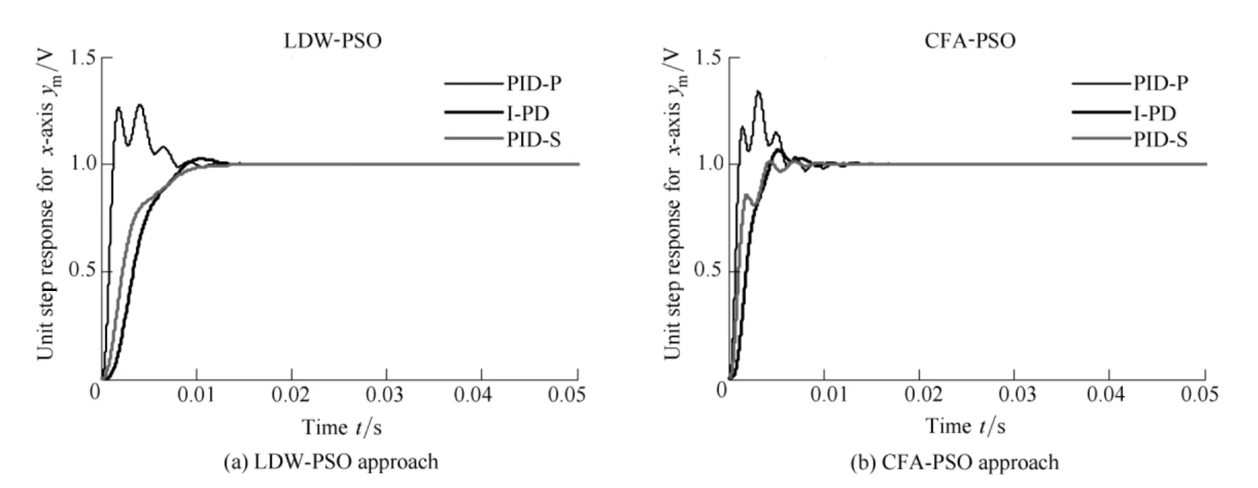
Fig.14.Comparison of the step responses along the x-axis(example 2)
Fig.15.Comparison of the step responses along the y-axis(example 2)
From Figs.7 and 11,the same tendency of the objective function can be observed in both examples.Although the rise time and the settling time is smaller when using the CFA-PSO approach,the LDW-PSO algorithm ensures faster convergence and almost aperiodic(i.e.non-oscillatory)response(Figs.10,14,15).
Regarding to the controller structure,the PID-P structure provides the undesirably large overshoot values in each of the considered cases,while the I-PD and PID-S structures perform almost equally well and ensure much better results in comparison with the PID-P controller.As expected,this is a direct consequence of the inherent properties of the implemented controller structures,which additionally proves the efficiency of the presented PSO approaches.
6 Conclusions
A comparative performance analysis of two PSO algorithms for PID controller tuning of a rotor/AMB system is presented.The two PSO algorithms,the LDW-PSO and the CFA-PSO,are independently implemented and tested for three PID structures(PID-P,I-PD and PID-S),for one-axis and two-axis rotor/AMB models.The PID controllers are designed considering minimization of the ITAE criterion.The main simulation conclusions are outlined as follows:
(1)The PSO algorithms show ease of the controller tuning in case of both SISO and MIMO rotor/AMB systems,which consider also the system delay and the interference among the horizontal and vertical rotor axes.
(2)PSO is identified as a robust method both in terms of its searching capabilities and computational efficiency.
(3)The CFA-PSO approach ensures faster rise time,while the LDW-PSO algorithm provides almost nonoscillatory system responses.
(4)ITAE objective function is proved to be suitable for the optimal design of PID controllers.
(5)Better performance of I-PD and PID-S controllers over PID-P controller is observed,what is in direct correlation with the nature of the implemented controller structure.
In future research,these investigations will be extended to more complex rotor/AMB systems which involve rigid and,preferably,flexible rotors.
[1]LEI S,PALAZZOLO A.Control of flexible rotor systems with active magnetic bearings[J].Journal of Sound and Vibration,2008,314:19–38.
[2]ŠTIMAC G,BRAUT S,ŽIGULIĆ R.Vibration suppression of flexible rotor using active magnetic bearings(AMB)[J].Transactions of Famena,2011,35:27–38.
[3]ASTRÖM K J,HÄGGLUND T.The future of PID control[J].Control Engineering Practice,2001,9:1163–1175.
[4]ZIEGLER J B,NICHOLS N B.Optimum settings for PID controllers[J].Transactions of ASME,1942,64:759–768.
[5]ZHAO Z Y,TOMIZUKA M.Fuzzy gain scheduling of PID controllers[J].IEEE Transactions on Systems,Man,and Cybernetics,1993,23:1392–1398.
[6]AL-ODIENAT A I,AL-LAWAMA A A.The advantages of PID fuzzy controllers over the conventional types[J].American Journal of Applied Sciences,2008,5:653–658.
[7]CHEN K Y,TUNG P C,TSAI M T,FAN Y H.A self-tuning fuzzy PID-type controller design for unbalance compensation in an active magnetic bearing[J].Expert Systems with Applications,2009,36:8560–8570.
[8]CHEN H C,CHANG S H.Genetic algorithms based optimization design of a PID controller for an active magnetic bearing[J].International Journal of Computer Science and Network Security,2006,6:95–99.
[9]KHANDANI K,JALALI A A.PSO based optimal fractional PID controller design for an active magnetic bearing suspension system[C]//Proceedings of 18th Annual International Conference on Mechanical Engineering,Iran,Teheran,May 11–13,2010:1–6.
[10]KIM T H,MARUTA I,SUGIE T.Robust PID controller tuning based on the constrained particle swarm optimization[J].Automatica,2008,44:1104–1110.
[11]CHANG W D,SHIH S P.PID controller design of nonlinear systems using an improved particle swarm optimization approach[J].Communications in Nonlinear Science and Numerical Simulation,2010,15:3632–3639.
[12]FANG H,CHEN L,SHEN Z.Application of an improved PSO algorithm to optimal tuning of PID gains for water turbine governor[J].Energy Conversion and Management,2011,52:1763–1770.
[13]MENHAS M I,WANG L,FEI M,et al.Comparative performance analysis of various binary coded PSO algorithms in multivariable PID controller design[J].Expert Systems with Applications,2012,39:4390–4401.
[14]CHIHA I,LIOUANE N,BORNE P.Tuning PID controller using multiobjective ant colony optimization[J].Applied Computational Intelligence and Soft Computing,2012:1–7.
[15]KENNEDY J,EBERHART R.Particle swarm optimization[C]//Proceedings of IEEE International Conference on Neural Network,Part IV,Perth,Australia,1995:1942–1948.
[16]PARSOPOULOS K E,VRAHATIS M N.Particle swarm optimization and intelligence:Advances and Applications[M].New York:Information Science Reference,2010.
[17]XU H,CHEN G.An intelligent fault identification method of rolling bearings based on LSSVM optimized by improved PSO[J].Mechanical Systems and Signal Processing,2012,35:167–175.
[18]LIN Y L,CHANG W D,HSIEG J G.A particle swarm optimization approach to nonlinear rational filter modeling[J].Expert Systems with Applications,2008,34:1194–1199.
[19]SHI Y,EBERHART R C.A modified particle swarm optimizer[C]//Proceedings of the IEEE International Conference on Evolutionary Computation,Anchorage,USA,1998:69–73.
[20]CLERC M,KENNEDY J.The particle swarm:explosion,stability and convergence in a multi-dimensional complex space[J].IEEE Transactions on Evolution Computation,2004,8:204–210.
[21]SCHWEITZER G,MASLEN Eric H.Magnetic bearings:theory,design and application to rotating machinery[M].New York:Springer,2009.