CCCDTA的零-镜实现及其对正交振荡器综合的应用*
李永安
(咸阳师范学院物理与电子工程学院,陕西咸阳712000)
Recently,a symbolic framework for systematic synthesis of linear active circuit was presented in Ref.[1-6].This method,called NAME(Nodal Admittance Matrix Expansion),is very useful in generation of a series of novel circuits.Fortunately,the literature on current conveyor(CCⅡ)and inverting current convey(ICCⅡ)based gyrators[7],oscillators[8]and filters[9]has explained this viewpoint well.However,most of the circuits mentioned in earlier works are based on the CCⅡor ICCⅡ.So far,it has not been found that NAME is generalized to other active devices,for instance,current differencing transconductance amplifier(CDTA),current-controlled current differencing transconductance amplifier(CCCDTA),etc.On the other hand,CDTA was reported in 2003[10-11].Unfortunately,a CDTA has only one parameter electronically controlled,which is not desirable for the circuit designers.Recently published current-controlled currentdifferencing transconductance amplifier(CCCDTA)is a versatile component in the realization of a class of analog signal processing circuits,especially filters and oscillators.Since the parasitic resistances at two current input ports can be electronically controlled through turning biasing current,the circuit designers have greatversatility in generating new circuits and controlling their properties.Therefore,the current-mode oscillators[12]and universalfilters[13-14]using CCCDTAshave found wide applications in electronics community.However,the design methods for the circuits using CDTAs or CCCDTAs are short of the systematic characteristic.
The paper aims at using NAME to realize currentmode oscillators employing CCCDTAs.First,the nullormirror descriptions for CCCDTA are given,which possess four different forms.Second,on the ground of the classⅡA and B of the NAM in Ref.[8]and using NAME,eight alternative NAM equations are obtained,resulting in eight alternative realizations of oscillators.The last,based on the eightcircuitmodes,two alternative quadrature oscillators employing CCCDTAs are received.Having used canonic number of components and grounded capacitors,the circuits are easy to be integrated and the condition for oscillation and the frequency of oscillation can be tuned electronically through tuning bias currents of the CCCDTAs.EWB simulations are included to verify the workability of the proposed circuit.
1 Four Nullor-Mirror Descriptions for CCCDTA
It is known that the terminal relation of CCCDTA can be characterized by the following set of equations:

Here,the parasitic resistances at thepandninput terminals,RpandRn,can be expressed to be

For a CCCDTA implemented with bipolar technology,the transconductance gain of the CCCDTA,gm,can be expressed

Here,IB0andIB1are the DC bias currents of the CCCDTA andVTis the thermal voltage.
The nullor-mirror elements,so called pathological elements,play an important role in the circuit theory and the application[1-2]. Although the nullor-mirror elements,namely nullor elements and mirror elements,have successfully described CCⅡand ICCⅡ,They have not been able to represent other active elements,for example CDTA or CCCDTA.With this background,according to the terminal voltages and currents constraints for the nullor-mirror elements[7]as well as the terminal relation of the CCCDTA,the nullor-mirror elements representations of the CCCDTA are firstly presented,as shown in Fig.1.

Fig.1 Four equivalent realizations of CCCDTA
It should be noted that besides same current differential unit,four equivalent realizations have two characteristics:one is a grounded nullator,the other is the current tunability of parameters(Rp,Rn,andgm).It can also be seen that the nullor-mirror descriptions for a CCCDTA are much more complex than a CCⅡor an ICCⅡ,This is due to the fact that a CCCDTA,consisted of a OTA and two CCCⅡ,has more complex structure than a CCⅡor an ICCⅡ.
2 Equivalent Realizations of Two-Type Oscillators
There are two types of oscillator that can be achieved by using CCCDTAs.The NAM for class A is given in Ref.[8]by

The NAM for classBis also given in Ref.[10]by


Here,C1is the grounded capacitor connected with node 1,C2the grounded capacitor connected with node 2.
Eq.(6)~Eq.(7)show that the frequency of oscillation can be turned by adjustingG2without affecting the condition for oscillation,which can also be tuned by adjustingG1without affecting the oscillation frequency.This means that the oscillation condition and the oscillation frequency of the oscillators can be tuned independently.
Here,G3is the floating conductance shared a node with one of the capacitors;G2andG1are the grounded conductances,respectively.
The oscillation condition and oscillation frequency for two types of oscillator can be given as
2.1 Class A oscillator
Since two types of the oscillator contain five nodes,the first step in the NAME is to add two blank rows and columns to Eq.(4).Then,following successive NAME steps,the first alternative NAME can be obtained as follows[8]:

Eq.(8)shows thatG1is the grounded conductance connecting node 4,G2is the grounded conductance connecting node 3,andG3is the floating conductance between node 1 and node 5.Inserting the capacitors at nodes 1 and 2,the above equation is realized in the Fig.6(a)of Ref.[8].
The second alternative NAME can be obtained,as shown in the Eq.(22)of Ref.[8].The corresponding equivalent realization is given in the Fig.6(b)of Ref.[8].
The third alternative NAME can be obtained,as shown in the Eq.(23)of Ref.[8].The corresponding equivalent realization is given in the Fig.6(c)of Ref.[8].
The fourth alternative NAME can be obtained,as shown in the Eq.(24)of Ref.[8].The corresponding equivalent realization is given in the Fig.6(d)of Ref.[8].
It should be noted that a nullator must be used to link the fifth column to ground in the above expansion steps so that four nullor-mirror realizations for class A oscillator can be achieved by the CCCDTAs,respectively.A-gain,this is also suitable for class B oscillator.
2.2 Class B oscillator
Similarly,starting from Eq.(5)and following successive NAME steps,the four alternative NAMEs can be obtained,as shown in the Eq.(25)~ Eq.(28)of Ref.[8].The corresponding equivalent realization is given in the Fig.7(a)~7(d)of Ref.[8].
3 Realization of Two CCCDTA Based Oscillators
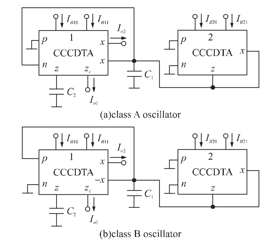
From Fig.1 and Fig.6(a)~6(d)of Ref.[8],four alternative realizations of class A oscillator can be equivalent as Fig.2(a).From Fig.1 and Fig.7(a)~7(d)of Ref.[8],four alternative realizations of class B oscillator can also be equivalent as Fig.2(b),this means eight alternative realizations only yields two equivalent circuits using two CCCDTAs.It should be noted that the current differencing unit of CCCDTA 2 in Fig.2(a)and Fig.2(b)could be deleted to get the simplest circuits,thus,in fact,the CCCDTA 2 is served as an OTA.
It is seen that the circuit of Fig.2(b)is the same as Fig.26 in Ref.[14],but the circuit of Fig.2(a)is new.
If anotherzcterminal andxterminal are added to the CCCDTA 1 in Fig.2(a)and Fig.2(b),respectively.Two quadrature oscillators with high output impedance are realized.From Eq.(2)~Eq.(3)and Eq.(6)~Eq.(7),the oscillation condition and oscillation frequency for two oscillators can be given as,respectively,

On the other hand,from routine analysis of the circuit in Fig.2(a)or Fig.2(b),the characteristic equation of the oscillator is easily obtained:

Therefore,the oscillation condition and oscillation frequency for the oscillators are the same as Eq.(6)~Eq.(7).Although this method can also implemented the circuits of Fig.2(a)and Fig.2(b),it is lack of systematic characteristic.

Fig.2 CCCDTA based realizations
From the circuit in Fig.2(a)or Fig.2(b),for sinusoidal steady state,the current transfer function fromIo1toIo2is

Eq.(9)shows that adjustingIB21can electronically turn the condition for oscillation,whereas Eq.(10)indicates that trimmingIB11can separately adjusted the frequency of oscillation.This means that the circuits provide the attractive feature of independent control of the oscillation frequency and the oscillation condition.From Eq.(12),however,two output current signals of the oscillators do not equal in amplitude.
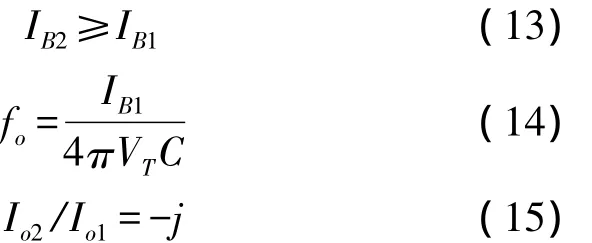
In order to obtain two orthogonal current signals with equal-amplitude,let[15]IB11=4IB10=IB1,IB21=IB2,C1=C2=C.Eq.(9)~Eq.(10)and Eq.(12)simplify to

The above equations show that two oscillators are able to provide two orthogonal current signals with equal-amplitude,but the control of the oscillation frequency and the oscillation condition is dependent.The oscillators can be tuned as follows:(a)adjustIB1for the desired value offo;(b)adjustIB2to meet the oscillation condition.Anyway,two CCCDTA-based current-mode quadrature sinusoidal oscillators with high output impedance are realized.
All the active and passive sensitivities of the oscillators can be expressed as

Eq.(16)shows that active and passivefosensitivities are less than unity in magnitude and hence the circuits exhibit a good sensitivity performance.
On the other hand,the CCCDTA 2 in Fig.2(a)and Fig.2(b)simulates a negative resistance.Consequently,the negative resistance releases power,while the positive resistance,theRnof the CCCDTA 1,absorbs power.Note,however,the oscillation condition,Eq.(6),is satisfied only if the releasing power is greater than or equals the absorbing one,namelyV2G1≥V2/Rn=V2G3.This is just the oscillation condition given by(6).
4 Simulation Results
In order to test the performances of the derived circuits,the sub-circuit for CCCDTA was created on transistor PR100N and NR100N by ELECTRONICS WORKBENCH software[10],and then Fig.2(a)was created.Finally,the Fig.2(a)circuit was simulated with ±1.5 V power supplies,C1=C2=10 nF,IB11=4IB10=IB1=260 μA,andIB2=265 μA.The simulation results are shown in Fig.3.This shows that the circuit really created a quadrature sinusoidal oscillation.Using Eq.(14)yieldsthedesign valueforoscillation frequencyfo=79.62 kHz;using the pointer in EWB5.0 yields the actual value for oscillation frequencyf'o=76.63 kHz,so the deviation for oscillation frequency is

It is noted that the results of circuit simulations are in agreement with theory.

Fig.3 The steady-state waveforms for proposed circuit when C1=C2=10 nF,IB1=260 μA,IB2=265 μA,RL=1 kΩ.
5 Conclusions
This is the first paper in which the use of the NAME method in the synthesis of CCCDTA based oscillators is considered.The main feature of the paper is making use of systematic design method to obtain novel circuit.In addition,the new derived oscillators enjoy the following features:
(1)Current control of the frequency and the condition of oscillation through adjusting the bias currents of the CCCDTAs;
(2)Use of canonic number of components and grounded capacitors;
(3)High output impedances;
(4)Low passive and active sensitivities.
The main drawback of the circuits is that two output current signals of the oscillators will not equal in amplitude if the independent control of oscillation condition and oscillation frequency are desirable;otherwise,the condition for oscillation and the frequency of oscillation will be tuned dependently if two outputcurrentsignalsofthe oscillatorsare desirable to be equal in amplitude.
Acknowledgement
This work is supported by the Natural Science Foundation of Shaanxi Province(Grant No.2012JM8017)and the Scientific Research Program Funded by Shaanxi Provincial Education Department,China(Program No.12JK0496).The author would also like to thank the anonymous reviewers for their suggestions.
[1]Haigh D G,Clarke T J W,Radmore P M.Symbolic Framework for Linear Active Circuits Based on Port Equivalence Using Limit Variables[J].IEEE Transactions on Circuits and Systems I,2006,53(9):2011-2024.
[2]Haigh D G.A Method of Transformation from Symbolic Transfer Function to Active-RC Circuit by Admittance Matrix Expansion[J].IEEE Transactions on Circuits and Systems I,2006,53(12):2715-2728.
[3]Haigh D G,Tan F Q,Papavassiliou C.Systematic Synthesis of Active-RC Circuit Building Blocks[J].Analog Integrated Circuits and Signal Processing,2005,43(3):297-315
[4]Haigh D G,Radmore P M.Admittance Matrix Models for the Nullor Using Limit Variables and Their Application to Circuit Design[J].IEEE Transactions on Circuits and Systems I,2006,53(10):2214-2223.
[5]Soliman A M.Transformation of Oscillators Using op Amps,Unity Gain Cells and CFOA[J].Analog Integrated Circuits and Signal Processing,2010,65(1):105-114.
[6]Soliman A M,Saad R A.The Voltage Mirror-Current Mirror Pair as a Universal Element[J].International Journal of Circuit Theory and Applications,2010,38(8):787-795.
[7]Zhao Y,Wang W D.A Programmable Voltage Mode Multifunction Filter and Programmable Instrumentation Amplifier Based on CMOS CCDVCCⅡ[J].Chinese Journal of Electron Devices,2011,34(1):53-56.
[8]Soliman A M.Generation of Current Conveyor Based Oscillators Using Nodal Admittance Matrix Expansion[J].Analog Integrated Circuits and Signal Processing,2010,65(1):43-59.
[9]Zhao Y,Wang W D.A New Wide Linear Range Differential Voltage Current Conveyor and Its Application[J].Chinese Journal of Electron Devices,2011,34(2):179-182.
[10]Lahiri A.New Current-Mode Quadrature Oscillators Using CDTA[J].IEICE Electronics Express,2009,6(3):135-140.
[11]Li Y A.A Modified CDTA(MCDTA)and Its Applications:Designing Current-Mode Sixth-Order Elliptic Band-Pass Filter[J].Circuits,Systems,and Signal Processing,2011,30(6):1383-1390
[12]Li Y A.A New Single MCCCDTA Based Wien-Bridge Oscillator with AGC[J].AEU-International Journal of Electronics and Communications,2012,66(2):153-156.
[13]Tangsrirat W,Surakampontorn W.Systematic Realization of Cascadable Current-Mode Filters Using Current Differencing Transconductance Amplifiers[J].Frequenz,2006,60(11-12):241-245.
[14]Li Y A.Current-Mode Sixth-Order Elliptic Band-Pass Filter Using MCDTAs[J].Radioengineering,2011,20(3):645-649.
[15]Li Y A.Electronically Tunable Current-Mode Quadrature Oscillator U-sing Single MCDTA[J].Radioengineering,2010,19(4):667-671.

