Three-Dimensional Sono-elasticity Analysis of Floating Bodies
ZOU Ming-song,WU You-sheng,YE Yong-lin,SUN Jian-gang,QI Li-bo
(China Ship Scientific Research Center,Wuxi 214082,China)
1 Introduction
In the analyses of wave loads and responses of a floating body in the sea,the fluid is assumed incompressible.When the acoustic responses of ship structures are to be investigated,the FEM and BEM were applied to describe the acoustic radiation phenomena of elastic structures for several decades[4-8].The acoustic power radiated by a pulsating sphere in 3-D half space was investigated[9].However the free surface and the forward speed effects on the acoustic radiations of a traveling structure have not been sufficiently investigated.The present work extends the theory of Ref.[1]and the numerical methods employed in Refs.[10-11]to include the effect of fluid compressibility in the analysis of fluid-structure interactions,by using the Green’s function for ideal compressible fluid.The acoustic radiations of the ship structure excited by the onboard machinery or the incident acoustic wave may then be predicted with the inclusion of the free surface and the forward speed effect.A spherical shell in infinite fluid domain was predicted and compared with analytical solutions.To eliminate the irregular frequencies appeared in the numerical analyses of fluid-structure interaction problems,a method of introducing an imaginary closed impedance-surface inside the wetted surface of the structure is proposed.The numerical predictions of machinery-excited acoustic radiations of a submerged double-skin ring-stiffened cylindrical hull is illustrated.
2 The linear sono-elasticity theory of ships in frequency domain
The fluid motion and responses of a floating body are defined in an equilibrium coordinate system Oxyz[1,11].The structure is assumed to be linear with small motions and distortions about its equilibrium position.The displacement at any point of the structure may be expressed as the superposition of the principal modes of the dry structure:

When a floating body is either slender,thin,flat,or moves slowly,the non-uniform perturbations of the steady flow due to the forward movement of the floating body are small and negligible,and Eq.3 is reduced to.The interface boundary condition on the floating body’s mean wetted surfacemay be simplified as[1,11]


The Green function satisfying Eq.6 is

where P=(x,y,z)and Q=(ξ,η,ζ)are the field and the source points,respectively.k=ω/c0is the wave number,andThe radiation potentials can be expressed as integrals over the mean wetted surfaceand waterline

The generalized equations of motion for the sono-elastic responses of the floating body structure may be represented in the matrix form:

where[a],[b]and[c]are matrices of generalized modal intertial,modal damping and modal stiffness of the dry structure.is the vector of principal coordinates.is the generalized force vector.[A],[B]and[C]are the matrices of generalized fluid inertia,damping and restoring coefficients,respectively.


3 Verification of the present method
To verify the present method and the code,the acoustic pressure field radiated by an elastic spherical shell,which is excited by a sinusoidal concentrated force F with unit amplitude,as shown in Fig.1,is calculated.The shell is made of steel,with the radius 0.5 m,thickness 1 mm and damping ratio 0.01.The numerical results for the spherical shell located far below the water surface are compared with the analytical solution for the case of infinite fluid domain,which is of the form[12]


Fig.1 Spherical shell and coordinate system
where Unris the amplitude of the n-th modal displacement in radial direction,is the n-th sphere Hankel function of the second kind,Pnis the n-th Legendre polynomial,and R is the radius.
The comparison is described by the source level of the acoustic radiation,defined as

where the acoustic pressure at the observation position(r,θ)is transferred to r=1 m with the reference pressure p0=1 μPa.Fig.2 illustrates the comparisons of Lpfor four observation positions(r=1 m,100 m and θ=π/2,π).Evidently the numerical results and the analytical solutions are nearly coincident.The slight difference is caused by the numerical discretization.

Fig.2 Comparison of the acoustic radiations of the spherical shell

Fig.3 The impedance-surface in the inner domain
4 Elimination of the irregular frequencies
4.1 Method of eliminating irregular frequencies
The occurance of irreqular frequencies in the analysis of a wave-body or fluid-structure interaction problem greatly reduces the precision of predictions[13-17].This is a kind of mathematical phenomena representing one of the numerical solution regions of the corresponding boundary integral equations,which are not the physical answers in the actual fluid domain.To eliminate the irregular frequencies in the prediction of acoustic responses of a structure in ideal acoustic medium τe,it is proposed in this paper to place a closed impedance-surface Si2in the imaginary inner fluid domain τiinside the wetted surface Se(Fig.3).Assuming φi,φeare the velocity potentials defined in the inner and the outer fluid domain,respectively,and ne,niare the unit normal vectors of Seand Si1∪Si2,respectively,the interface boundary conditions on Si2and Semay be written as

where pni2is the pressure on Si2.uni2and ZSare the dis-placement and mechanical impedance of Si2in nidirection,respectively.uneis the displacement of Sein nedirection.The integral equations for solving the source strength σ(Q)in the outer domain and the unkown displacement uni2are as follows:

Insertion of the imaginary impedance-surface inside the wetted surface of the body not only moves the oscilation frequencies of the inner fluid domain to the upper band by changing its volume,and also absorbs the oscillation energy of the inner flow.This enables the elimination or removal of the irregular frequencies.
4.2 Example of eliminating irregular frequencies
The effectiveness of the imaginary impedancesurface in eliminating the irregular frequencies in the acoustic radiation predictions of the spheric shell(Fig.1)is exhibited in Fig.4.The impedancesurface is the cubic box with the side length b=0.4 m,and impedance ZS=ρ0c0.The center of the cubic box coincides with the center of the spheric shell.The results do not have the irregular frequency effect showing good agreement with the analytical solution of Eq.13 with n=7.

Fig.4 Elimination of the irregular frequencies in the acoustic radiation predictions of the spherical shell(r=100 m,θ=π)

Fig.5 A submerged ring-stiffened double-skin cylindrical hull
5 Acoustic responses of a structure containing multiply-disconnected fluid regions
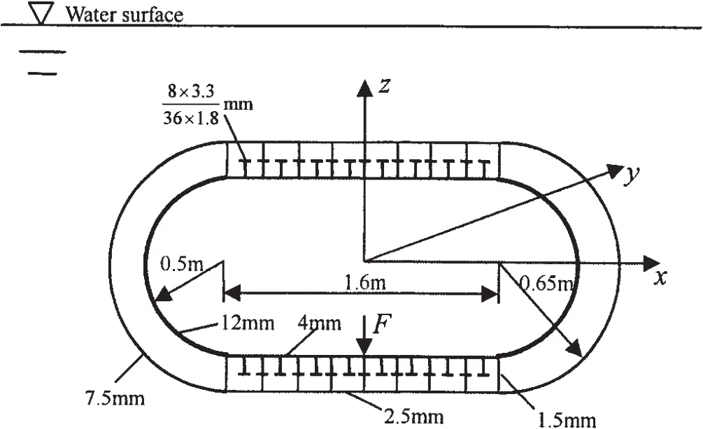
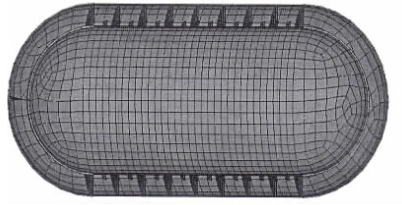
The present method and computer code may be used to predict the acoustic responses of a floating or submerged structure.As an example,the machinery excited acoustic radiations in near and far field of a submerged doubleskin ring-stiffened cylindrical hull are calculated.Water is filled in between the outer and the inner shells,therefore there exist two disconnected fluid regions.The structure is excited by a concentrated harmonic force F with unit amplitude.The dimensional drawing of the structure,the acting position of the excitating force,and the coordinate system are described in Fig.5.The finite element model of the structure and one of the principal modes of the dry structure are shown in Fig.6 and Fig.7.

Fig.6 The finite element model of the structure

Fig.7 One of the principal modes of the dry structure
5.1 The influence of the submerging depth on the acoustic radiation of the cylindrical hull
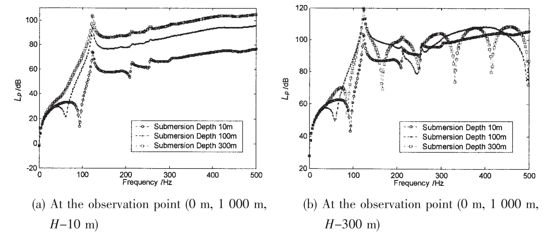
The source levels of the acoustic radiations(Eq.14)of the cylindrical hull submerged in different depth are predicted at different observation positions.Fig.8 exhibits the results calculated at two observation positions of(x,y,z)=(0 m,1 000 m,H-10 m)and(0 m,1 000 m,H-300 m),for the hull with three submerging depth H=10 m,100 m and 300 m.It shows that the submerging depth has great influence on the far-field radiation pressure or the source level.At the observation position only 10 m below the water surface,the predicted source levels of the cylindrical hull excited by the same concentrated harmonic force,but submerged in different depth will be different as shown in Fig.8(a).It seems that the free surface has the relaxation effect on the acoustic pressure.Fig.8(b)shows that at the position 300 m under the water surface,frequency variations of the calculated source levels follow the similar trands,however showing different fluctuation behaviours.

Fig.8 Influence of submerging depth on the acoustic radiations of the double-skin cylindrical hull
5.2 The distribution of the radiation pressure in near and far field
In infinite fluid domain,neglecting the free surface effect,the acoustic radiations of the hull calculated at five different frequencies 25 Hz,125 Hz,225 Hz,325 Hz,and 425 Hz as the observation point moving along the x-and y-directions respectively are plotted in Fig.9.

Fig.9 Variations of the calculated source levels with regard to the distance between the observation point and the gravity center of the cylindrical hull
6 Conclusions
The three-dimensional hydroelasticity theory[1-3]was extended to include the effect of fluid compressibility by replacing the translating-pulsating source Green’s function for incompressible fluid with that for ideal compressible fluid.Since the forward speed of a marine structure is usually much smaller than the sound speed in the water,in the sono-elastic analysis the free surface boundary condition may be greatly simplified.
To eliminate the irregular frequencies,which might appear in the boundary element analyses of sono-elasticity problems due to the cavity oscillations of the‘inner fluid domain’inside the wetted surface of the structure,an imaginary impedance-surface method is introduced.Its mechanism of removing the irregular frequencies is discussed,and its effectiveness is illustrated by the example of the spherical shell.
To examine the influence of the submerging depth of the structure on its acoustic radiations and the differences of the calculated radiation pressures or the source levels in the near and far field,the machinery excited acoustic radiations of a submerged double-skin ringstiffened cylindrical hull with two disconnected fluid regions are predicted and illustrated.It shows that the frequency variations of the self-noise in the near field are quite different from those of the radiation noise in the far field.It is also concluded that the source levels of a harmonic acoustic radiation calculated at the distances longer than the wave length may reach a constant value,and the spreading of the radiation noise in the far field keeps its directional characteristics.The present method may be used to better investigate the acoustic radiation phenomena of a marine structure in water.
[1]Wu Y S.Hydroelasticity of floating bodies[D].Ph.D.thesis.London:Brunel University,1984.
[2]Bishop R E D,Price W G,Wu Y S.A general linear hydroelasticity theory of floating structures moving in a seaway[J].Phil.Trans.Royal Soc.London,1986,A316:375-426.
[3]Du S X,Wu Y S.The effect of forward speed on the hydroelastic behaviours of ship structures[C]//In:Proc.of PRADS'98.Hague,The Netherlands,1998:597-603.
[4]Chen L H,Schweikert D G.Sound radiation from an arbitrary body[J].J Acoust.Soc.Am.,1963,35:1626-1632.
[5]McCormick J M,Baron M L.Sound radiation from submerged cylindrical shells of finite length[J].ASME Trns.,Ser.B.,1965,87:393-405.
[6]Zhang J T,He Z Y.Study of sound radiation of arbitrary revolution elastic shells dense medium excited by force[C]//4th,Int.Con.of Int.Maritime Association of East in Mediterrenean,Varna,Bulgarian,1987.
[7]Zhu X Q.Sound generation from a moving shell[C]//Proc of Int Symp on Shipboard Acoustics.Holland,1986.
[8]Shen S G,Li Q H,et al.Hydroelastic analysis of sound radiation from a stiffened shell of revolution[J].Shipbuilding of China,1992,117(2):53-62.
[9]Li S,Zhao D Y.Research on acoustic radiation in a three-dimensional half space[J].Journal of Ship Mechanics,2004,8(1):106-112.
[10]Wu Y S,Du S X.Effects of forward speed and steady flow on hydroelastic behaviour of travelling ships[J].Shipbuilding of China,Supplement of 1998:90-99.
[11]Du S X,Wu Y S,Price W G.Forward speed effect on the structure responses of a ship travelling in waves[C].Hydroelasticity in Marine Technology.Kashiwagi et al.(eds),Yomei Printing Cooperative Society,1998:401-410.
[12]He Z Y.Structural vibration and acoustic radiation[M].Harbin:Harbin Engineering University Press,2001:105-110.
[13]Ohmatsu S.On the irregular frequencies in the theory of oscillating bodies in a free surface[R].Paper of Ship Res Inst,1975,No.48.
[14]Miao G P,Liu Y Z.Notes on irregular frequencies[J].Journal of Hydrodynamics,1985(1):71-81.
[15]Lee C H,Sclavounous P D.Removing the irregular frequencies from integral equations in wave-body interactions[J].J Fluid Mech,1989,207:393-418.
[16]Zhu X.Removal of irregular frequencies of the boundary integral equation[R].MS Thesis.Department of Ocean Engineering,MIT,1994.
[17]Duan W Y,He W Z.A boundary element method for removing the effects of irregular frequency in solving the hydrodynamic coefficients[J].Journal of Hydrodynamics,2002,Ser A,17(2):156-161.
- 船舶力学的其它文章
- Transient Dynamic Analysis of Towed Low-tension Cable with Experimental Verification
- Characteristics of the Severe Slugging under Different Gas-Liquid Physical Parameters
- Research on Interaction between a Large Underwater Carrier and a Mini-underwater Vehicle
- Washes Produced by High Speed Displacement Ships in Shallow Water:Prediction vs Measurements
- Application of the Loading Inherent Subspace Scaling Method on the Whipping Responses Test of a Surface Ship to Underwater Explosions
- Research on Multiple Excitations Inversion-oscillations

