Research on Interaction between a Large Underwater Carrier and a Mini-underwater Vehicle
SU Yu-min,JU Lei,YU Xian-zhao,CUI Tong,YAN Dai-jun
(1.State Key Laboratory of Autonomous Underwater Vehicle,Harbin Engineering University,Harbin 150001,China;2.The 714 Institute of CSIC,Beijing 100000,China;3.China Ship Scientific Research Center,Wuxi 214082,China)
1 Introduction
Research on forces and flow features to relative motion between bodies has a broad prospect in many engineering field.Boundary element method was mainly used to simulate the calculation before.At present,dynamic mesh and remesh methods are applied in computational fluid dynamics techniques.But how to figure out the mesh deformation and ensure the mesh quality is the key to calculating the results accurately.
Xie Nan et al[1]predicted the hydrodynamic interaction between two bodies floating in waves based on linear 3-D potential theary.Pang Yongjie et al[2]adopted boundary element method to compute the hydrodynamic forces acting on two underwater vehicles when they are closing to each other and the curves of hydrodynamic force coefficients vs the distance between two underwater vehicles have been given.A new computing method-equivalent extending body method has been proposed for computing interaction forces between multiple bodies by Zeng Yifei et al[3].Cheng Li et al[4-6]have conducted detailed research in the area of hydrodynamic interactions between underwater bodies.Numerical and experimental research was performed on two-dimensional Rankine oval-wall hydrodynamic interactions using a simplified algorithm based on surface source and middle camber vortex distribution by Cheng Li et al[7].Choosing different velocities,attack angles,and wall clearances,the forces and moments exerted on a Rankine model were measured,from which the changing rule of aft flow separation point was drawn.Two kinds of blunt-end bodies including a 3D Rankine ovoid and a 3D flat ovoid moving parallel to a plane wall have been selected to calculate the interacting forces by nonviscous method and viscous CFD method by Cheng Li et al[8]and the influences of gap ratio,Reynolds number and flat degree of body surface on interacting forces have also been analyzed.
Although very few researches on interaction between underwater objects were made and most of them were based on boundary element method without taking viscosity into account,some similar research methods could be used for reference,especially the mesh regeneration noted by Liao Guojun et al[9].A methodology is developed to simulate unsteady flows around multi-body in relative motion by Guo Zheng et al[10-11]and compute the trajectory determined by this flow field.Cavallo et al[12-17]adopted unstructured mesh adaptation method to solve the mesh deformation and modification for the moving bodies and ensured the mesh quality.The multi-body separation has been predicted precisely.Unstructured dynamic mesh has been used for large movement and deformation by Murayama et al[18].Nathan et al[19]summarized forces and flow features for moving objects and discussed the parallel computing of overset grids for aerodynamic problems.A methodology has been presented for the simulation of flow past bodies in relative motion using a generalized grid-based overset framework by Koomullil et al[20].A rigid body simulator has been developed to predict the trajectory of moving bodies.Windtunnel experiments on a pair of generic slender bodies placed in parallel in the longitudinal direction have been described to study the interaction force by Weihs et al[21].Alexander et al[22]adopted theoretical solutions and computational fluid dynamics methods to predict lift interference between two bodies in supersonic flow and compared the merits and demerits.
2 Geometry,meshing technique,and boundary conditions
Forces between two-dimensional object with semi-circular stem and streamlined rear parts and wall were studied.Major specifications of the underwater vehicle are as follows:L=1.5 m,D=0.214 m.The grid reference coordinate system of calculation model of the underwater vehicle is shown in Fig.1.The underwater vehicle is axisymmetric along the X-axis and located at d above the wall.The stem is at 0.655 m from Y-axis.The total elements are about 0.04 million.

Fig.1 Grid reference coordinate system of calculation model
The lift,drag and pitching moment coefficients on the model are defined as:

where Fx and Fy are forces on the model in the X and Y directions;Mz is the moment about the Z axis;ρ=998.2 kg/m3,U is the flow velocity in the X direction.
In this paper,the continuum equation,Reynolds-Averaged Navier-Stokes Equation and RNG k-ε turbulence equations have been utilized.The second-order upwind scheme is used for the convection terms with central difference scheme used for the diffusion terms in the governing equations.Three velocities and different d/D were applied to calculate the lift,drag and pitching moment coefficients.
The hydrodynamic interaction performance between an axisymmetric body and a large underwater carrier was analyzed.Major specifications of the large underwater vehicle are as follows:L1=75 m,Dmax1=8.5 m.Major specifications of the mini-underwater vehicle are as follows:L=1.46 m,Dmax=0.214 m and the stem part is hemispherical.Both the rear parts of the vehicles are streamlined with no appendage.The calculation model and coordinate system are shown in Fig.2 and the axisymmetric body is amplified for clearness.The axisymmetric body is located in the bottom center of the large underwater carrier,and the minimum distance between them is d,that is the radius of the axisymmetric body.

Fig.2 Calculation model and coordinate system
The unstructured mesh is formed in the calculating domain and the structured mesh is used in the outer region to reduce the quantity of mesh.The important calculating region in the middle of the two vehicles is refined locally and the total elements are about 3.73 million.The domain inlet is located at 1.3 L1upstream of the large underwater vehicle,and the outlet is located at 2 L1downstream of the large underwater vehicle.Along the radial direction,the distance from the large underwater vehicle axis to the surface of the domain is L1,as shown in Fig.3.

Fig.3 Grid distribution method
3 Numerical Results
3.1 Interaction between two-dimensional object and wall
The lift,drag and pitching moment coefficients at different velocities and d/D are shown in Fig.4.

Fig.4 Lift,drag and moment coefficients on the model versus velocity and d/D
A typical feature in Fig.4 is that the repulsion from the wall always exists on the model.With increase of flow velocity,the lift coefficient increases while the drag and pitching moment coefficients decrease.Furthermore,the lift,drag and pitching moment coefficients decrease as d/D increases and the downward tendency is rapid near the wall,and vice versa due to less interference.
When the velocity is 1 m/s,pressure coefficient distribution contours of flow field between the model and the wall versus d/D are shown in Fig.5.A high-pressure zone is formed at the flow field between the stem and the wall which causes pitching moment.As d/D increases,the interference on the model from the wall reduces which causes the high-pressure zone narrowed down and the pitching moment decreased.
When d/D=0.47,U=1 m/s,velocity distribution contours of flow field between the model and the wall are shown in Fig.6.The flow velocity on the model increases,especially at the stem.While the flow velocity between the model and the wall increases due to the interaction,but less than the flow velocity at the top surface of the model.
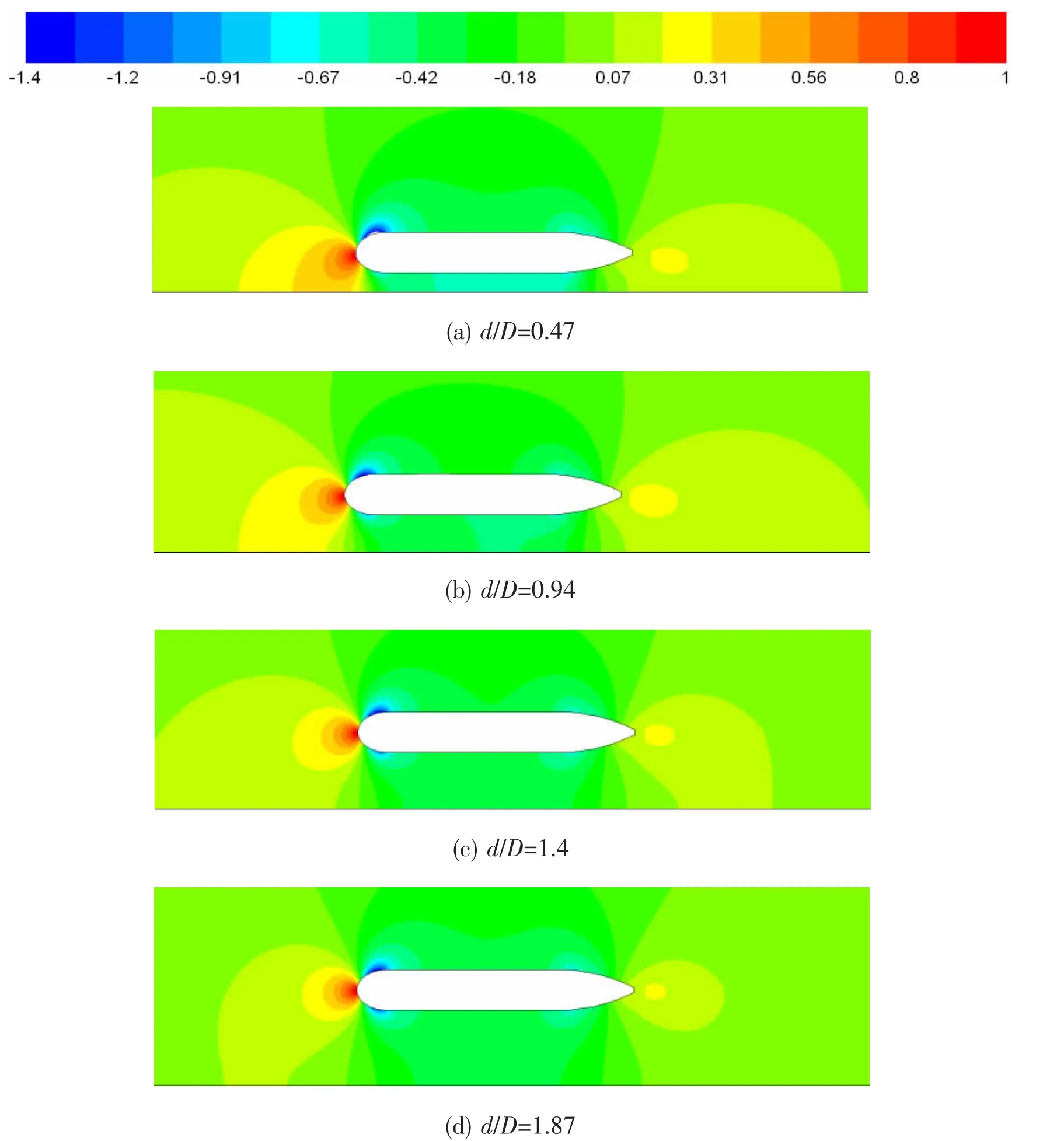
Fig.5 Pressure coefficient distribution contours of flow field between the model and the wall versus d/D
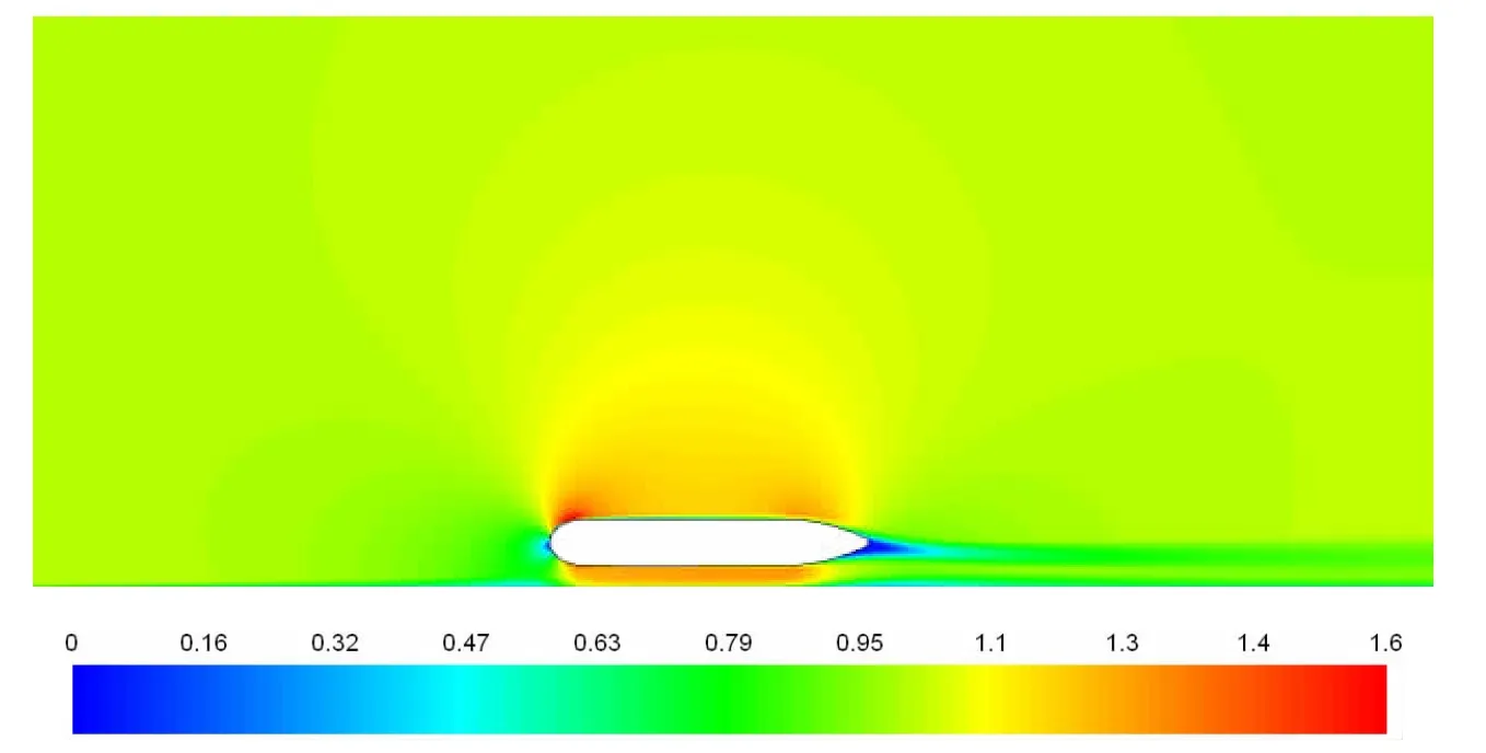
Fig.6 Velocity distribution contours of flow field between the model and the wall at d/D=0.47,U=1 m/s
Pressure coefficient distribution on the model surface at d/D=0.47,U=1 m/s is shown in Fig.7.Pressure coefficient at the bottom surface of the stem and the stern is higher than the top surface and pressure coefficient at the top surface of the central part is slightly higher than the bottom surface which causes the repulsion on the model from the wall.
The y plus distribution on model surface at d/D=1.43,U=1.5 m/s is shown in Fig.8.
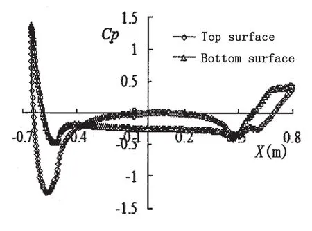
Fig.7 Pressure coefficient distribution on model surface at d/D=0.47,U=1 m/s
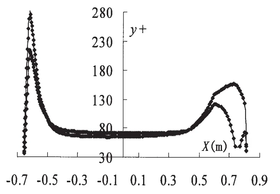
Fig.8 y plus distribution on model surface
3.2 Interaction between an axisymmetric body and a large underwater carrier
The lift,drag and pitching moment coefficients on the model at different velocities and d/D are shown in Fig.9.A typical feature in Fig.9 is that the drag increases as the flow velocity increases and the drag decreases when d/D decreases.The lift represents suction when d/D is small and declines rapidly when d/D increases gradually.The suction is 0 when d/D is 1.The lift represents repulsion when d/D changes between 1 and 2.5.When d/D is lager than 2.5,it changes suction again and keeps a small value.The pitching moment on the model is great when d/D is small.Then as d/D increases gradually,the pitching moment decreases rapidly.When d/D changes from 0.5 to 1.0,the pitching moment increases slightly and falls to the stable level finally.
The y plus distribution on model surface at d/D=0.25 and 1,U=1.5m/s is shown in Fig.10.
Pressure coefficient distribution on model surface at d/D=0.25 and 1,U=1.5 m/s is shown in Fig.11.Pressure coefficient at the stem is significantly higher than the stern which causes the drag on the model.When d/D increases,pressure coefficient at the stem increases with it.But pressure coefficient at the stern maintains stable which causes the drag greater.
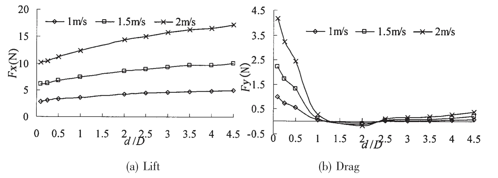
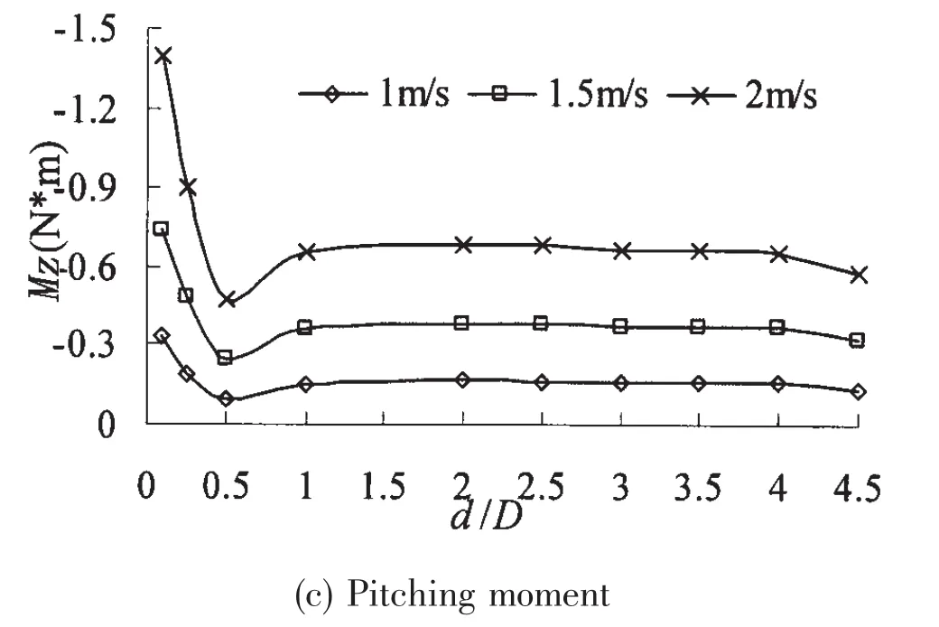
Fig.9 Lift,drag,pitching moment on the revolved model versus velocity and d/D
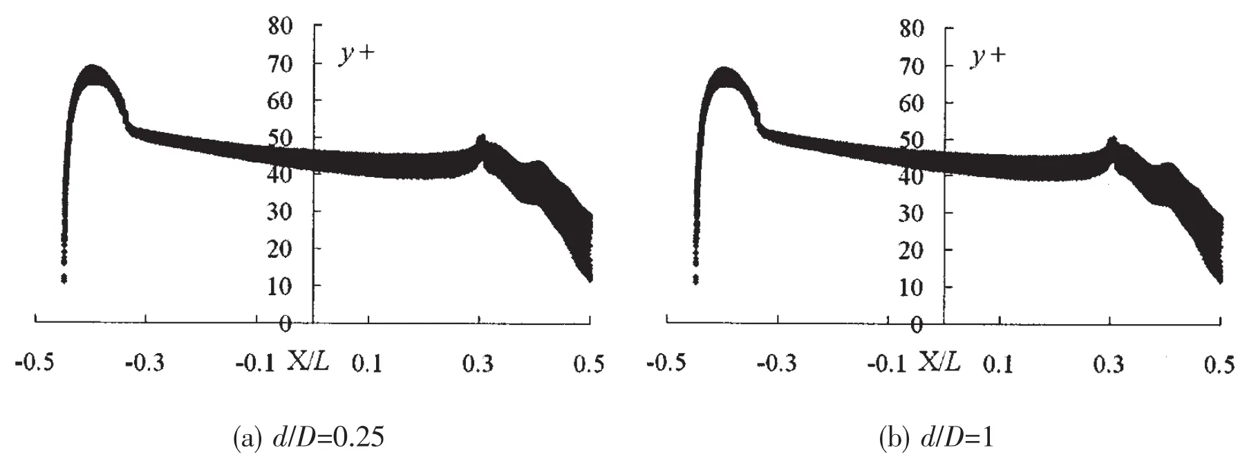
Fig.10 y plus distribution on the revolved body model surface versus d/D at U=1.5 m/s
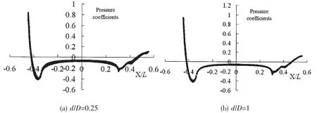
Fig.11 Pressure coefficient distribution of the revolved body model surface at U=1.5 m/s versus d/D
When the velocity is 1.5 m/s,pressure coefficient distribution contours of longitudinal section in center plane versus d/D are shown in Fig.12.A low-pressure zone is formed at the flow field between the axisymmetric body and the large underwater carrier which causes pressure coefficient at the top surface on the model higher than the bottom surface and represents suction.When d/D increases,interference on the axisymmetric body coming from large underwater carrier becomes weak,which causes decreases in suction.Meanwhile,pressure coefficient at the stem from the top to the bottom surface changes slightly,but the top surface of the stern forms a high-pressure zone which causes the pitching moment on the model.
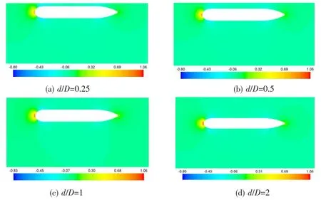
Fig.12 Pressure coefficient distribution contours of longitudinal section in center plane at U=1.5m/s versus d/D
When the velocity is 1.5 m/s,velocity distribution contours of longitudinal section in center plane versus d/D are shown in Fig.13.As shown in the figure,the turbulent boundary flow between the axisymmetric body and the large underwater carrier is easily seen and the top surface at the stern forms a low-velocity zone.When d/D increases,flow velocities around the axisymmetric body tend to be axisymmetric and wall effect is weaken.The suction and pitching moment decrease accordingly.

Fig.13 Velocity distribution contours of longitudinal section in center plane at U=1.5 m/s versus d/D
4 Conclusions
Based on the present study,the following conclusions can be drawn:
(1)The numerical method including Reynolds-Averaged Navier-Stokes Equation and the RNG k-ε turbulence model,and a special mesh strategy is usable to simulate the interaction between objects.
(2)The results obtained from the study on interaction between two-dimensional object and wall show that the repulsion from the wall exists on the model.With increase of flow velocity,the lift coefficient increases while the drag and pitching moment coefficients decrease.Furthermore,the lift,drag and pitching moment coefficients decrease as d/D increases.
(3)It is clarified from the study on interaction between an axisymmetric body and a large underwater carrier that the drag increases as the flow velocity increases and the drag decreases when d/D decreases.With the increase of d/D,suction between objects declines and gradually turns to repulsion.And finally it turns to suction and keeps a small value.Meanwhile,pitching moment on the model decreases rapidly,and then increases slightly.Finally,it falls to the stable level.
[1]Xie Nan,Gao Huanqiu.Numerical calculation of hydrodynamic interaction of two bodies floating in waves[J].Journal of Ship Mechanics,1999,3(2):7-15.
[2]Pang Yongjie,He Jingxi,Dai Jie,Ni Shaogu.The computation of hydrodynamic forces acting on underwater vehicles closing to each other[J].Ship Engineering,1997(5):8-10.
[3]Zeng Yifei,Zhu Jimao.The computation of interaction forces between underwater moving bodies[J].Ocean Engineering,1994,11(2):40-48.
[4]Li Cheng.Hydrodynamic interactions between two bodies[D].Doctor Thesis,Harbin:Harbin Engineering University,2006.
[5]Cheng Li,Zhang Liang,Wu Deming,Chen Qiang.Hydrodynamic interactions between two underwater non-lifting bodies[J].Journal of Harbin Engineering University,2005,26(1):1-6.
[6]Liang Zhang,Li Cheng,Fenglai Li,Qihu Sheng,Yu Wang.Experiment on hydrodynamic interaction between 2D oval and wall[J].Journal of Ship Mechanics,2006,10(6):1-10.
[7]Cheng Li,Zhang Liang,Wu Deming,Wang Yu.Simplified algorithm for wall effect on the lift of 2D rankine oval[J].Journal of Harbin Engineering University,2006,27(1):42-47.
[8]Cheng Li,Luo Qingjie,Zhang Liang,Wu Deming.On the forces of 3D blunt-end bodies near wall[J].Chinese Journal of Hydrodynamics,2008,23(2):149-157.
[9]Liao Guojun,Xue Jiaxing.Moving meshes by the deformation method[J].Journal of Computational and Applied Mathematics,2006,195:83-92.
[10]Guo Zheng,Li Xiaobin,Qu Zhanghua,Liu Jun.Simulation of flows past multi-body in relative motion with dynamic unstructured method[J].Acta Aerodynamica Sinica,2001,19(3):310-316.
[11]Guo Zheng,Liu Jun,Qu Zhanghua.Dynamic unstructured grid method with applications to 3D unsteady flows involving moving boundaries[J].Acta Mechanica Sinica,2003,35(2):140-146.
[12]Cavallo P A,Neerai Sinha,Feldman G M.Parallel unstructured mesh adaptation method for moving body applications[J].AIAA Journal,2005,43(9):1937-1945.
[13]Baker T J.Adaptive modification of time evolving meshes[J].Computer Methods in Applied Mechanics and Engineering,2005(194):4977-5001.
[14]Baker T J.Mesh movement and metamorphosis[J].Engineering with Computers,2002,18(3):188-198.
[15]Baker T J.Mesh deformation and modification for time dependent problems[J].International Journal for Numerical Methods in Fluids,2003,43:747-768.
[16]Baker T J,Cavallo P A.Dynamic adaptation for deforming tetrahedral meshes[R].AIAA Paper 99-3253,1999.
[17]Cavallo P A,Dash S M.Aerodynamics of multi-body separation using adaptive unstructured grids[R].AIAA Paper 2000-4407,2000.
[18]Murayama M,Nakahashi K,Matsushima K.Unstructured dynamic mesh for large movement and deformation[R].AIAA Paper 2002-0122,2002.
[19]Nathan C P,Davy M B,Shyy W.Parallel computing of overset grids for aerodynamic problems with moving objects[J].Progress in Aerospace Sciences,2000,36:117-172.
[20]Roy Koomullil,Gary Chenga,Bharat Soni,Ralph Noack,Nathan Prewitt.Moving-body simulations using overset framework with rigid body dynamics[J].Mathematics and Computers in Simulation,2008(78):618-626.
[21]Weihs D,Ringel M,Victor M.Aerodynamic interactions between adjacent slender bodies[J].AIAA Journal,2006,44(3):484-484.
[22]Alexander V F,Vitaly G S,Norman D M.Theoretical modeling of two-body interaction in supersonic flow[J].AIAA Journal,2010,48(2):258-266.
- 船舶力学的其它文章
- Transient Dynamic Analysis of Towed Low-tension Cable with Experimental Verification
- Characteristics of the Severe Slugging under Different Gas-Liquid Physical Parameters
- Washes Produced by High Speed Displacement Ships in Shallow Water:Prediction vs Measurements
- Application of the Loading Inherent Subspace Scaling Method on the Whipping Responses Test of a Surface Ship to Underwater Explosions
- Research on Multiple Excitations Inversion-oscillations
- Development of Experimental Rig for Marine Propulsion Shafting and Longitudinal Vibration Characteristic Test

