Development of Experimental Rig for Marine Propulsion Shafting and Longitudinal Vibration Characteristic Test
LU Po,ZHAO Yao,ZHANG Gan-bo,LI Liang-wei
(School of Naval Architecture&Marine Engineering,Huazhong University of Science&Technology,Wuhan 430074,China)
1 Introduction
Marine propeller-shafting system is a changer of engine torque and propeller thrust.Owing to asymmetry of stern or protrusions of control surface,the non-uniform of wake field near stern is unavoidably existent,constituting the main reason of axial oscillatory propeller thrust.Small variations in thrust axially acting on shaft resulting in the longitudinal vibration of propulsion shafting generate hull vibration through hydrodynamic stiffness of the lubricant oil film between tilting pads and thrust collar.Hence,the longitudinal vibration of propulsion shafting is a secondary essential exciting source of hull vibration and acoustic radiation at low frequency[1].In recent years,this field receives much research attentions,and a lot of practical measures are proposed,including passive[2],semi-active[3]and active techniques[4-6].In these detailed studies,the aim has been to minimize the longitudinal vibration transmission or oscillatory thrust into hull,and one option is to decrease the hydrodynamic stiffness at blade passing frequency.
So far,control prototype devices presented in literatures on longitudinal vibration attenuation of propulsion shafting include resonance changer[2],semi-active tuned pneumatic vibration absorber[3],active magnetic thrust bearing[4],pneumatic servo-controller[5],electromagnetic mass damping[6],and so on.To verify accuracy of theoretical analysis and effectiveness of these control devices,various experimental rigs for propulsion shafting had been designed,which were taken as benchmark to simulate full scaled marine propeller-shafting system.By comparing experimental results with and without these devices,usually in two aspects of frequency domain and time domain,the success of control strategies can be judged.Thus the development of experimental shaft rig is also concerned.
A laboratory scaled experimental rig for propulsion shafting is described in this paper.As preliminary experimental investigation,the longitudinal vibration characteristics of shaft,the derivation of non-dimensional frequency equation and the estimation of longitudinal stiffness of thrust bearing are included.Since the nonlinear factors of shaft are neglected,there are a few errors between experimental results and theoretical analysis.
2 Comparison of typical experimental shaft rigs
Generally,marine propulsion shafting is constituted of engine,transfer shafts,coupling,propeller,journal bearings,thrust bearing and other auxiliary units[7].But for laboratory scaled experimental rig,it is not necessary to combine all of those parts.In fact,there are some structural differences between experimental rigs developed by researchers owing to themselves study points.
Two typical laboratory scaled rigs are outlined in Fig.1.They are able to represent propeller-shafting units in marine arrangement,although one is simple and the other is relatively complex,which commonly consists of propeller,propeller shaft,thrust bearing,flexible coupling and electromotor.These standard components are easy to be purchased and assembled.To produce propeller-induced vibration,additional water tank is required to provide water operating condition.Constrained by laboratory space,the volume of tank is limited or even very small as a result that it is likely to induce two associated problems,which usually occur at high rotating shaft speed,propeller load instability and rotating speed fluctuation.However,if the power of engine is low or the propeller diameter is small,these problems may not be outstanding.Some measures are capable of alleviating these negative influences,such as mounting flow-leading device and circulating pipe[10],but the complicacy of experimental rig will be increased and the reliability will be decreased.

Fig.1 Typical laboratory scaled rigs
An effective alternative is to utilize mechanical actuator to replace propeller as axial vibration exciting source,for example hydraulic actuator[3]and pneumatic actuator[4],shown in Fig.2.The propeller thrusts are able to decomposed into steady state thrust and oscillatory thrust,in which the former is driving force of sailing and the latter is longitudinal vibration excitation of propulsion shafting.Thus the steady state thrust can be applied by means of a mechanic actuator connected to power supply,while a shaker provides the oscillating components of thrust simulating blade rate vibration.Obviously,the combined devices will not give rise to above mentioned problems induced by propeller rotating in limited water tank.

Fig.2 Thrust driver[4]
Another apparent difference is the frame form of thrust bearing.Due to superior lubrication and thrust transmission performances,the Michell thrust bearing is adopted in marine extensively,which consists of shaft collar,tilting pads and corresponding block.The tilting design allows the establishment of hydrodynamic lubrication between the collar and pads.Taking cost into account,it is not necessary to develop such thrust bearing in laboratory as outlined in literatures by the majority of researchers.Generally,the form of thrust bearing is dependent on the function of experimental rig.If the shaft was driven by a motor,the lubricant thrust bearing is essential,meaning that the employed device functioning as thrust transmission was relatively similar to thrust bearing in marine.Whereas,a thick steel plate even can be used to substitute for thrust bearing[3-4].As a vibration signal generator,several testing devices constituting an intergraded testing system are required to measure shaft longitudinal vibration information,including shaft rotating speed,axial response and axial thrust.To satisfy these tests,some specific components are added in experimental rig.For example,a strain gauge load cell is sandwiched between the thrust bearing and the block for testing axial force transmitted into block,a circular shoulder is fixed to shaft where its axial motion can be measured by a vibrometer,and so on.
By comparing experimental rigs of propeller-shafting mentioned in references,two points are synthesized as follows:
(1)Provided that a motor is not a component in experimental rig arrangement,the shaft can be simplified as a tie-rod structure.The form of thrust bearing also can be built as simple as possible and the propeller thrust can be substituted for combination of a mechanic actuator and a shaker providing steady state thrust and oscillatory thrust,respectively.The most attractive advantage of this type rig is its simplicity and economy,but it is not beneficial to overall assess effectiveness of control devices equipped afterward,especially the rotating operation condition;
(2)The shaft is capable of rotating in any speed driven by a motor.Correspondingly,the form of thrust bearing is relatively complex,which requires lubricant and other auxiliary system.Referring to the embodiment of propeller thrust,one option is propeller with matched water tank and the other is the above mentioned force assembly.
3 Laboratory scaled model development
The development of laboratory scaled experimental rig for propulsion shafting follows the same design procedures of marine propulsion shafting,which consists of demand analysis,arrangement design,alignment and vibration calculation[7].To embody propeller thrust and satisfy subsequent equipment of control device,general design of the experimental shaft rig is described as follows:
(1)The experimental rig covers the majority of components included in marine propulsion shafting,such as electromotor,thrust bearing and auxiliary lubricant system.The shaft is capable of rotating in any speed clockwise and counter-clockwise;
(2)The axial exciting thrust is induced by combination of static and dynamic force devices rather than propeller with water tank;
(3)There is one longitudinal resonance frequency within the range of 5~100Hz at least;
(4)The foundation supporting main components is independent in order to minimize structural-borne sound excitation from motor and other apt vibration generator.
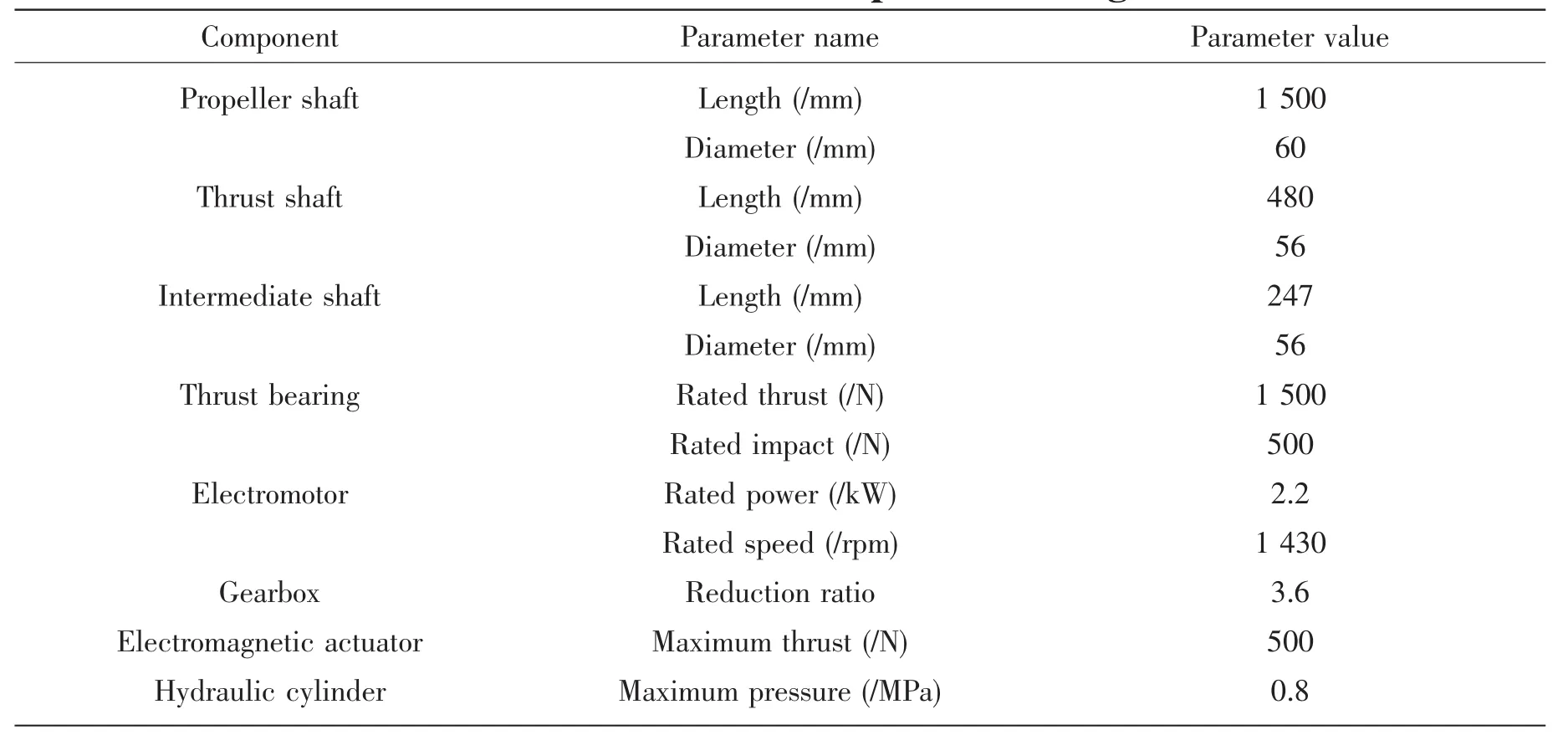
The general arrangement of experimental rig is depicted in Fig.3.The rig consists of exciting force generator unit,driver unit,shaft unit and support unit,in which the exciting force generator unit is established by combination of hydraulic steady loading system and dynamic loading system.Steady state thrust is applied by a hydraulic cylinder connected to an oil pump and an electromagnetic actuator is mounted behind it to produce oscillatory thrust controlled by a signal generator and a power amplifier.Since the shaft has to rotate,a difficult encountered is how the steady thrust and oscillatory thrust can be smoothly combined to act on the rotating shaft,inducing the rotating shaft occurs longitudinal vibration.The problem is overcome by sandwiching a load device between the hydraulic cylinder and the shaft.By separating the rotating shaft and force generator,the combined thrusts are forced at the end of shaft by an inner circular shoulder via two thrust roller bearings mounted in chamber of the load device.
The whole components of experimental rig fixed on supporting foundation are sequenced as follows:force signal generator→power amplifier→electromagnetic actuator→hydraulic cylinder→load device→propeller shaft→journal bearing→clamp coupling→thrust shaft→thrust bearing→elastic coupling→intermediate shaft→gearbox→electromotor.To satisfy alignment demand,the location of journal bearing is movable axially.The design process of thrust bearing is complicated comprising thrust pad type and number,minimum thickness of oil film and lubricant oil flow,and so on.Referring to the experimental rig,the tapered flat thrust bearing is selected to meet installation of control device.An elastic coupling is incorporated between the thrust shaft and the intermediate shaft to isolate vibration from gearbox and to compensate alignment.Moreover,the coupling is convenient to be separated into two parts for subsequent experimental investigation.The entire experimental rig is designed according to related standards strictly and a list of parameters is contained in Tab.1.

Fig.3 General arrangement of experimental rig

Tab.1 Parameters of experimental rig
In addition,auxiliary hydraulic,lubricant and operating systems are required to maintain normal operation of the experimental rig.It is easy to see that the load unit and the lubricant unit are all driven by hydraulic system,thus the independence of both units is essential to avoid mutual disturbances,which can easily be realized by utilizing independent pipes.Besides,all operations of the experimental rig are integrated in one panel in order to be more conveniently operated.Fig.4 shows a photograph of the built experimental rig.Since the shaft has to be isolated from external vibration,the entire shaft assembly is supported by independent steel foundation and mounted on a reinforced concrete block damped by groove filled with sand.Via series of running-in tests and equipment debugging,the experimental rig works steadily without any abnormal noise,oil leakage and heat,and can be used to conduct characteristic test.

Fig.4 A photograph of experimental rig
The merits of the experimental rig are summarized as follows:
(1)The propeller thrust is satisfyingly simulated by combination of hydraulic cylinder and electromagnetic actuator,on one hand,there are not negative influences such as load instability and rotating speed fluctuation induced by propeller rotating in limited water tank,and on the other hand,the magnitudes of static and dynamic thrusts can be modified continuously to comprise various testing combinations;
(2)The electromagnetic actuator is not only an oscillatory thrust generator representing variations in propeller thrust,but also an exciting device for testing,implementing integration of load system and test system;
(3)The hydraulic load unit and hydraulic lubrication unit are independent,and all operations are integrated in one panel to enhance practical reliability and operability.
4 Experimental investigation
4.1 Modal test
The structural non-parametric model generally expressed by frequency response function can be obtained by experimental modal analysis,from which dynamic characteristics such as natural frequency,damping ratio and mode shape are determined by using appropriate parameter identification method[13].One reason to explain the complicacy of longitudinal vibration analysis for marine propulsion shafting is that it is difficult to ascertain longitudinal stiffness and participating mass of thrust bearing.As is known,the longitudinal stiffness of thrust bearing is an equivalent value of components consisting of thrust collar,oil film,thrust pads,buttons and foundation.Unfortunately,there are nonlinear factors like clearance and contact in thrust bearing[14],resulting in theoretic difficulty of longitudinal stiffness to thrust bearing and then longitudinal vibration analysis for propulsion shafting.In fact,experimental investigation is the only way to determine longitudinal stiffness of thrust bearing accurately.Besides,another aim of experimental investigation to shaft is to test its longitudinal characteristics,which in turn verifies correctness of theoretic approach.
The modal test of shaft is undertaken at its irrotional state and the elastic coupling is separated in advance.In view of the fixed location of actuator,it is convenient to adopt single input and multi output testing approach.Since the longitudinal modes are only concerned,the piezoelectric accelerometers are all fitted along axial orientation on propeller shaft and thrust shaft.Fig.5 shows the schematic diagram of accelerometer assembly,in which the measuring points 5#and 6#are located at clamp coupling and elastic coupling,respectively.

Fig.5 Schematic diagram of accelerometer assembly

Fig.6 Inertance function at different measuring point
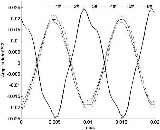
The excitation source is configured so that it imposes a certain magnitude of thrust to shaft in axial direction,resulting in its longitudinal vibration.For the purpose of experiment,it is assumed that the frequency range of interest is between 5 and 100 Hz.By dealing with test data,the inertance function corresponding to different measuring point is depicted by waterfall plot as Fig.6.It is observed from Fig.6 that the inertance function of measuring points 1#through 5#agrees well with each other in comparison with measuring point 6#,which shows the consistence of longitudinal vibration characteristics of shaft.At low frequency excitation,the propeller shaft,clamp coupling,thrust shaft and thrust bearing vibrate axially as an entirety.However,due to existence of lubricant oil inside of thrust bearing,there is phase delay between measuring points 1#through 5#located at propeller shaft and measuring point 6#at thrust shaft.It can be seen from measured waveform given in Fig.7.
The marine propulsion shafting endures large additional water pressure when immersed in water,that is,the propulsion shafting is subject to axial prestress.It is easy to simulate this prestress by exerting static hydraulic pressure at the end of shaft in experimental rig.Taking measuring point 2#for example,the measured inertance function corresponding to different hydraulic thrust is shown in the waterfall plot in Fig.8.Unexpectedly,the influence of axial prestress on natural frequency is not demonstrated,and one explanation is that the imposed static thrust limited by capacity of hydraulic cylinder is not large enough.In principle,once the prestress is increased to a certain value,its influence should not be neglected.

Fig.7 Measured waveform at different measuring point

Fig.8 Measured inertance function of measuring point 2#via different hydraulic thrust
4.2 Theoretical analysis
The experimental modal analysis provides an effective approach to estimate longitudinal stiffness of thrust bearing.Generally,shaft speed corresponding to one order blade passing frequency occurs near the full power operating speed of shaft,so the first longitudinal mode frequency is quite concerned.Previously,the first longitudinal mode frequency is obtained by experimental modal analysis,the longitudinal stiffness of thrust bearing can be determined usually based on single degree of freedom model.Obviously,this method is simple and comprehensive,but it is effective only if the longitudinal stiffness of thrust bearing is far greater than shaft.Since the length of experimental shaft is a bit short,enabling that its longitudinal stiffness is likely to be equal to thrust bearing.Hence,it is not suitable to utilize above-mentioned approach to estimate longitudinal stiffness of thrust bearing,and a new approach is required.
To comprehend general rule of longitudinal stiffness of thrust bearing to longitudinal vibration characteristics,it is beneficial to build non-dimensional mathematic model.Thus the experimental shaft is simplified as continuous elastic model as left-hand is lumped,right-hand is lumped and elastic fixed,the middle is uniform shaft,shown in Fig.9.

Fig.9 Continuous model of experimental shaft
The analytical solution to longitudinal vibration equation of unifrom shaft is given by:

where k is wave number of longitudinal vibration.
Boundary conditions are expressed as:

where M,m and K are mass of load device,mass and longitudinal stiffness of thrust,respectively.S and l are cross section area and effective length of shaft.
Substituting equation(1)into equation(2),then the following equation is obtained:

Provided that equation(3)has nonzero solutions,thus frequency equation can be written as:

where ρ is density of shaft material.
By introducing the following non-dimensional quantities:

Substituting above non-dimensional quantities into Eq.(4),the non-dimensional frequency equation is given as follows:

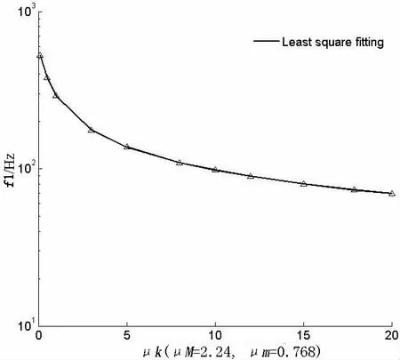
The Eq.(6)shows that longitudinal vibration frequency is determined by μm,μMand μK.Referring to experimental shaft,μmand μMis known,then the relationship between μKand first longitudinal mode frequency f1can be plotted in Fig.10,in which the solid line represents fitted equation with least square fitting approach.By substituting the tested first longitudinal mode frequency 78.4 Hz into the fitted equation,the longitudinal stiffness of thrust bearing is 3.065×10⁷N/m.It is worth to note that the obtained value is a preliminary static stiffness of shaft at irrotional state.In fact,the longitudinal stiffness of thrust bearing is always variational corresponding to different rotating speed of shaft due to the variation of hydrodynamic stiffness and damping of lubricant oil film[8].
Fig.11 shows the comparison of measured inertance function with calculated values obtained by transfer matrix method from mathematical model,which contained the estimated longitudinal stiffness of thrust bearing.As expected,there is a certain error between experimental results and theory.A straightforward explanation is that the nonlinear factors of shaft are neglected in mathematical model.

Fig.10 Relationship between μKand first longitudinal vibration frequency f1

Fig.11 Comparison of measured inertance function with theory
5 Conclusions
Work described in this paper is the development of laboratory scaled experimental rig for propulsion shafting and its longitudinal vibration characteristic test.The differences of experimental shaft rig depicted in literatures are detailed summarized,especially the simulation of propeller thrust and thrust bearing.Since the propeller with limited water tank is likely to induce load instability and rotating speed fluctuation,while an alternative is the combination of mechanical actuator and shaker.It is clear that the second method is more advantageous and adopted by this paper.
The measured inertance function allows the experimental determination of longitudinal modes of shaft,especially the first longitudinal mode frequency.The experimental results illustrate that the propeller shaft,clamp coupling,thrust shaft and thrust bearing vibrate axially as an entirety at low frequency excitation.Due to existence of lubricant oil inside of thrust bearing,there is phase delay between measuring points located at propeller shaft and measuring point at thrust shaft.Besides,the prestress has an effect on longitudinal modes of shaft,but it is not demonstrated in the experimental investigation limited by capacity of experimental rig.
Based on continuous model,the non-dimensional frequency equation is derived,showing that the longitudinal modal frequency is related to mass ratio and longitudinal stiffness ratio.By substituting the first frequency test value,the longitudinal stiffness of thrust bearing is obtained as the input of theoretic analysis for longitudinal vibration of shaft.There is a certain error between the experimental results and theory,and one explanation is that a few nonlinear factors are existent in experimental rig.
[1]Zhao Y,Zhang G B,Li L W.Review of advances on longitudinal vibration of ship propulsion shafting and its control technology[J].Shipbuilding of China,2011,52(198):259-269.
[2]Goodwin A J H.The design of a resonance changer to overcome excessive axial vibration of propeller shafting[J].Institute of Marine Engineers Transactions,1960,72:37-63.
[3]Brennan M J,Day M J,Randall R J.An experimental investigation into the semi-active and active control of longitudinal vibrations in a large tie-rod structure[J].Journal of Vibration and Acoustics,1998,120(1):1-12.
[4]Lewis D W,Allaire P E,Thomas P W.Active magnetic control of oscillatory axial shaft vibrations in ship shaft transmission systems,part 1:System natural frequencies and laboratory scaled model[J].Tribology Transactions,1989,32(2):170-178.
[5]Baz A,Gilheany J,Steimel P.Active vibration control of propeller shafts[J].Journal of Sound and Vibration,1990,136(3):361-372.
[6]Johnson B G,Hockney R,Eisenhaure D,et al.System and method for damping narrow band axial vibrations of a rotating device[P].U.S.Patent,1994,No.5291975.
[7]Yao S G,Xiao M.Marine power plant[M].Beijing:National Defense Industry Press,2006.
[8]Pan J,Farag N,Lin T,et al.Propeller induced structural vibration through the thrust bearing[C]//Acoustics 2002-Innovation in Acoustics and Vibration.Adelaide,Australia,2002.
[9]Wang J S,Liu Y Z.Test and analysis of axial vibration hypostatic test rig of the ship’s propeller shafting[C]//Proceedings of Conference on Mechano-electronics.Taiyuan,China,2009.
[10]Zhang T Y,Wang C P,Xu B Q,et al.Development of the test bed for marine diesel shaft and its components[J].Chinese Internal Combustion Engine Engineering,1985(2):10-16.
[11]Li L W,Zhao Y,Zhang G B.Research of axial coupling vibration characteristic of marine shaft test bed[C]//Proceedings of Conference on Ocean Steel.Luoyang,China,2010.
[12]Zhao Y,Li L W,Li T Y,et al.Longitudinal vibration test bed of ship propulsion shafting[P].China Patent,2011,No.CN102297753A.
[13]Zhang L M.Vibration test and dynamic analysis[M].Beijing:Aviation Industry Press,1992.
[14]Xu Y X,Zhong X T,He X X.Longitudinal vibration of ship shafting[M].Beijing:China Communication Press,1985.
- 船舶力学的其它文章
- Transient Dynamic Analysis of Towed Low-tension Cable with Experimental Verification
- Characteristics of the Severe Slugging under Different Gas-Liquid Physical Parameters
- Research on Interaction between a Large Underwater Carrier and a Mini-underwater Vehicle
- Washes Produced by High Speed Displacement Ships in Shallow Water:Prediction vs Measurements
- Application of the Loading Inherent Subspace Scaling Method on the Whipping Responses Test of a Surface Ship to Underwater Explosions
- Research on Multiple Excitations Inversion-oscillations

