基于含锌有机配位聚合物的微孔碳的合成及其电化学性能
钱佳晟 刘明贤 甘礼华 吕耀康 陈玲艳 叶瑞杰 陈龙武
(同济大学化学系,上海200092)
1 Introduction
Supercapacitors,also known as electrochemical supercapacitors or ultracapacitors,which combine the advantages of dielectric capacitor and rechargeable battery,have received great attention in the past several decades for their promising applications in hybrid vehicles,energy storage,telecommunication systems and so forth.1-4As the key section of supercapacitors,the electrode materials play a leading part in the electrochemical performances.5,6With the features of high specific surface areas,large pore volumes,low cost,commercial availability,as well as stable physical and chemical properties,microporous carbons have been one of the ideal candidates as electrode materials for the fabrication of supercapacitors.For instance,Zhao and co-workers7used sucrose as the precursor to prepare microporous carbons which exhibit a specific capacitance of 232 F·g-1at a current density of 0.1 A·g-1.Kyotani et al.8used zeolite as a hard template to fabricate microporous carbons via impregnation-chemical vapor deposition method,showing an electrochemical capacitance of 215 F·g-1at 0.25 A·g-1.However,common microporous carbons including activated carbons suffer from the disadvantages of irregular island charge and extremely small micropores,which leads to limited transportation and poor accessibility of electrolyte ions into the pore surface of carbons.9This drawback causes much difficulty to achieve proportionality between their specific capacitances and surface areas,especially in case of a relatively high current density.
In recent years,a new family of porous materials named metal organic coordination polymers(MOCPs)has attracted much attention for its promising applications in catalysis,gas storage and separation,environmental science,etc.10-12Since Robson13first proposed the concept of coordination polymer in 2000,it has been rapid developed over the past decade because coordination polymer has a variety of space topology and the unique optical,electrical,and magnetic characteristics.Xu et al.14,15reported for the first time a new pathway for synthesizing porous carbons by using Zn4O(C2O4)3·(DMF)8(C6H5Cl)(MOF-5,DMF:N,N-dimethylformamide)as the template and furfuryl alcohol as the precursor.MOF-5 was degassed under vacuum at 200°C,and then the precursor gas was introduced into the open channels of MOF-5,followed by polymerization and carbonization to produce porous carbons.The regular and open networks of MOCPs provide a platform for the synthesis of microporous carbon materials with relatively regular micropores.This could benefit the fast transportation and diffusion of aqueous electrolyte ions(e.g.,KOH solution)which have relatively small sizes.However,the existence of inaccessible micropores inside the framework of MOCPs impedes the effective entrance and well dispersity of carbon sources,resulting in a challenge to control the microstructure of produced carbon materials.16
Herein,we report a novel and facile approach to prepare microporous carbon based on zinc-organic coordination polymer.Tartaric acid could form coordination bonds with zinc ions to obtain zinc-tartaric acid coordination compound.Besides,there is hydrogen-bonding interaction between tartaric acid and resorcinol/formaldehyde(R/F)resol,which benefits homogeneous dispersity of Zn-containing coordination compound into the networks of R/F prepolymer,leading to the final formation of microporous carbons with relatively regular and large micropores.In addition,the relationship between experimental parameters and electrochemical performance of the microporous carbons was investigated.This study shows potential for such microporous carbons as electrodes for extensive supercapacitor applications.
2 Experimental
2.1 Materials
Resorcinol(99.5%),formaldehyde solution(37%(w)),Na2CO3(99.5%),HCl(37%(w)),tartaric acid(99.5%),and ZnCl2(99.5%)were analytical reagents and were purchased from Sinopharm Chemical Reagent Co.and used without any purification.Polytetrafluoroethylene(PTFE)binder was purchased from Shanghai 3F New Materials Co.,Ltd.Nickel foams were purchased from Shanghai Hongxiang Screen Factory.
2.2 Preparation of microporous carbons
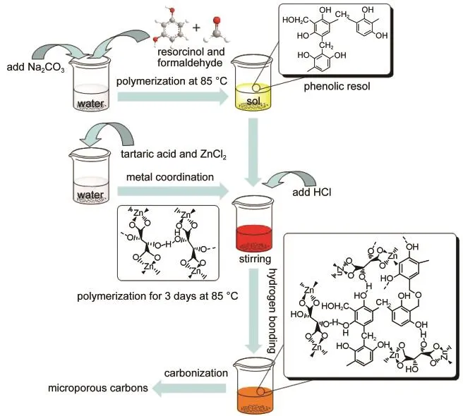
0.792 g(7.2 mmol)resorcinol,10 mL Na2CO3(9.6 mmol·L-1)and 4 mL(54 mmol)formaldehyde solution were mixed in 60 mL distilled water.The mixture was heated to 85°C for 45 min to obtain R/F resol and then cooled down to room temperature.Certain amount of tartaric acid(the molar ratio of resorcinol to tartaric acid is 3:2,1:1,and 2:3),ZnCl2(the molar ratio of ZnCl2to tartaric acid is 1:1),6 mL HCl and 20 mL distilled water were mixed with stirring to obtain Zn-tartaric acid coordination compound.Afterwards,the Zn-tartaric acid coordination compound was added into the R/F resol under stirring.A reddish homogeneous emulsion was formed by another stirring for extra 30 min.This emulsion was kept in an oven at 85°C for 3 days to obtain R/F and zinc-organic coordination copolymer.Methanol was added for next 3 days and refreshed everyday to exchange the distilled water inside.The copolymer sample was dried under ambient pressure at 100°C.For carboniza-tion,the sample was first heated to 550°C under N2atmosphere and kept for 30 min,and then heated to 950°C for 8 h at a heating rate of 5 °C·min-1.Finally,microporous carbons were obtained and denoted as MIC-1,MIC-2,and MIC-3 corresponding to the samples prepared by a molar ratio of resorcinol/tartaric acid of 3:2,1:1,and 2:3.The schematic synthesis procedure is shown in Scheme 1.
2.3 Measurements
Powder X-ray diffraction(XRD)was carried out by an X-ray diffractometer(Bruker AXS,D8 Advance)with monochromatic Cu Kαradiation(λ=0.15418 nm).The 2θ angular regions between 10°and 70°were recorded.The nitrogen sorption isotherms were measured at-196°C by using Mircomeritics,Tristar 3000.The Brunauer-Emmett-Teller(BET)method was utilized to calculate the specific surface areas(SBET)using adsorption data in a relative pressure(p/p0)ranged from 0.005 to 0.2.The pore volumes and pore size distributions were derived from the adsorption branches of isotherms using the Barrett-Joyner-Halenda(BJH)model,and the total pore volumes(Vtotal)were estimated from the adsorbed amount at a relative pressure of 0.993-0.998.
All electrochemical measurements were carried out in a two-electrode cell(capacitor)with 6.0 mol·L-1KOH aqueous solution as electrolyte at ambient temperature.For the preparation of one electrode,90%(w)active materials were mixed with 10%(w)polytetrafluoroethylene binder(PTFE 60%(w)dispersion in ethanol)to form slurry.The slurry was spread onto a nickel-foam(1 cm2),followed by pressure under 25 MPa and drying at 100°C to prepare electrode.After that,two electrodes with same mass of materials were put together,and a polypropylene(PP)membrane was sandwiched between them as a separator.Two identical electrodes were adopted as cathode and anode for the cell configuration.
Before the measurements,the capacitor cell was pumped for 30 min so that the active material was soaked fully by the electrolyte.Cyclic voltammograms(CVs),galvanostatic chargedischarge(GCD),and electrochemical impedance spectroscopy(EIS)were all carried out on CHI 660D Workstation(CH Instrument,Inc.).
The specific capacitance(C)is calculated according to the following equation(1):

where ΔQ is the charge integrated from the whole voltage range,ΔV is the whole range of voltage window,and m is the total mass of carbon on the two electrodes,v is the scan rate of CV measurements.
Galvanostatic charge-discharge measurements at various current densities were performed with a voltage range of 0 to 1 V.Specific capacitance of each electrode was calculated according to the following equation(2):

where I is the discharge current,Δt is the discharge time from 0 to 1 V,ΔV is the voltage difference within the discharge time Δt.
Electrochemicalimpedance spectroscopy measurements were performed with a frequency range between 100 kHz and 10 mHz(AC perturbation amplitude is set as 5 mV)at an equi-librium open circuit potential.

Scheme 1 Schematic illustration of the preparation procedure for microporous carbons
3 Results and discussion
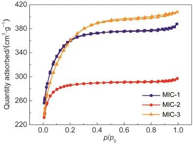
N2adsorption-desorption isotherms and pore size distributions of microporous carbons are shown in Fig.1.These curves belong to Type I isotherms with unapparent hysteresis loops,demonstrating the existence of micropores.Table 1 shows the physicochemical properties of the microporous carbons.The specific surface areas of MIC-1,MIC-2,and MIC-3 are 1231,954,and 1260 m2·g-1,in which the microporous areas are 1220,948,and 1241 m2·g-1,respectively,revealing that the as-prepared samples are all microporous carbons.The maximum total pore volume of 0.63 cm3·g-1is measured from MIC-3,implying a sufficient space for ion-transportation and high ion-capacity.The average pore sizes of the microporous carbons are 1.89-1.99 nm,as shown in Table 1.Therefore,the resultant microporous carbons possess relatively regular and large micropores.
Tartaric acid molecule has two hydroxyl groups which could form coordination bonds with a single zinc ion to obtain zinc-tartaric acid coordination compound.Besides,tartaric acid also could form hydrogen bonds with R/F resol,which facilitates the effective introduction and homogeneous dispersity of Zn-containing coordination compound into the networks of R/F prepolymer.The mixture was polymerized to produce the R/F and zinc-tartaric acid coordination copolymer.After carbonization,porous carbons with relatively regular and large micropores were prepared.Besides,the evaporation of Zn species at 950°C leads to more fruitful micropores for the carbons.The resultant microporous carbons have a specific surface area up to 1260 m2·g-1and total pore volume of 0.63 cm3·g-1.Compared with common activated carbons,the existence of such big and regular micropores in microporous carbons could play a role as the highways leading to the fast-ion migration.The unique porous structure of the microporous carbons would endow them very good electrochemical performances,as we will discuss later.

Fig.1 N2adsorption-desorption isotherms of MIC-1,MIC-2,and MIC-3

Table 1 Physicochemical properties of the microporous carbons
XRD patterns of MIC-3 are shown in Fig.2.The diffraction peaks of MIC-3 carbonized at 530°C correspond to those of ZnO(JCPDS 36-1451).This indicates that Zn-tartaric acid coordination polymer was decomposed and the resultant ZnO occupied inside the network of microporous carbons.When carbonized at 950°C,the sample shows that only two diffraction peaks at~23°and ~44°belong to the lattice planes of(002)and(100),indicating the removal of Zn species and high purity microporous carbons were obtained.Besides,the lattice plane of(002)is in series with a pure graphitic lattice and the weak intensity of(100)lattice plane involves in disordered stacking of graphites,which both demonstrate that the amorphous carbon was obtained.17

Fig.2 XRD patterns of MIC-3 after carbonization at 530 and 950°C

Fig.3 Nyquist plots of MIC-1,MIC-2,and MIC-3 measured from 100 kHz to 10 mHz
Nyquist plots of microporous carbons are displayed in Fig.3.The absence of the semicircle at high frequency implies a very good ionic conductivity at the electrode-electrolyte interface.18-20In Fig.3,no obvious semicircle appears in the curves of MIC-2 and MIC-3,indicating a good ionic conductivity.As a transition,a straight line at an angle of 45°represents the Warburg finite-length diffusion stage when electrolytic ions dif-fuse within the electrode.21All samples show short lines as seen in Fig.3,revealing an unobstructed way for electrolytic ions to reach the microporous carbonsʹsurface.In the imaginary part of the impedance at lower frequency,a sharp increase happens to follow the 45°angle line in the plots of all samples,which corresponds to a good capacitive behavior.Besides,the first intersection point on the real axis at high frequency provides the value of the electrolyte resistance,the intrinsic resistance of the active electrode material,and the contact resistance at the interface of active material current collector,defined as equivalent series resistance(ESR).18,22Owing to the same condition of electrolyte and effective adhesion between nickel foam and microporous carbons,the value of ESR should be associated with the intrinsic resistance of microporous carbons.The ESR values are measured as 0.65,0.49,and 0.46 Ω for MIC-1,MIC-2,and MIC-3,respectively.
Fig.4 shows CV curves of the microporous carbon electrodes at a scan rate of 100 mV·s-1,which all exhibit very good rectangular-like shapes without any redox peaks at potential window ranging from 0 to 1.0 V.Such good rectangular shapes are associated with an ideal electrochemical behavior based on double layer ionic adsorption and exchange,which also implies that microporous carbon electrode has a quick charge and discharge feature.23,24Apparently,MIC-3 has the largest rectangular area among the three samples,which stands for a much higher specific capacitance(149 F·g-1)than those of MIC-1(99 F·g-1)and MIC-2(97 F·g-1).
Fig.5 shows CV curves of MIC-3 electrode under various scan rates in 6 mol·L-1KOH solution.A rectangular-like shape of MIC-3 was found between 0 and 1 V at 100 mV·s-1,which is much better than most other microporous carbons,7,8,25demonstrating splendid pourable ion-transportation inside the pores and tunnels with a rapid charging-discharging characteristic owing to its regular porous structure.As the scan rate increases,CV curves for MIC-3 electrode become tilted but still maintain some rectangular-like shape even at 1000 mV·s-1.With an increasing scan rate of 100,500,and 1000 mV·s-1,specific capacitances of the MIC-3 electrode are calculated as 149,86,and 62 F·g-1,respectively.These values are almost double higher than those of microporous carbon prepared by using zeolite as the template and chitosan-based microporous carbons at the same scan rate.26,27This could be contributed by relatively regular and large micropores for a more convenient free-migration of solvated electrolytic ions.

Fig.4 CV curves of microporous carbon electrodes at a scan rate of 100 mV·s-1in 6 mol·L-1KOH solution

Fig.5 CV curves of MIC-3 electrode under different scan rates in 6 mol·L-1KOH solution
For the further study for electrocapacitive performances of microporous carbons,GCD measurements are tested for charging-discharging capacities behaviors.28Fig.6 exhibits GCD curves of microporous carbon electrodes at a current density of 1 A·g-1.The discharging curves of microporous carbons are symmetric with the corresponding charging curves,which represents linear-like relationships between time and potential.Only a tiny IR drops were in the GCD curves,indicating a small Ohmic resistance existed and good capacitive performance.22Meanwhile,the charge-discharge time of MIC-3 is somewhat longer than other samples,which represents a larger specific capacitance.As expected,the capacitance value of 196 F·g-1for MIC-3 is higher than those of MIC-1(146 F·g-1)and MIC-2(127 F·g-1)because of higher specific surface area and larger micropores,as shown in Table 1.

Fig.6 GCD curves of microporous carbon electrodes at a current density of 1A·g-1in 6 mol·L-1KOH solution

Fig.7 GCD curves of MIC-3 electrode under different current densities in 6 mol·L-1KOH solution

Fig.8 Long-term cycle stability of MIC-3 electrode in 6 mol·L-1 KOH solution at 1A·g-1
As sample MIC-3 exhibits the highest specific capacitance in Fig.6,deeply measurement for high-rate charging-discharging of MIC-3 electrode is shown in Fig.7.The specific capacitances are 196,157,and 137 F·g-1at current densities of 1,5,and 10 A·g-1,respectively.The specific capacitance of MIC-3 electrode at 1 A·g-1is even higher than those of MOF-templated hierarchical porous carbons and peasecod-based activated carbons.14,15,29At a higher current density of 20 A·g-1,the specific capacitance of MIC-3 electrode still remains 109 F·g-1owing to the regular porous structure for rebuilding the electric double layers.On the other hand,a specific capacitance of 205 F·g-1is measured at a current density of 500 mA·g-1,which is much higher than that of activated carbon fiber,30and is on the same level as that of N-doped activated CNT.26Fig.8 shows the long-term cycle stability of MIC-3 electrode.The electrochemical capacitance of MIC-3 electrode decreases from 201 to 197 F·g-1with a retention of 98%,indicating a good long-term stability of the microporous carbons.
4 Conclusions
In summary,microporous carbon was successful prepared based on zinc-organic coordination polymer.Through the coordination interaction of zinc ions and tartaric acid,zinc-tartaric acid coordination compound was prepared and then it was introduced into the open networks of R/F resol by utilizing the H-bonding interaction to fabricate microporous carbons with relatively regular and large micropores.A typical microporous carbon(MIC-3)has a high specific surface area of 1260 m2·g-1and a large pore volume of 0.63 cm3·g-1.MIC-3 as electrode shows an ESR value of 0.46 Ω,ideal capacitive behavior of rectangular shape,high specific capacitance of 196 F·g-1at 1 A·g-1and high retention of 98%for long-term stability.Besides,MIC-3 electrode shows a specific capacitance of 109 F·g-1at a large current density of 20 A·g-1.These results indicate that the well-developed microporous carbons could be a promising candidate for supercapacitor electrode materials.
(1)Winter,M.;Brodd,R.J.Chem.Rev.2004,104,4245.doi:10.1021/cr020730k
(2) Conway,B.E.Electrochemical Supercapacitors:Scientific Fundamentals and Technological Applications;Kluwer Academic Plenum Publishers:New York,1999;pp 1-200.
(3) Rolison,D.R.Science 2003,299,1698.doi:10.1126/science.1082332
(4) Miller,J.R.;Simon,P.Science 2008,321,651.doi:10.1126/science.1158736
(5)Wang,G.;Zhang,L.;Zhang,J.Chem.Soc.Rev.2012,41,797.doi:10.1039/c1cs15060j
(6) Simon,P.;Gogotsi,Y.Nat.Mater.2008,7,845.doi:10.1038/nmat2297
(7) Guo,P.;Gu,Y.;Lei,Z.;Cui,Y.;Zhao,X.S.Microporous Mesoporous Mat.2012,156,176.doi:10.1016/j.micromeso.2012.02.043
(8) Kyotani,T.;Ma,Z.;Tomita,A.Carbon 2003,41,1451.doi:10.1016/S0008-6223(03)00090-3
(9)Wang,D.;Li,F.;Liu,M.;Lu,G.;Cheng,H.Angew.Chem.Int.Edit.2008,47,373.
(10) Mahata,P.;Madras,G.;Natarajan,S.J.Phys.Chem.B 2006,110,13759.
(11) Eddaoudi,M.;Kim,J.;Rosi,N.;Vodak,D.;Wachter,J.;OʹKeeffe,M.;Yaghi,O.M.Science 2002,295,469.doi:10.1126/science.1067208
(12) Farrusseng,D.;Aguado,S.;Pinel,C.Angew.Chem.Int.Edit.2009,48,7502.doi:10.1002/anie.v48:41
(13) Robson,R.J.Chem.Soc.,Dalton Trans.2000,3735.
(14) Jiang,H.;Liu,B.;Lan,Y.;Kuratani,K.;Akita,T.;Shioyama,H.;Zong,F.;Xu,Q.J.Am.Chem.Soc.2011,133,11854.doi:10.1021/ja203184k
(15) Liu,B.;Shioyama,H.;Akita,T.;Xu,Q.J.Am.Chem.Soc.2008,130,5390.doi:10.1021/ja7106146
(16) Kajdos,A.;Kvit,A.;Jones,F.;Jagiello,J.;Yushin,G.J.Am.Chem.Soc.2010,132,3252.doi:10.1021/ja910307x
(17)Zhao,C.;Wang,W.;Yu,Z.;Zhang,H.;Wang,A.;Yang,Y.J.Mater.Chem.2010,20,976.doi:10.1039/b911913b
(18) Li,X.;Rong,J.;Wei,B.ACS Nano 2010,4,6039.doi:10.1021/nn101595y
(19) Lin,R.;Taberna,P.L.;Chmiola,L.;Guay,D.;Gogotsi,Y.;Simon,P.J.Electrochem.Soc.2009,156,A7.
(20)Wu,Q.;He,K.;Mi,H.;Zhang,X.Mater.Chem.Phys.2007,101,367.doi:10.1016/j.matchemphys.2006.06.013
(21) Cheng,Q.;Tang,J.;Ma,J.;Zhang,H.;Shinya,N.;Qin,L.Phys.Chem.Chem.Phys.2011,13,17615.doi:10.1039/c1cp21910c
(22)Xie,K.;Qin,X.;Wang,X.;Wang,Y.;Tao,H.;Wu,Q.;Yang,L.;Hu,Z.Adv.Mater.2012,24,347.doi:10.1002/adma.201103872
(23)Tamon,H.;Ishizaka,H.;Araki,T.;Okazaki,M.Carbon 1998,36,1257.doi:10.1016/S0008-6223(97)00202-9
(24) Tseng,R.L.;Tseng,S.K.J.Colloid Interface Sci.2005,287,428.doi:10.1016/j.jcis.2005.02.033
(25) Kim,K.;Park,S.Electrochim.Acta 2012,78,147.doi:10.1016/j.electacta.2012.05.116
(26)Wu,X.;Hong,X.;Nan,J.;Luo,Z.;Zhang,Q.;Li,L.;Chen,H.;Hui,K.S.Microporous Mesoporous Mat.2012,160,25.doi:10.1016/j.micromeso.2012.04.013
(27) Ji,Q.Q.;Guo,P.Z.;Zhao,X.S.Acta Phys.-Chim.Sin.2010,26,1254.[季倩倩,郭培志,赵修松.物理化学学报,2010,26,1254.]doi:10.3866/PKU.WHXB20100330
(28) Pell,W.G.;Conway,B.E.J.Power Sources 1996,63,255.doi:10.1016/S0378-7753(96)02525-6
(29) Cao,G.F.;Liao,Y.;Zhang,X.H.;Chen,J.H.Acta Phys.-Chim.Sin.2011,27,1679.[曹国飞,廖 奕,张小华,陈金华.物理化学学报,2011,27,1679.]doi:10.3866/PKU.WHXB20110623
(30)Liu,C.L.;Wen,Y.H.;Cheng,J.;Guo,Q.G.;Cao,G.P.;Liu,L.;Yang,Y.S.Acta Phys.-Chim.Sin.2005,21,786.[刘春玲,文越华,程 杰,郭全贵,曹高萍,刘 朗,杨裕生.物理化学学报,2005,21,786.]doi:10.3866/PKU.WHXB20050717

