
Preparation of Mesoporous Carbons from Acrylonitrile-methyl Methacrylate Copolymer/Silica Nanocomposites Synthesized by in-situ Emulsion Polymerization*
2013-06-07 11:21:31BAOYongzhong包永忠ZHAOWenting赵雯婷andHUANGZhiming黄志明
BAO Yongzhong (包永忠)**, ZHAO Wenting (赵雯婷) and HUANG Zhiming (黄志明)
State Key Laboratory of Chemical Engineering, Department of Chemical and Biological Engineering, Zhejiang University, Hangzhou 310027, China
Preparation of Mesoporous Carbons from Acrylonitrile-methyl Methacrylate Copolymer/Silica Nanocomposites Synthesized by in-situ Emulsion Polymerization*
BAO Yongzhong (包永忠)**, ZHAO Wenting (赵雯婷) and HUANG Zhiming (黄志明)
State Key Laboratory of Chemical Engineering, Department of Chemical and Biological Engineering, Zhejiang University, Hangzhou 310027, China
Acrylonitrile-methyl methacrylate (AN-MMA) copolymer/silica nanocomposites were synthesized by in-situ emulsion polymerization initiated by 2,2′-azobis(2-amidinopropane) dihydrochloride absorbed onto colloidal silica particles, and the mesoporous carbon materials were prepared through carbonization of the obtained AN-MMA copolymer/silica nanocomposites, followed by HF etching. Thermogravimetric analysis of AN-MMA copolymer/silica nanocomposites showed that the carbon yield of copolymer was slightly decreased as silica particle incorporated. N2adsorption-desorption, scan electron microscopy (SEM) and transmission electron microscopy (TEM) were used to characterize the structure and morphology of the mesoporous carbon materials. Both SEM and TEM results showed that disordered mesopores were formed in the obtained carbon material mainly through templating effect of silica nanoparticles. The diameter of mesopores was mainly distributed in the range from 5 nm to 15 nm. The mean pore diameter and total pore volume of the material increased as the mass fraction of silica in the nanocomposites increased from 0 to 24.93%. The significant increase of the mean pore diameter and the decrease of surface area for the carbon material prepared from the nanocomposite with 24.93% silica were caused by partial aggregation of silica nanoparticles in the polymer matrix.
mesoporous carbon, templated synthesis, acrylonitrile, silica, emulsion polymerization
1 INTRODUCTION
Mesoporous carbons have pores of diameter ranging from 2 nm to 50 nm. Due to high surface areas and pore volume, high thermal stability and chemical inertness of mesoporous carbons, they are fostered by prospects of their application as adsorbents for large, hydrophobic molecules and biomolecules [1]; catalyst supports [2]; components of electro-chemical double-layer capacitors [3], fuel cells [4] and lithium ion batteries [5]; chromatographic packing [6]; and templates for synthesis of nanostructured inorganic materials [7]. Typical synthetic methods for mesoporous carbons include [8, 9]: (1) chemical activation, physical activation, or their combination; (2) catalytic activation of carbon precursors using metal salts or organicmetallic compounds; (3) carbonation of polymer blends composed of a carbonizable polymer and a pyrolyzable polymer; (4) carbonization of polymer aerogels or cryogels; (5) templating with rigid and designed inorganic particles, either incorporated or formed in-situ during the synthesis of carbon precursor.
Among these methods, the inorganic templating method is the most efficient method to prepare mesoporous carbons with strictly controlled pore structures (such as porosity, surface area and pore volume) by tuning the trait of inorganic templates. Up to date, colloidal silica [10-13] and mesoporous silica [14-16] have been widely employed as templates, and many polymers, such as phenolic resin [10], polyacrylonitrile [12, 15-17], poly(furfuryl alcohol) [18], polyvinylbenzene [11] and vinylidene chloride copolymers [13] as carbon precursors.
Compared to porous silica templating, using of commercial colloidal silica as templates is a convenient way to prepare mesoporous carbon [10-13]. It is not required to pre-synthesize suitable porous silica templates at high cost due to complicated synthetic routes. Moreover, the pore size of mesoporous carbon can be easily controlled by using colloidal silica with different diameters. However, nanometer silica particles are easily to aggregate during their synthesis and combination with carbon precursors. Thus, the formation of nanocomposite containing carbon precursors and well-dispersed silica particles becomes a key step in the preparation of mesoporous carbon by the colloidal silica templating method. Han et al. [19] conducted the polymerization of resorcinol and formaldehyde (RF) in the presence of colloidal silica to generate RF gel/silica nanocomposite. The mesoporous carbon materials with high pore volume were obtained by carbonization of the nanocomposites and successive HF etching of the silica templates. Due to the aggregation of silica nanoparticles during the synthesis, the obtained carbon materials exhibited a broad pore size distribution ranging from 10 to 100 nm. In order to prevent the aggregation of silica nanoparticles during the synthesis of RF gel/silica nanocomposite, they [10] used cationic surfactant (cetryltrimethylammonium bromide) stabilized colloidal silica as templates. The produced carbon material exhibited a narrow pore size distribution centered at 12 nm, which matched very well with the size of the silica nanoparticles. Jang andLim [11] reported the selective fabrication of carbon nanocapusules and mesocellular foams by colloidal silica templating. The colloidal silica nanoparticles chemically treated with chlorodimethylvinylsilane and stabilized with an anionic surfactant, sodium dodecylsulfate, were used as templates. Encapsulation of silica nanoparticle with divinylbenzene (co)polymer was achieved by in-situ polymerization initiated by 2,2′-azobisisobutyronitrile (AIBN). Jang et al. [12] also reported the synthesis of mesoporous carbons from polyacrylonitrile (PAN)/silica nanocomposites prepared by vapor deposition polymerization.
Herein, a novel templating method is applied to prepare mesoporous carbon using colloidal silica as templates and acrylonitrile (AN) copolymer as a carbon precursor. In order to achieve a well dispersion of silica nanoparticles in the polymer matrix, in-situ emulsion copolymerization of AN and methyl methacrylate is conducted in the presence of colloidal silica particles absorbed with an azo initiator. The mesoporous carbon can be obtained after the carbonization of the nanocomposite and removal of the silica template. The morphology of porous carbon and effects of the mass ratio of AN copolymer to silica on the pore structure were investigated.
2 EX PERIMENTAL
2.1 Materials
Commercial acrylonitrile (AN, Wulian Chemical Co., China) and methyl methacrylate (MMA, Wulian Chemical, China) were distilled under atmospheric and reduced pressure, respectively, and kept refrigerated until use. Colloidal silica [32% (by mass) solid content in water] was purchased from Zhejiang Yuda Chemical Co., China. The mean size of silica particles was 12 nm, determined by dynamic light scattering on a Zetasizer 3000HS particle size analyzer (Malvern Instruments, Laramie, USA). 2,2′-azobis(2-amidinopropane) dihydrochloride (AIBA, Across Organics Co., Geel, Belgium) and sodium dodecylsulfate (SDS, Shantou Xilong Chemical Co., Guangdong, China, analytical purity) were used as received. Nonionic surfactant, polysorbate 80 (Tween-80) were supplied by Qingming Chemical Factory, Wenzhou, China. Aqueous solution of hydrofluoride acid [30% (by mass)] was supplied by Juhua Group Co., Quzhou, China.
2.2 Preparation of AN-MMA copolyme r/silica nanocomposites
The recipes for the preparation of AN-MMA copolymer and AN-MMA copolymer/silica nanocomposites are shown in Table 1. In a typical preparation procedure, certain amounts of colloidal silica and AIBA aqueous solution [5.0% (by mass)] were weighed and the pH value of them was adjusted to 11. The electrostatic adsorption of AIBA onto silica particles surface carried out by adding AIBA aqueous solution dropwise into the colloidal silica under magnetic stirring in 10 min under ambient temperature. The above dispersion was added into a 500 ml glass reactor fitted with a condenser, an N2inlet, a thermometer and a paddle-type agitator. After agitation under ambient temperature for further 20 min, the remained deionized water (pH value also adjusted to 11), 0.4 g Tween-80 and 20 g AN and MMA monomers (AN/MMA=5/1 in mass) were added into the reactor. After agitating the mixture for 20 min, the polymerization was started by increasing the temperature to 65 °C under nitrogen atmosphere. 4 ml SDS solution [10% (by mass)] was added when the emulsion polymerization proceeded for 3 h. The polymerization time of all runs was 5 h.
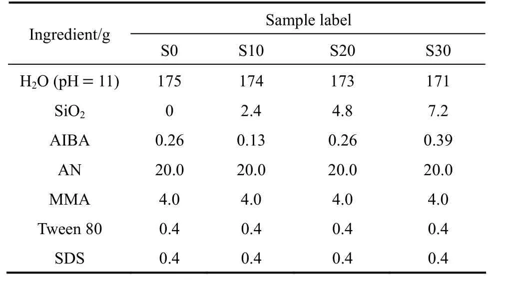
Table 1 Recipes for emulsion polymerizations of AN-MMA in the presence of AIBA adsorbed silica particles
2.3 Preparation of mesoporous carbon
The AN-MMA copolymer/silica nanocomposite powder was obtained by coagulating the resultant AN-MMA copolymer/silica nanocomposite latex, filtering, washing and drying at 65 °C. The nanocomposite powder was carbonized under pure N2atmosphere at 800 °C for 1 h to achieve complete carbonization of AN copolymer. Then, the obtained carbon/silica nanocomposites were dispersed in HF aqueous solution [10% (by mass)] for 24 h to remove the silica. The desired mesoporous carbon materials were obtained after separating, washing with distilled water and drying.
2.4 Characterization
Thermogravimetric analysis (TGA) of AN-MMA copolymer/silica nanocomposites was conducted to determine the carbon yield under nitrogen atmosphere using a Pyris1 TGA thermogravimetric instrument (Perkin-Elmer Co. USA). The heating rate was set at 20 °C·min−1, and temperature was ranged from room temperature to 800 °C.
Nitrogen adsorption-desorption isotherms of carbon materials were measured by using an Autosorb-1-C analyzer (Quantachrome Instruments Co., USA) at 77.4 K. The carbon samples were degassed undervacum at 200 °C for at least 3 h prior to the nitrogen adsorption measurements. The specific surface area was calculated from the adsorption data in the relative pressure below 0.3 using the Brunauer-Emmett-Teller (BET) method, and the mesopore size distribution curve were calculated by the Barrett-Joyner-Halenda (BJH) method from the desorption result [20]. The total pore volume and micro-pore volume were calculated from the amount of absorbed nitrogen (in the liquid state) at the highest relative pressure (P/P0) and at P/P0=0.1.
A Nexus 670 Fourier transform infrared (FT-IR) spectrometer was used to characterize the composition of the samples. X-ray diffraction (XRD) patterns of mesoporous carbons were determined using a Shimadzu XRD-6000 X-ray diffractometer at 40 kV and 36 mA, using CuKαradiation (k=0.1506 nm), at 2θ=4°·min−1between 15° and 70°.
The morphology of mesoporous carbon materials was observed by using a 1230EX type transmission electron microscope (TEM, JEOL Co., Japan) and a S-4800 type scanning electron microscopy (SEM, Hitachi Co., Japan).
3 RESUL TS AND DISCUSSION
3.1 Thermal decomposition of AN-MMA copolymer/silica nanocomposites
The previous papers showed that most of added AIBA could be absorbed onto silica at pH=11 through the electrostatic action, and the encapsulation of silica by polymer could be achieved through the polymerization initiated by absorbed AIBA initiator [21, 22]. Under polymerization conditions of Table 1, the conversion of monomers to polymer was determined by the weighing method. The mass percentages of copolymer and silica in the nanocomposite (wcopolymerand wsilica) calculated from the feed mass percentages of silica and monomers, and the conversion are shown in Table 2. It can be seen that the monomers conversion of in-situ emulsion polymerization is increased as the usage of AIBA increased, but the conversion of in-situ emulsion polymerization is lower than that of conventional emulsion (Sample S0) at the same usage of AIBA.
The residual mass percentages (wresidual) of AN-MMA copolymer and AN-MMA copolymer/silica nanocomposites determined by TGA are also shown in Table 2. The carbon yields of AN-MMA copolymers calculated by

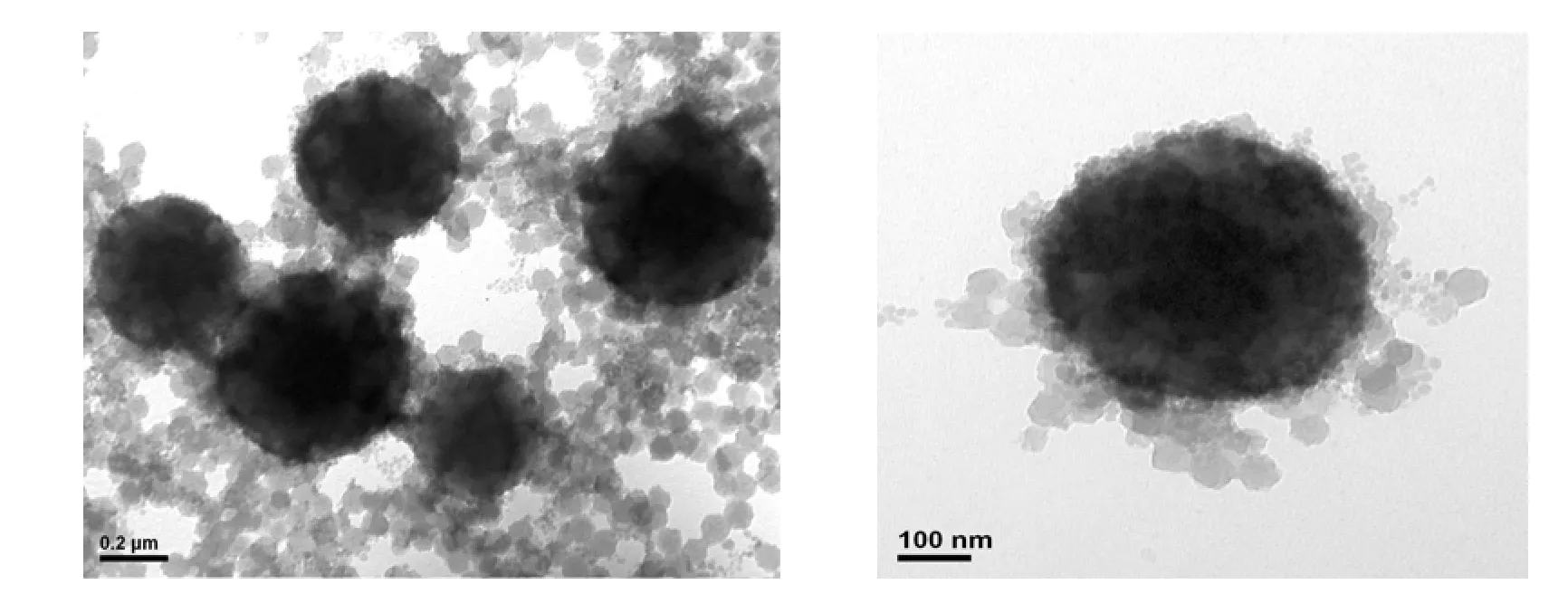
Figure 1 Typical TEM micrographs of AN-MMA copolymer/silica nanocomposite latex particles S20
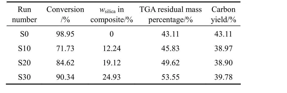
Table 2 TGA result and carbon yields of AN-MMA copolymer/silica nanocomposites with different compositions
are also shown in Table 2.
In Eq. (1), x is the residual mass percentage of pure silica and equal to 95% as obtained from TGA analysis. It can be seen that the carbon yield of AN-MMA copolymer in the nanocomposite is slightly lower than that of pure AN-MMA copolymer. The incorporation of silica nanoparticles may change the thermal decomposition process of AN-MMA copolymer, and cause the decrease of carbon yield.
The typical TEM micrographs of AN-MMA copolymer/silica nanocomposite latex particles are shown in Fig. 1. It can be seen that the obtained nanocomposite latex comprises big particles with size of greater than 200 nm, and small particles with size of about 25 nm. Due to the presence of encapsulated silica particles, the big particles show dark in TEM micrographs. The size of most small particles is greater than the size of original silica colloidal particles, indicated the coating of copolymer onto them. It is expected that both encapsulated and coated silica particles would be acted as templates during the formation of porous carbon.

Figure 2 Infrared spectra of (1) pure silica, (2) AN-MMA copolymer/silica nanocomposite (S20), (3) carbon/silica composite S20, (4) carbon S20 after HF etching
3.2 Composition change during preparation process of mesoporous carbon
Figure 2 shows FT-IR spectra of silica, AN-MMA copolymer/silica nanocomposite, carbon/silica composite, and carbon material obtained after HF etching. It can be seen that pure silica exhibits the characteristic bands at 1112.7 cm−1and 476.6 cm−1assigned to SiOSi asymmetric and bending vibrations, respectively. Other bands appeared at 800.7 cm−1, 1603.3 cm−1and 3432.2 cm−1are assigned to SiOSi elastic stretching vibrations. AN-MMA copolymer/silica nanocomposite exhibits all the characteristic bands of silica, and absorption bands at 2359.2 cm−1, 2245.1 cm−1, 1629.3 cm−1corresponding to CN bond, and a band at 1727.7 cm−1corresponding to CO bond. From the FT-IR spectrum of carbon/silica composite obtained by carbonization of AN-MMA copolymer/silica nanocomposite, it can be seen that the characteristic absorption bands of AN-MMA copolymer disappear, and the characteristic bands of silica still remain. After removal of the silica template, the characteristic bands of silica also disappear, demonstrating the completely removal of silica template by HF treatment.
X-ray diffraction (XRD) patterns of the resulted carbon materials are shown in Fig. 3.
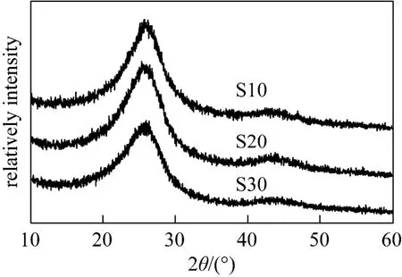
Figure 3 X-ray diffraction patterns of mesoporous carbon prepared: S10, S20, S30
The appearance of a broad characteristic peak at~24° corresponding to (002) reflection and a less intense peak at ~44° corresponding to (101) reflection demonstrates the graphitized structure of the obtained carbon materials. The characteristic patterns of silica do not appear in XRD patterns, also indicating the complete removal of silica from the composite after HF etching.
3.3 Nitrogen adsorption-desorption behavior and pore structure of carbon materials
Figure 4 shows nitrogen adsorption-desorption isotherms of the carbon materials prepared from the pure AN-MMA copolymer and AN-MMA copolymer/ silica nanocomposites with different silica contents.
It can be seen from Fig. 4 (b), 4 (c) and 4 (d) that the nitrogen adsorption-desorption isotherm of the carbon materials prepared by carbonization of AN-MMA copolymer/silica nanocomposites with silica removed by HF etching, exhibit hysteretic loops at great relative pressures (P/P0), indicating the presence of mesopores. While the carbonization products of AN-MMA copolymer [Fig. 4 (a)] and of AN-MMA copolymer/silica nanocomposite without the HF etching exhibit very small hysteretic loops. It can also be seen that the absorption volume of the carbonization product before HF etching is much lower that after HF etching using the same AN-MMA copolymer/silica nanocomposite.
The calculated pore size distributions of carbon materials are shown in Fig. 5.
It can be seen that the carbonization products of AN-MMA copolymer [Fig. 5 (a)] and AN-MMA copolymer/silica nanocomposite without HF etching [in Fig. 5 (c)] show less volume of pores with size greater than 2 nm, while the carbons prepared by carbonization of AN-MMA copolymer/silica nanocomposites exhibit greater pore size distributions in the range of 5-15 nm after removal of silica. The size distribution of pores was in consistent with that of silica particles,demonstrating that silica particles actually act as template in the formation of mesopores in the carbon. So, it is feasible to control the diameter of mesopores in carbon materials using the proposed method.
The porosity parameters of carbons prepared from AN-MMA copolymer and AN-MMA copolymer/ silica nanocomposites with different silica contents are shown in Table 3. It can be seen that the mean pore size and the total pore volume of carbons increase as the silica content in AN-MMA copolymer/silica nanocomposites increased from 12.24% to 24.93%. The mean pore size and the total pore volume of carbon sample S30 are much greater than that of carbons S10 and S20, while SBETof carbon S30 is lower than that of carbon S20. This should be caused by the aggregation of silica nanoparticles when the content of incorporated silica particles is greater.
Jang et al. [12] prepared PAN/silica naocomposites with the mass fraction of silica closed to 50% by vapor polymerization. The porous carbons obtained after carbonization and removal of silica exhibited BET surface area of 473 m2·g−1, using silica particles with size of 12 nm as templates. The BET surface areas of carbon materials obtained in this work were all greater than that of Jang’s results, even at lower usage of silica templates.
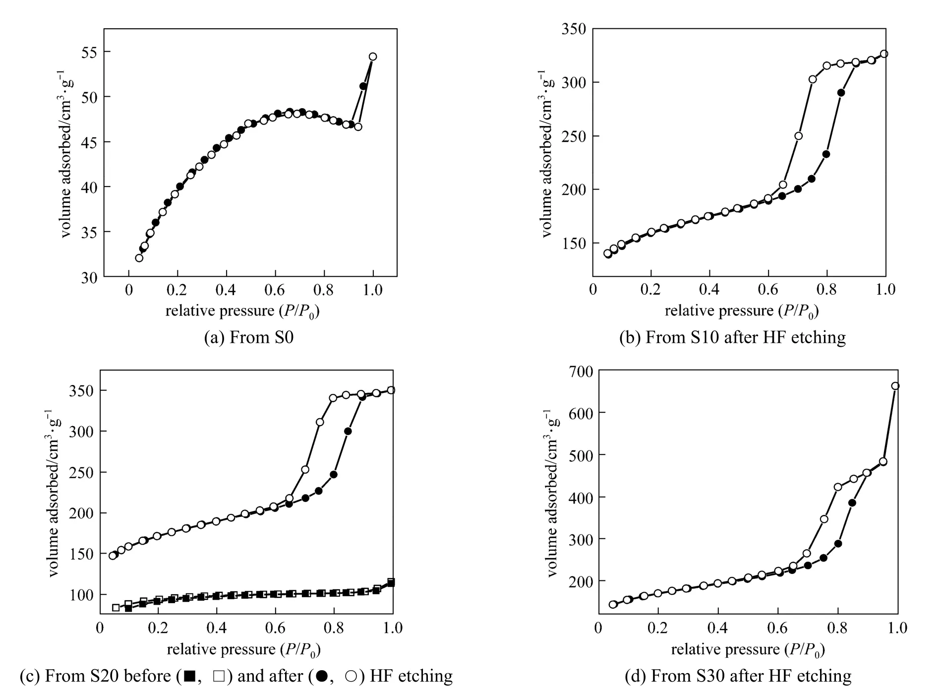
Figure 4 Nitrogen adsorption (solid sy mbol) and desorption(open symbol) isotherms curves of carbon materials obtained by carbonization of products from S0 (a), S10 (b) (after HF etching), S20 (c) (before and after HF etching) and S30 (d) (after HF etching)
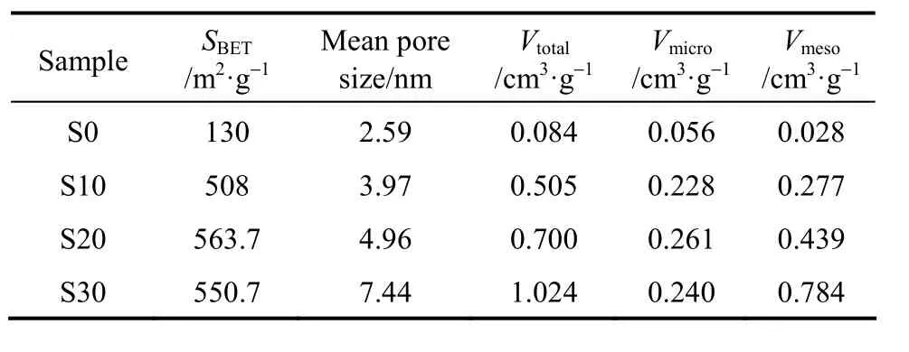
Table 3 Porous textural parameters of carbons prepared from AN-MMA copolymer and its nanocomposites with different silica contents
3.4 Morphology of mesoporous carbon
SEM and TEM micrographs of mesoporous carbons prepared from AN-MMA copolymer/silica nanocomposite with different silica percentages are shown in Figs. 6 and 7, respectively.
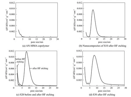
Figure 5 Pore size distributions of carbons obtained by carbonization of AN-MMA copolymer (a), and nanocomposites of S10 (b) (after HF etching), S20 (c) (before and after HF etching) and S30 (d) (after HF etching) runs
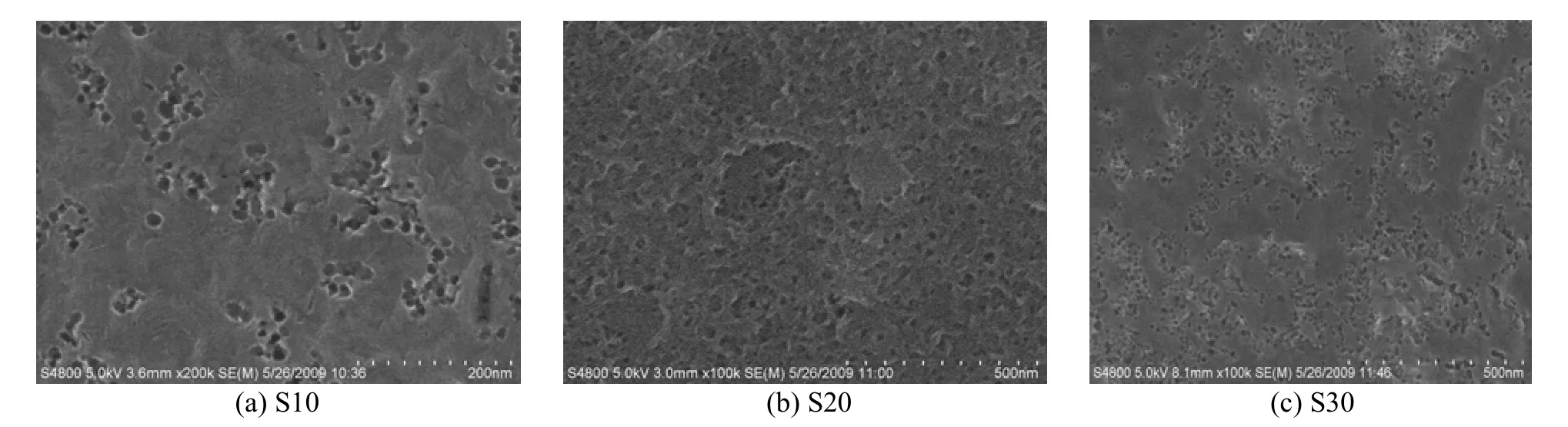
Figure 6 SEM micrographs of mesoporous carbons prepared from AN-MMA copolymer/silica nanocomposites with different silica percentages (a) S10, (b) S20, (c) S30
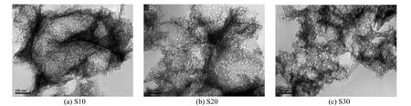
Figure 7 TEM micrographs of mesoporous carbons prepared by AN-MMA copolymer/silica nanocomposites with different silica percentages
From Fig. 6, it can be seen that many mesopores appear at the surface of the resulted carbons, and the number of mesopores increases with the increase of silica contents in polymer/silica nanocomposites. From Fig. 7, it reveals that all the carbons have thetypical morphology of mesoporous materials with 3-dimensionlly interconnected and disordered pore structure. The mesopores are evident in carbon frameworks and entirely close-packed. It demonstrates that the mesopores in the carbons are generated by removal of the silica particles and remained intact during the etching process.
4 CONCLU SIONS
Silica nanoparticles could be effectively encapsulated and well dispersed into AN-MMA copolymer latex particles via in-situ emulsion polymerization initiated by AIBA initiator absorbed onto silica particles. The carbon yield of AN-MMA copolymer was slightly decreased as silica incorporated into the copolymer. The silica nanoparticles template could be completely removed from the carbons by HF etching, and acted as templates to form the mesopores in the AN copolymer-based carbon. The mesoporous carbons with different pore sizes and pore structures could be prepared by varying the mass ratios of silica to AN copolymer, and the resulted carbons exhibited greater BET surface areas than the previous reported PAN-based carbons prepared by silica templating method via vapor polymerization. Due to the aggregation of silica nanoparticles at higher silica content, the obtained carbon showed a widened pore size distribution and decreased surface area. So far, to synthesize AN copolymer/silica nanocomposite with greater silica content and well dispersion of silica are still challenge in preparing mesoporous carbon with greater pore volume and surface area, and narrow pore size distribution through the proposed approach.
REFERENCES
1 Tamai, H., Kakii, T., Hirota, Y., Kumamota, T., Yasuda, H., “Synthesis of extremely large mesoporous activated carbon and its unique adsorption for giant molecules”, Chem. Mater., 8 (2), 454-462 (1996).
2 Joo, J.B., Kim, P., Kim, J., Yi, J., “Advances in catalysis and catalytic materials for energy and environmental protection: Preparation of mesoporous carbon templated by silica particles for use as a catalyst support in polymer electrolyte membrane fuel cells”, Catal. Today, 111 (3-4), 171-175 (2006).
3 Xia, N.N., Zhou, T.X., Mo, S.S., Zhou, S.L., Zou, W.J., Yuan, D.S.,“Supercapacitive behaviors of worm-like mesoporous carbon in non-aqueous electrolyte”, J. Appl. Electrochem., 41 (1), 71-75 (2011).
4 Chai, S., Yoon, S.B., Yu, J.S., Choi, J.H., Sung, Y.E., “Ordered porous carbons with tunable pore sizes as catalyst supports in direct methanol fuel cell”, J. Phys. Chem. B, 108 (22), 7074-7079 (2004).
5 Guo, B.K., Wang, X.Q., Fulvio, P.F., Chi, M.F., Mahurin, S.M., Sun, X.G., Dai, S., “Soft-templated mesoporous carbon-carbon nanotube composites for high performance lithium-ion batteries”, Adv. Mater., 23 (40), 4661-4666 (2011).
6 Li, Z.J., Jaroniec, M., “Colloid-imprinted carbons as stationary phases for reversed-phase liquid chromatography”, Anal. Chem., 76 (18), 5479-5485 (2004).
7 Kim, S.S., Shah, J., Pinnavaia, T.J., “Colloid-imprinted carbons as templates for the nanocasting synthesis of mesoporous ZSM-5 zeolite”, Chem. Mater., 15 (8), 1664-1668 (2003).
8 Lee, J., Kim, J., Hyeon, T., “Recent progress in the synthesis of porous carbon materials”, Adv. Mater., 18 (16), 2073-2094 (2006).
9 Liang, C.D., Li, Z.J., Dai, S., “Mesoporous carbon materials: Synthesis and modification”, Angew. Chem. Int. Ed., 47 (20), 3696-3717 (2008).
10 Han, S., Hyeon, T., “Simple silica-particle template synthesis of mesoporous carbons”, Chem. Commun., 999 (19), 1955-1956 (1999).
11 Jang, J., Lim, B., “Selective fabrication of carbon nanocapsules and mesocellular foams by surface-modified colloidal silica templating”, Adv. Mater., 14 (19), 1390-1393 (2002).
12 Jang, J., Lim, B., Choi, M., “A simple synthesis of mesoporous carbons with tunable mesopores using a colloidal template-mediated vapor deposition polymerization”, Chem. Commun., (33), 4214-4216 (2005).
13 Choma, J., Zawislak, A., Gorka, J., “Synthesis and adsorption properties of colloid-imprinted mesoporous carbons using poly(vinylidene chloride-co-viny chloride) as a carbon precursor”, Adsorption, 15 (1), 167-171 (2009).
14 Ryoo, R., Joo, S.H., Kruk, M., Jaroniec, M., “Ordered mesoporous carbons”, Adv. Mater., 13 (9), 677-681 (2001).
15 Kruk, M., Dufour, B., Celer, E.B., Kowalewski, T., Jaroniec, M., Matyjaszewski, K., “Synthesis of mesoporous carbons using ordered and disordered mesoporous silica templates and polyacrylonitrile as carbon precursor”, J. Phys. Chem. B, 109 (19), 9216-9225 (2005).
16 Kruk, M., Kohlhaas, K.M., Dufour, B., Celer, E.B., Jaroniec, M., Matyjaszewski, K., Ruoff, R. S., Kowalewski, T., “Partially graphitic, high-surface-area mesoporous carbons form polyacrylonitrile templated by ordered and disordered mesoporous silicas”, Micropor. Mesopor. Mater., 102 (1-3), 178-187 (2007).
17 Yang, Z.L., Tang, F.F., Yuan, J.J., Pu, H.T., Luo, Z.Y., Shao, Q.C.,“Preparation and applications of mesoporous carbon materials from polyacrylonitrile”, Polym. Mater. Sci. Eng., 27 (7), 187-190 (2011). (in Chinese)
18 Kawashima, D., Aihara, T., Kobayashi, Y., Kyotani, T., Tomita, A.,“Preparation of mesoporous carbon from orgainc polymer/silica nanocomposite”, Chem. Mater., 12 (11), 3397-3401 (2000).
19 Han, S., Sohn, K., Hyeon, T., “Fabrication of new nanoporous carbons through silica templates and their application to the adsorption of bulky dyes”, Chem. Mater., 12 (11), 3337-3341 (2000).
20 Barrett, E.P., Joyner, L.G., Halenda, P.P., “The determination of pore volume and area distributions in porous substances. I. Computations from nitrogen isotherms”, J. Am. Chem. Soc., 73 (1), 373-380 (1951).
21 Qi, D.M., Bao, Y.Z., Weng, Z.X., Huang, Z.M., “Synthesis and characterization of poly(butyl acrylate) /silica and poly(butyl acrylate)/silica/poly(methyl methacrylate) composite particles”, J. Appl. Polym. Sci., 99 (6), 3425-3432 (2006).
22 Qi, D.M., Bao, Y.Z, Weng, Z.X., Huang, Z.M., “Anchoring of polyacrylate onto silica and formation of polyacrylate/silica nanocomposite particles via in situ emulsion polymerization”, Colloid Polym. Sci., 286 (2), 233-241 (2008).
2011-05-22, accepted 2011-11-02.
* Supported by the Program for New Century Excellent Talents in University (NCET-07-0738).
** To whom correspondence should be addressed. E-mail: yongzhongbao@zju.edu.cn
 Chinese Journal of Chemical Engineering2013年6期
- Chinese Journal of Chemical Engineering的其它文章
- Adsorption and Desorption Behavior of Tannic Acid in Aqueous Solution on Polyaniline Adsorbent*
- Synthesis of 2-Methyl-4-methoxyaniline from o-Nitrotoluene Using Pt/C and Acidic Ionic Liquid as Catalyst System*
- Supercritical Fluid Extraction of a Novel Template from Mesoporous Zirconia and the Effect on Porous Structure*
- Effect of Hydrogen Reduction of Silver Ions on the Performance and Structure of New Solid Polymer Electrolyte PEI/Pebax2533/AgBF4Composite Membranes*
- Comparison on Thermal Conductivity and Permeability of Granular and Consolidated Activated Carbon for Refrigeration*
- Immobilization of Papain in Biosilica Matrix and Its Catalytic Property*