
An iterative Rankine BEM for wave-making analysis of submerged and surfacepiercing bodies in finite water depth*
2013-06-01 12:29HEGuanghua
水动力学研究与进展 B辑 2013年6期
HE Guanghua
Department of Naval Architecture and Ocean Engineering, Osaka University, Suita, Osaka, Japan,
E-mail: he@naoe.eng.osaka-u.ac.jp
An iterative Rankine BEM for wave-making analysis of submerged and surfacepiercing bodies in finite water depth*
HE Guanghua
Department of Naval Architecture and Ocean Engineering, Osaka University, Suita, Osaka, Japan,
E-mail: he@naoe.eng.osaka-u.ac.jp
(Received May 23, 2013, Revised July 10, 2013)
A 3-D iterative Rankine Boundary Element Method (BEM) for seakeeping problem in time domain is developed in the framework of linear potential theory. Waves generated by both submerged and surface-piercing bodies moving at a constant forward speed in otherwise calm water, and the resultant steady wave pattern, wave profile and resistance are computed to validate this newly-developed code. A rectangular computational domain moving with the same forward speed as the body is introduced, in which an artificial damping beach is installed at an outer portion of the free surface except the downstream side for satisfying the radiation condition. The velocity potential on the ship hull and the normal velocity on the free surface are obtained directly by solving the boundary integral equation, with the Rankine source used as the kernel function. An iterative time-marching scheme is employed for updating both kinematic and dynamic free surface boundary conditions to stabilize the calculation. Extensive results including the wave patterns, wave profiles and wave resistances for a submerged spheroid and a Wigley hull with forward speed are presented to validate the efficiency of the proposed 3-D time-domain higher-order approach. Finally, the sensitivity of ship-generated waves to the water depth is investigated. Computed results show satisfactory agreement with the corresponding experimental data and other numerical solutions.
wave resistance, wave pattern, time-domain, Boundary Element Method (BEM), iterative method
Introduction
The wave-making problem of the steady ship is one of the classic research topics in ship hydrodynamics, since prediction and minimization of wave resistance in the ship design stage are very important. One of the most popular methods is the potential-flowbased method, since it is more practical and efficient than CFD. This is also the case in the present paper. The strip-theory methods have been widely used for predicting wave loads and ship motions in industry, because of its advantage of being fast, reliable, and easy to implement. Due to its drawbacks in predicting local pressures and global wave loads for high speed vessels and flared hull forms at lower frequencies, the development of advanced 3-D methods has been expected by both engineers and scholars. Thanks to rapid evolution in the computing capability and technology in the last two decades, 3-D computation codes are becoming popular in the seakeeping research. So far, the 3-D methods developed for seakeeping analyses can be categorized into two major groups: the free-surface Green-function method and the Rankine panel method. It is well known that in the time-domain analysis, especially for body-nonlinear problems, the free-surface temporal Green-function method is time-consuming in long-term computations due to convolution nature of the integral[1].
The Rankine panel method has been widely applied to steady wave resistance and seakeeping problems nowadays. A computer code, named ship wave analysis (SWAN), has been developed by Nakos[2], Kring[3]and Huang[4]. Another code, named as waveinduced loads and ship motion (WISH), was recently developed by Kim et al.[5]for the time-domain seakeeping analyses using the Rankine panel method. Zhang and Beck[6]studied the steady ship-wave problems by means of the so-called desingularized source method. Kara et al.[7]calculated the wave pattern and wave resistance as a full nonlinear 3-D problem in time domain using the Rankine source method. Zhang et al.[8]applied the Rankine source method to ship-form optimization based on the calculation of wave resistance. For the steady ship-wave analysis, it has been reported by Kring[3], Yasukawa[9], Kara et al.[7], Zhang and Beck[6], Yang et al.[10]and so forth, in time domain, while the frequency-domain studies have been reported by Yasukawa[11], Nakos[2], Raven[12], Tarafder and Suzuki[13], Bal[14], Belibassakis et al.[15]and so forth. An advantage of the Rankine panel method is the flexibility in treatment of the free surface, allowing more complicated free-surface conditions. Conversely a disadvantage of the Rankine panel method is the necessity of discretization of the free surface surrounding the body, which increases the number of unknowns and also introduces the numerical dispersion, dissipation, and instability.
In the present paper, a higher-order Boundary Element Method (BEM), with the Rankine source used as the kernel function, is proposed due to its advantage of being flexible and suitable even for complicated geometries and multi-bodies, without increasing difficulty in the computer code. This newly-developed 3-D time-domain higher-order Rankine BEM is applied to the steady ship-wave problem. In the present numerical model, a direct boundary integralequation method[16]is extended and adopted, in which unknowns are the velocity potential on the ship hull and the normal velocity on the free surface. A rectangular computational domain moving with the same forward speed as the body is introduced, and only half of the computational domain is used due to the geometric symmetry of the body. An artificial damping beach is installed at the outer portion of the truncated free surface except the downstream side, to prevent the wave reflection from the outer boundary of the computational domain. Extensive results including the wave patterns, waves and wave resistances for a submerged spheroid and a Wigley hull with forward speed are presented, and compared with the corresponding experimental data and other numerical solutions. Finally, the sensitivity of ship-generated waves to the water depth is studied. It is confirmed that the present time-domain method can be used to calculate the wave-making problem for both submerged and surface-piercing bodies in satisfactory precision.
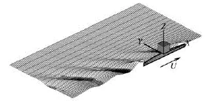
Fig.1 Coordinate system in the analysis
1. Mathematical formulation
1.1Statement of general problem
As was mentioned previously, a higher-order Rankine BEM is proposed in view of numerical accuracy and computational efficiency for complicated geometries and multi-bodies. A Cartesian coordinate system, (x,y,z), fixed to a ship in steady motion is introduced (see Fig.1). The horizontalxoyplane is set on the still water surface with its origin placed on the center of the body, and thez-axis is positive upward. A ship is translating at the constant forward speedUwith respect to a space-fixed reference frame (x0,y0,z0). The fluid is assumed to be incompressible and inviscid with irrotational motion. Then the velocity potential can be introduced and the total potential is divided into basis potentialΦb, disturbed potentialφd, and incident-wave potentialφI:
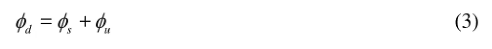
whereζis the elevation of free surface, subscripts, andb,dandIdenote the basis, disturbed and incident-wave flows, respectively. The basis flow is assumed to be the largest component with its orderΦb=O(1), and the disturbed,φd, and incident,φI, flows are assumed small with the orderO(ε). The disturbed flow can be further divided into the steady flowφs, and unsteady flowφu
The basis flow is expressed as

This flow can be either Neumann-Kelvin flow or double-body flow. For the former case, only the uniform flow is considered, while the double-body flow should satisfy the following boundary conditions on the free surface(SF) and on the body surface(SB):
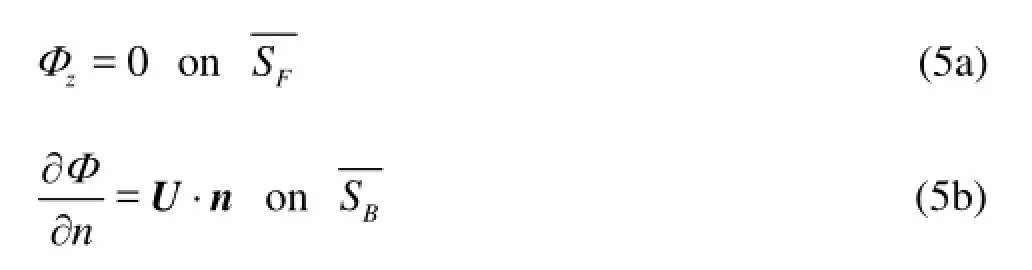
wherendenotes the normal vector, which is defined positive when pointing into body from the boundarysurface.
The disturbed potentialdφis also governed by the Laplace equation with the following boundary and initial conditions:
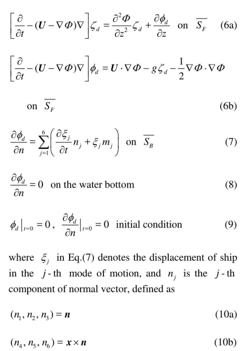
andmjdenotes thej-th component of the so-calledm-term, which can be expressed as
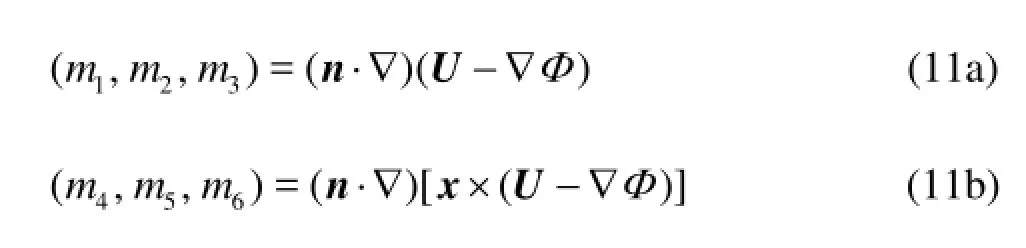
The -mterms provide coupling effects between the basis and unsteady flows. These terms tend to be larger near the ends of the ship. For the Neumann-Kelvin linearization, the -mterms can be simplified as follows:
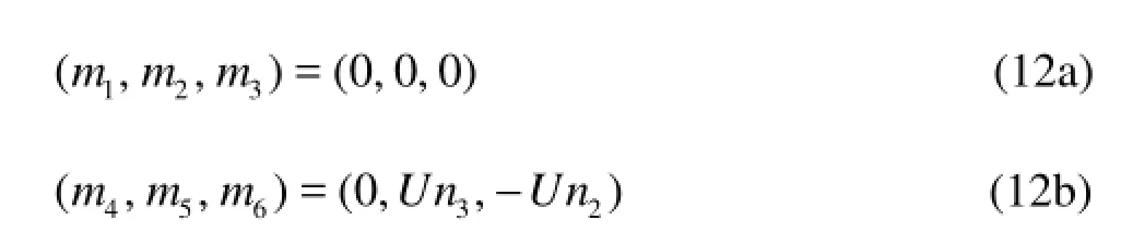
1.2Steady problem
For the steady ship-wave problem in the Neumann-Kelvin linearization, it is assumed that the ship is advancing at a constant forward speed in still
water without any oscillation. In other words, the steady wave problem of a ship fixed in sinkage and trim is considered. Equations (6) can then be simplified as follows:
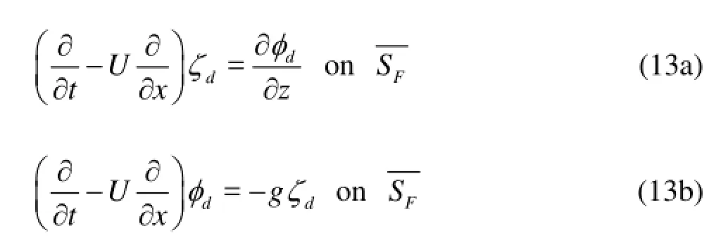
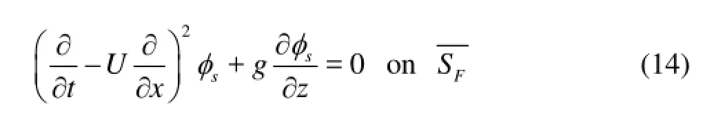
For the steady wave problem, the disturbed potential is just the steady potential (φs=φd). By eliminating the wave elevationζdin Eqs.(13) and combining into a single equation, the well-known linearized free-surface condition in the Neumann-Kelvin problem is recovered in the form
1.3Linearized pressure
By using the decomposed form of the total potentialΨin Eq.(1), the pressure on the body is expressed as
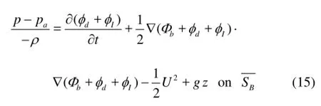
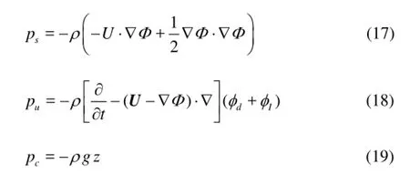
We may setpa=0 for convenience, and then the linearized pressure is decomposed into the steady pressure componentps, unsteady componentpuand hydrostatic componentpcin the following form:

where
A generalized force can be obtained by the pressure integral on the wetted surface of the body as follows
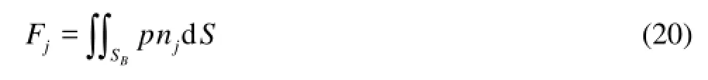
wherejnis the -thjcomponent of generalized normal vector, defined in Eq.(10).
2. Numerical implementation
2.1Boundary integral equation
The higher-order BEM has been widely used to solve the hydrodynamics problems in ocean engineering and ship engineering due to its high accuracy and fast convergence, such as Kashiwagi[17], Bai and Eatock Taylor[18], He and Kashiwagi[19,20]and so forth. A 9-node quadric iso-parametric element is used to discretize both body surface and free surface in the present study. By introducing the shape functionsjNin each element, the position coordinate and velocity potential can be written in the following forms:
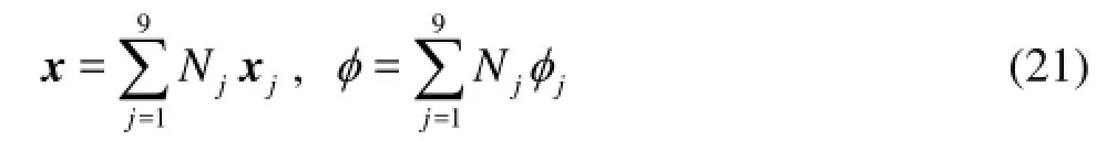
wherejdenotes the local node number, andjxandjφare the nodal positions and velocity potentials at 9 nodes on an element under consideration, respectively.
A boundary integral equation for the potential components,Φanddφover the whole boundary surfacesTScan be derived through Green’s second identity in the form
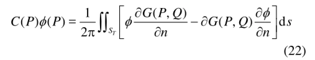
wherePis a field point,Qis a source point, ()CPis the solid angle at the field pointP, the normal vectornpoints out from the surface of computational domain.
A simple Rankine source with its mirror image reflected by the water bottom surface is adopted as the Green function as follows:
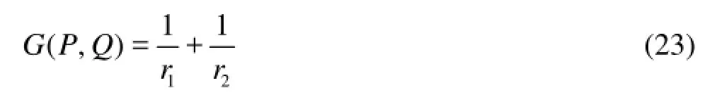
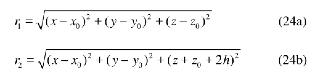
where Here,hdenotes the water depth. With this Green function and the boundary condition of Eq.(8), the integral on the water bottom can be zero and thus removed.
The discretized form of the boundary integral equation can be written as
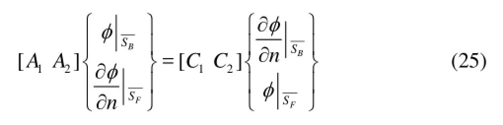
where the influence coefficients1A,2Aand1C,2Cin the matrices in Eq.(25) are computed with higherorder boundary element method of quadratic order. The velocity potential on the body surface and the normal velocity on the free surface are unknowns; these are actually their values at nodal points of quadratic panels and can be determined by solving the boundary integral equation (BIE), Eq.(25). After these have been determined, the velocity potential and position on the free surface are then updated from Eqs.(13) in the time-marching scheme.
2.2Numerical damping beach
For satisfying the radiation condition, a numerical damping beach is installed to prevent the wave reflection from the end of truncated computational domain. The damping beach employed by Nakos[2], Kring[3], and Huang[4]is also adopted in the present study. The cooling terms of damping beach are included only in the kinematic free-surface condition and thus the free-surface condition is modified as follows:
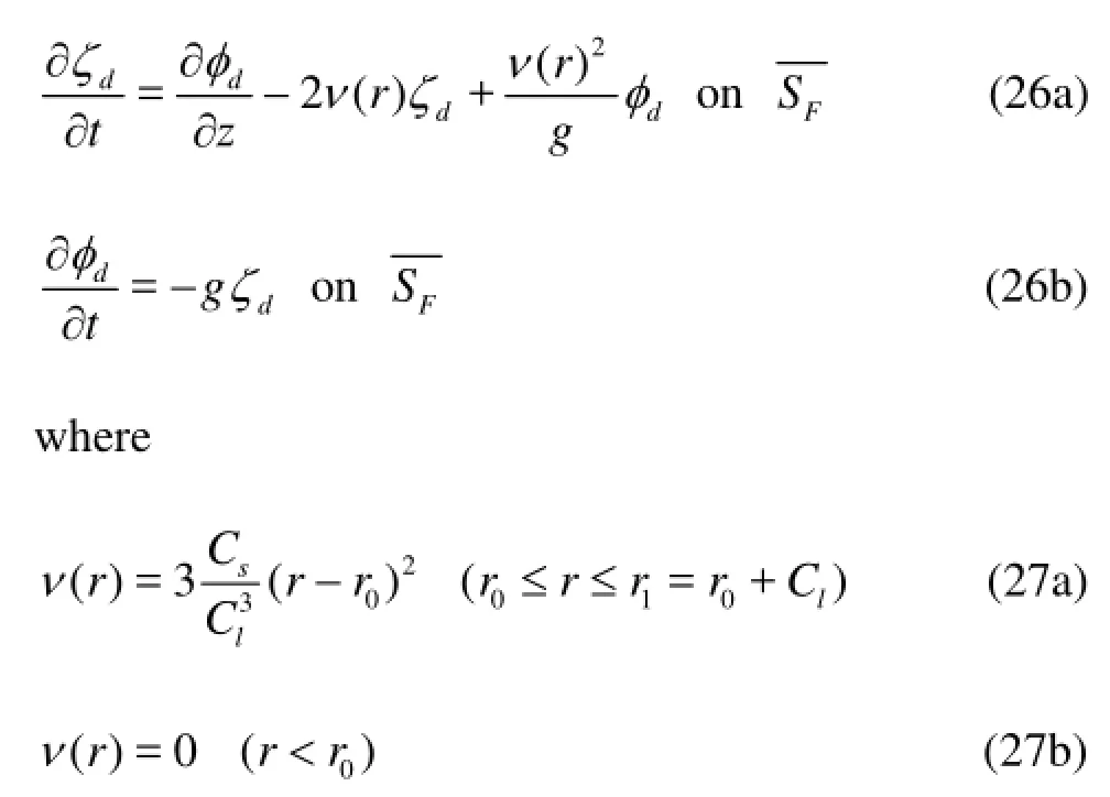
and ()rνis the coefficient of the damping beach, which is determined by the strengthsCand the lengthCiof the damping beach. For zero-speed and low forward speed problems, numerical damping beach is installed at all sides of the outer portion of the free surface, since disturbed waves propagate slowly towards all directions. For high forward speed problems,the implementation of numerical damping beach is not necessary for the downstream side, since the disturbed wave propagates out very fast.
2.3Iterative time marching
The time-marching procedure for simulating a steady ship-wave problem used in this study is described in this subsection. For numerical stability and accuracy, an iterative time-marching scheme is employed for updating the free surface (Eqs.(13)). Details of the iterative time-marching scheme are stated as follows:
(1) Assume time derivatives of wave elevation, (ζk+1)*, and velocity potential, (φk+1)*on free surface at (k+1)-th time step by using values atk-th step as initial values. Here, the subscripttdenotes the time derivative, the superscripts*the initial guess, (k+1) the (k+1)-th time step.
(2) Predict wave elevation,ζk+1, and velocity potential,φk+1on free surface at (k+1)-thtime step by using the Crank-Nicolson method,
wheretΔ is time increment.
(3) Solve the BIE in Eq.(25) by using the LU decomposition method, and then obtain the normal velocity on the free surface and the velocity potential on the body surface.
(4) Use Eqs.(13) to update the free surface, and then newly obtainζtk+1andφtk+1.
It is well known that the iterative scheme always has advantages of high accuracy and good numerical stability, and has a disadvantage of CPU time-consuming. Under the assumption of linear theory, the influence matrices are only constructed once and kept the same through the simulation. So only the back substitution step of LU decomposition method is needed for solving the BIE in Eq.(25), which is very fast and not CPU time-consuming.
3. Numerical results
The waves generated by a submerged prolate spheroid and a Wigley ship advancing in still water at constant forward speed are simulated. For keeping numerical simulation stable, the forward speed of the body is gradually increased from a state of rest to a specified constant value ofU. As was mentioned previously, the sinkage and trim are not considered in the present study.
A rectangular computational domain is introduced and truncated at some distance from the ship, and the damping beach is installed at the outer portion of the free surface, except the downstream side. The implementation of damping beach is not necessary for the downstream side, since the disturbed wave propagates out so fast in the present case. As was mentioned before, the damping beaches are necessary for all directions for zero-speed or low forward speed problems. For saving CPU time, only half domain is used for numerical computations, since the flow around a symmetric body is naturally symmetric about thexozplane.
3.1A submerged prolate spheriod
As was mentioned previously, the body is started from a state of rest and reaches a constant speed,Fr=0.35, and then kept steady state in subsequent computations. This phenomenon can be clearly seen from the evolution of wave patterns with respect totime as shown in Fig.2. In the contour line, positive values are shown with solid line, while negative values are shown by dotted line. Figure 3 shows the corresponding wave pattern generated by the spheroid at some time instant, after the steady state has been achieved.
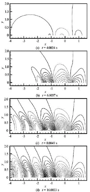
Fig.2 Snapshots of wave elevation contours generated by the submerged prolate spheroid advancing with a forward speed, started generally from rest to =Fr0.35 (=t4, 6, 8, and 16)
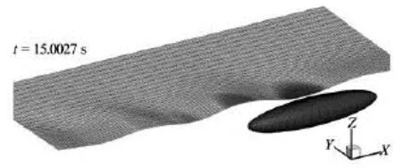
Fig.3 Wave pattern and for the submerged prolate spheroid advancing with forward speed of =Fr0.35
From Figs.2, 3, it can be seen that the wave patterns are quite realistic, and no waves are reflected from all boundaries of the computational domain, which confirms that the damping beach is effective enough and the length of downstream and upstream is also long enough.
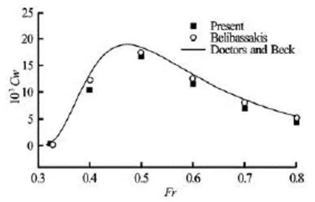
Fig.4 Wave resistance of the prolate spheroid with the submerged depth /=HL0.16
Figure 4 shows the resistance of the proplate spheroid for several Froude numbers. And the corresponding solutions reported by Doctors and Beck[21]and Belibassakis et al.[15]are also shown in Fig.4 for comparison. It can be found from Fig.4 that numerical results obtained by the present computational model show satisfactory agreement with the reference solutions, except an under-prediction at =Fr0.4.
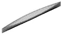
Fig.5 Mesh on the Wigley hull
3.2A Wigley hull
The standard Wigley model can be expressed mathematically as follows
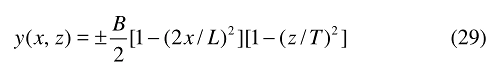
whereL,B,dare the length, breadth, and standard draft of the ship, respectively. In the present study, the ship length isL=2.0 m with length-to-beam ratioL/B=10 and beam-to-draft ratioB/d=1.6. Both body and free surfaces are discretized with 9-node quadratic quadrilateral panels. An example of the mesh on wetted mean Wigley hull is shown in Fig.5. The computational time by using the present iterative time-marching scheme is compared with another numerical scheme, which is an explicit time-marching scheme imbedded with an upwind finite differencemethod. Calculations were carried out on a personal computer with totally 4366 nodes, which is the typical mesh used in the following simulations. Computational time with the number of time-step total to 2400 is about 4.5 h for the iterative time-marching scheme and 3.2 h for the explicit time marching scheme.
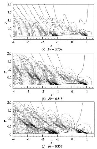
Fig.6 Wave patterns for the Wigley hull advancing with various forward speeds
3.2.1 Wave pattern and wave profile
Figure 6 shows the wave contours resulting from the steady forward motions of the Wigley hull at forward speedsFr=0.266, 0.313, and 0.350, respectively. In the contour line, positive values are shown with solid line, while negative values are shown by dotted line. Andx=0 is set as the mid of the hull,x=–1.0 andx=1.0 are the stern and bow of the ship. Figure 7 shows a comparison of wave profiles along the surface of Wigley hull among the present numerical results, experimental data and Gadd numerical solutions atFr=0.266, 0.313, and 0.350, respectively. Both experimental data and Gadd numerical solution are available in Gadd[22].
It can be seen from Fig.7 that the present results are in satisfactory agreement with other results. Good agreement of the phase between the present results and other solutions is found, while the magnitude of wave elevation near the first crest and trough from the bow of ship in the present numerical results is smaller than the measured data. The difference between computed and measured wave profiles was also reported by Gadd[22]and Shahjada Tarafder and Suzuki[13], Yang et al.[10]. That can be considered that this discrepancy is attributed to the nonlinear effects, because the present results are obtained with the linear potential code. Raven[12]proved that the well-known under-prediction of diverging waves by linearised method is caused by neglecting nonlinear effects. And including nonlinear terms could consistently improve the results.
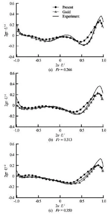
Fig.7 Comparison of wave profile along the Wigley hull between the present numerical results and other solutions for various Froude numbers; measured data from Gadd[18]
3.2.2 Sensitivity of ship wave to the water depth
Ship waves and resistance are quite sensitive to the effect of the water depth and the restricted width of the water area (e.g., in a river or canal). These effects have been studied by Havelock[23]and Tarafder[24]. The present numerical model has ability to simulate both the cases of deep water and shallow water. Thesensitivity of the wave-making to the water depth is studied by investigating wave profiles for various water depths and Froude numbers.
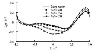
Fig.8 Wave profile along the Wigley hull with various depths of water
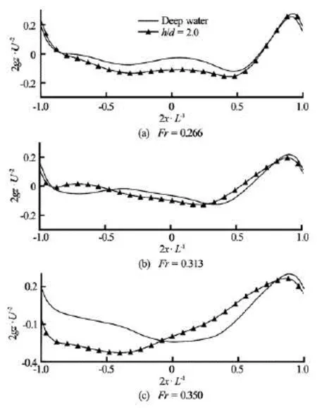
Fig.9 Comparison of wave profiles along the Wigley hull in deep and shallow water (h/d=2.0) with various forrd speeds
Figure 8 shows wave profiles along the hull with different water depths at a specified forward speed,Fr=0.313. The treatment of the “deep water” shown in Fig.8 is by setting a large value to the water depthh. In the present case, the non-dimensional water depth is set equal to /=hd40.0. From Fig.8, it can be seen that: (1) the effect of water depth on the wave profile is obvious, and the influence becomes stronger when the water depth becomes shallow, (2) as the water depth /hd>4, the effect of the water depth becomes very smaller, also indicating that the water depth of /=hd40.0 can be considered as the case of the “Deep water”, (3) the generated waves become steeper from deep to shallow water.
Wave profiles along the hull in deep and shallow water are shown in Fig.9 for three different forward speeds. From Fig.9, it can be obviously seen that (1) a big difference between the deep and shallow water (h/d=2.0) is found, especially for the locations around the amidships and stern, (2) the discrepancy between the deep and shallow water increases, as the ship speed increased.
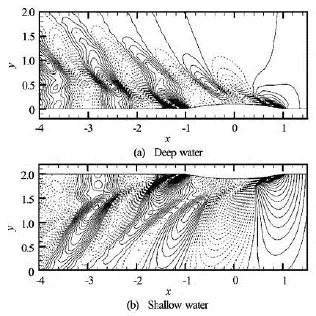
Fig.10 Wave patterns generated by the Wigley hull in deep water and shallow water (h/d=2.0)
Finally, the influence of water depth to the wavemaking problem at forward speedFr=0.313 is illustrated in Fig.10 by showing a comparison of the wave contours between deep and shallow water (h/d=2.0). From Fig.10, it can be found that (1) the difference of the wave pattern between these two cases is apparent, (2) the ship-generated waves become larger, and propagate much farther as the water depth becomes shallow, (3) the length of the transverse waves in the downstream becomes longer due to the effect of shallow water.
4. Discussion and conclusion
A 3-D time-domain method with an iterative procedure based on a higher-order BEM has been proposed and developed in the framework of linear potential theory. This numerical model has been applied to the solution of the BIE associated with the linearized Neumann-Kelvin problem, with application to the wave-making problem of a ship and a submerged body at constant forward speed. First, the evolution of waves generated by the submerged prolate spheroid model that starts from a state of rest and attains to a steady constant speed is calculated. The resistance onthe spheroid for various Froude numbers is validated by comparing with the reference solutions. Then, the present method was applied to the Wigley hull. Computed wave profiles along the Wigley hull at several different Froude numbers are then plotted, and compared with the available reference solutions in favorable agreement. Finally, the sensitivity of ship waves to the water depth and forward speed is studied by showing wave profiles with different water depths and Froude numbers. From these extensive results, it can be concluded that the present numerical model can be used for calculating wave-making problem with satisfactory accuracy.
Acknowledgements
This work was partially sponsored by the Fundamental Research Developing Association for Shipbuilding and Offshore (REDAS), and the Special Coordination Funds for Promoting Science and Technology, Ministry of Education, Culture, Sports, Science and Technology (MEXT), Japan. We thank the reviewers for their kind comments and excellent suggestions.
[1] DATTA R., SEN D. A B-spline solver for the forwardspeed diffraction problem of a floating body in the time domain[J].Applied Ocean Research,2006, 28(2): 147-160.
[2] NAKOS D. E. Ship wave patterns and motions by a three dimensional Rankine panel method[D]. Doctoral Thesis, Cambridge, Massachusetts, USA: Massachusetts Institute of Technology, 1990.
[3] KRING D. C. Ship motions by a three-dimensional Rankine panel method[D]. Doctoral Thesis, Cambridge, Massachusetts, USA: Massachusetts Institute of Technology, 1994.
[4] HUANG Y. Nonlinear ship motions by a Rankine panel method[D]. Doctoral Thesis, Cambridge, Massachusetts, USA: Massachusetts Institute of Technology, 1998.
[5] KIM Y. H., KIM K. H. and KIM J. H. et al. Time-domain analysis of nonlinear motion responses and structural loads on ships and offshore structures: Development of WISH programs[J].International Journal of Naval Architecture and Ocean Engineering,2011, 3(1): 37-52.
[6] ZHANG X., BECK R. F. Three-dimensional large amplitude body motions in waves[J].Journal of Offshore Mechanics and Arctic Engineering,2008. 130(4): 041603.
[7] KARA F., TANG C. Q. and VASSALOS D. Time domain three dimensional fully nonlinear computations of steady body-wave interaction problem[J].Ocean Engineering,2007, 34(5-6): 776-789.
[8] ZHANG Bao-ji, MA Kun and JI Zhuo-shang. The optimization of the hull form with the minimum wave making resistance based on Rankine source method[J].Journal of Hydrodynamics,2009, 21(2): 227-284.
[9] YASUKAWA H. Time domain analysis of ship motions in waves using BEM (1st report: Computation of hydrodynamic forces)[J].Transactions-West Japan Society of Naval Architects,2000, 100: 83-98.
[10] YANG Xiang-hui, YE Heng-kui and FENG Da-kui et al. Computational research on wave making of moving Wigley hull in time domain[J].Journal of Hydrodynamics,2008, 20(4): 469-476.
[11] YASUKAWA H. A Rankine panel method to calculate steady wave-making resistance of a ship taking the effect of sinkage and trim into account[J].Journal of the Society of Naval Architects of Japan,1993, 86: 27-35.
[12] RAVEN H. C. Nonlinear ship wave calculations using the RAPID method[C].Sixth International Conference on Numerical Ship Hydrodynamics.Iowa, USA, 1994, 95-118.
[13] TARAFDER S. Md., SUZUKI K. Numerical calculation of free-surface potential flow around a ship using the modified rankine source panel method[J].Ocean Engineering,2008, 35(5-6): 536-544.
[14] BAL S. Prediction of wave pattern and wave resistance of surface piercing bodies by a boundary element method[J].International Journal for Numerical Methods in Fluids,2008, 56(3): 305-329.
[15] BELIBASSAKIS K. A., GEROSTATHIS Th. P. and KOSTAS K. V. et al. A BEM-isogeometric method for the ship wave-resistance problem[J].Ocean Engineering,2013, 60: 53-67.
[16] HE G., KASHIWAGI M. Numerical analysis of the hydroelastic behavior of a vertical plate due to solitary waves[J].Journal of Marine Science and Technology,2012, 17(2): 154-167.
[17] KASHIWAGI M. A calculation method for steady drift force and moment on multiple bodies[J].Bulletin Research Institute for Applied Mechanics,1995, 170: 83-98.
[18] BAI W., EATOCK TAYLOR R. Higher-order boundary element simulation of fully nonlinear wave radiation by oscillating vertical cylinders[J].Applied Ocean Research,2006, 28(4): 247-265.
[19] HE G., KASHIWAGI M. Nonlinear solution for vibration of a vertical plate and transient waves generated by wave impact[J].The International Society of Offshore and Polar Engineers,2009, 19(3): 189-197.
[20] HE G., KASHIWAGI M. Nonlinear solution for vibration of vertical elastic plate by initial elevation of free surface[J].The International Society of Offshore and Polar Engineers,2010, 20(1): 34-40.
[21] DOCTORS L. J., BECK R. F. Convergence properties of the Neumann-Kelvin problem for a submerged body[J].Journal of Ship Research,1987, 31(4): 227-234.
[22] GADD G. E. Contribution to workshop on ship wave resistance computations[C].Proceedings of the Workshop on Ship Wave-Resistance Computations.Bethesda, Maryland, USA, 1979, 2: 117-161.
[23] HAVELOCK T. H. The effect of shallow water on wave resistance[J].Proceedins of the Royal Society London Series A,1922, 100(706): 499-505.
[24] TARAFDER S. Md. Third order contribution to the wave-making resistance of a ship at finite depth of water[J]. Ocean Engineering, 2007, 34(1): 32-44.
10.1016/S1001-6058(13)60431-X
* Biography: HE Guanghua (1980-), Male, Ph. D, Assistant Professor

- 水动力学研究与进展 B辑的其它文章
- A three-dimensional hydroelasticity theory for ship structures in acoustic field of shallow sea*
- Experimental study of the interaction between the spark-induced cavitation bubble and the air bubble*
- A preliminary study of the turbulence features of the tidal bore in the Qiantang River, China*
- The calculation of mechanical energy loss for incompressible steady pipe flow of homogeneous fluid*
- Experimental study by PIV of swirling flow induced by trapezoid-winglets*
- Analysis of shear rate effects on drag reduction in turbulent channel flow with superhydrophobic wall*