
Hydrodynamic interaction among hull, rudder and bank for a ship sailing along a bank in restricted waters*
2013-06-01 12:29MAShaojun麻绍钧ZHOUMinggui周明贵
水动力学研究与进展 B辑 2013年6期
MA Shao-jun (麻绍钧), ZHOU Ming-gui (周明贵)
School of Naval Architecture, Ocean and Civil Engineering, Shanghai Jiao Tong University, Shanghai, China,
E-mail: marsshaojun@gmail.com
ZOU Zao-jian (邹早建)
State Key Laboratory of Ocean Engineering and School of Naval Architecture, Ocean and Civil Engineering, Shanghai Jiao Tong University, Shanghai, China
Hydrodynamic interaction among hull, rudder and bank for a ship sailing along a bank in restricted waters*
MA Shao-jun (麻绍钧), ZHOU Ming-gui (周明贵)
School of Naval Architecture, Ocean and Civil Engineering, Shanghai Jiao Tong University, Shanghai, China,
E-mail: marsshaojun@gmail.com
ZOU Zao-jian (邹早建)
State Key Laboratory of Ocean Engineering and School of Naval Architecture, Ocean and Civil Engineering, Shanghai Jiao Tong University, Shanghai, China
(Received July 18, 2012, Revised July 1, 2013)
By applying a CFD tool to solve the RANS equations, the viscous flow around a model of hull-rudder system towed along a bank in shallow water is numerically simulated. Hydrodynamic forces and moments acting on the ship are calculated for different ship-bank distances and rudder angles. A container ship, KCS, is taken as an example for the numerical study. Under the assumption of low ship speed, the influences of free surface elevation and ship squat are assumed to be negligible. Based on the calculation results, the hydrodynamic interaction among the hull, rudder and bank is analyzed.
hydrodynamic interaction, hull-rudder system, bank effect, CFD
Introduction
For a ship sailing along a bank in restricted waters, normally a sway force pointing to the bank and a yaw moment pushing the stern to the bank will be induced on the ship due to the asymmetric flow around the ship, which is the so-called bank effect. This effect is harmful to ship manoeuvrability and may lead to ship collision with the bank. In order to avoid ship-bank collision, control force should be applied to balance the bank effect and rudder is one of the most commonly used devices to provide this control force. For a ship-rudder system sailing along the bank, there exists hydrodynamic interaction among the hull, rudder and bank. Accurate prediction of this hydrodynamic interaction is of great significance for navigation safety in restricted waters.
The bank effect has always been a hot topic in the research field of ship manoeuvrability in confined waters. Traditionally, this problem has been studied by model tests or by numerical methods based on potential theory. Nowadays, the CFD method based on solving RANS equations has been applied to deal with this problem. For example, Lo et al.[1]examined the influence of navigation speed and ship-bank distance on hydrodynamic forces acting on a KCS model by using FLOW-3D, Wang et al.[2]studied the influence of bank effect on the hydrodynamic forces acting on a Series 60 model at different water depths and shipbank distances by using Fluent, Zou and Larsson[3]investigated the bank effect on a tanker and predicted the viscous hydrodynamic forces at different water depths and ship-bank distances by using SHIPFLOW.
On the other hand, since rudder is the most commonly used control device, hydrodynamic characteristics of a ship appended with rudder has also attracted considerable attention of researchers in the field of ship manoeuvrability. A lot of numerical studies on hydrodynamic characteristics of a hull-rudder system have been carried out during the last decade. Simonsen and Stern[4,5]studied the flow pattern around an appended Esso Osaka tanker hull in simple manoeuvring conditions by using the code CFDShip-IOWA. Carrica et al.[6]and Hamid et al.[7]analyzed the mechanisms of broaching for a surface combatantmodel with moving rudders and rotating propellers also by using CFDShip-IOWA.
Most of the past studies mainly focused either on the influence of the bank effect without taking the influence of rudder into consideration, or on the control force generated by rudder without considering the influence of bank effect. Eloot et al.[8]presented a methodology to evaluate the controllability of a ship appended with propeller and rudder navigating in a restricted channel by comparing the available control forces from rudder with the forces induced by environmental disturbances such as bank effect that have to be counteracted. Zhou et al.[9]calculated the hydrodynamics of a ship sailing with different rudder angles along a bank in restricted waters. The calculation was conducted by using the CFD software Fluent, and the mechanism of bank effect was revealed by flow field analysis. In the present paper, by using Fluent to solve the RANS equations, the viscous flow round a model of hull-rudder system towed along a bank is simulated, and the hydrodynamic forces and moments are calculated for different ship-bank distances and rudder angles to study the hydrodynamic interaction among the hull, rudder and bank.
1. Mathematical formulation and numerical method
1.1Governing equations
The 3-D flow around the hull-rudder system is assumed to be viscous and incompressible. The governing equations for this flow are the Reynolds-averaged continuity equation and momentum equations[10,11]
Thekε- turbulence model is adopted with standard wall function treatment to make the governing equations closed.
1.2Computational domain and boundary conditions
The computational domain and its boundaries are shown in Fig.1.
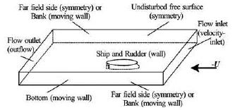
Fig.1 Computational domain and boundaries
The computational domain and the hull-rudder system are regarded as stationary, while an inflow of velocityU- is imposed to the hull-rudder system, whereUis the ship speed in the longitudinal direction. As is referred to boundaries shown in Fig.1, the boundary conditions are set as follows[12-15]:
(1) Inlet: The inlet boundary is 1.0Lahead of the bow, whereLis the ship length, and a velocity-inlet condition is imposed on it, the inflow velocity isU-, with turbulence intensityIand hydraulic diameterDHused to set the turbulence.
(2) Outlet: The outlet boundary is 3.0Ldownstream of the stern. As the flow there is considered to be fully developed, an outflow condition is imposed on it.
(3) Hull and rudder surfaces: On the hull and rudder surfaces, no-slip wall condition is imposed.
(4) Free surface: Under the assumption of low ship speed, the influence of free surface elevation on the hydrodynamic force is negligible, thus the undisturbed free surface is treated as symmetrical plane and a symmetry condition is imposed on it.
(5) Bank and bottom: According to the principle of relative motion, the banks and bottom are moving with velocityU-, thus no-slip moving wall condition is imposed on them.
(6) Far field side: For the cases of transversely unbounded flow field, the far field side is 1.5Laway from the hull-rudder system. Since the disturbance induced by the hull-rudder system is weak on these boundaries, a symmetry condition is imposed on them.
1.3Numerical method
The Finite Volume Method (FVM) was used to discretize the governing equations. The pressure equation was discretized by a second-order central difference scheme, while the momentum equations and turbulence equations were discretized by a second-order upstream scheme to guarantee the calculation accuracy. The SIMPLEC algorithm was applied to solve the velocity-pressure coupling problem.
In this paper, hybrid unstructured mesh with multi-blocks was utilized. The block containing the rudderwas mainly meshed with tetra elements, and the other blocks were meshed with hex elements. Askε- turbulence model with standard wall function treatment was adopted in the calculation,+yat the wall surface should be limited in the range of 30-300, and prism elements were used in the tetra meshed block to achieve this. Meanwhile, finer mesh was used around the bow and stern.
2. Validation of the numerical method
Validations were carried out separately for both the numerical predictions of bank effect and rudder effect. For validation of bank effect prediction, an 8 000 TEU container ship model towed along a sloping bank in the Towing Tank for Manoeuvres in Shallow Water at FHR[16]in Belgium was chosen as the study object. For validation of rudder effect prediction, rudder force tests of a KVLCC1 model carried out by NMRI[17]in Japan were chosen as the study object.
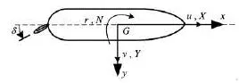
Fig.2 Coordinate system
The right-handed coordinate system adopted in this paper is shown in Fig.2, with theyaxis pointing to the starboard of the ship and thez-axis pointing down to the bottom. In the figure,X,YandNare respectively the components of the hydrodynamic force and moment acting on the ship, andδis the rudder angle.
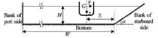
Fig.3 Sketch for a ship towed along a sloping bank in shallow water
2.1Validation of bank effect prediction
The 8 000 TEU container carrier towed along a sloping bank in shallow water is shown in Fig.3. The ship model is equipped with a rudder and the rudder angle remains 0 in accordance with the model test. The influence of propeller is neglected in the numerical study, whereas the revolution rate of propeller is 0 in the model test. The principal parameters for the validation study are given in Table 1.
In order to compare with the experimental data, distance to bank (d2b) defined by Lataire et al.[16]was used for expressing the ship to bank distance
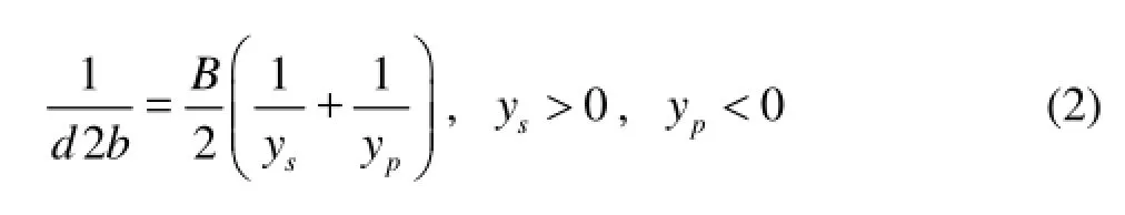
where -ypis defined as twice the distance between the ship’s longitudinal central plane and the lateral position of the center of the cross section of the channel at port side; and the distance to the bank at the starboard side (ys) is defined in a similar way[16]. We have
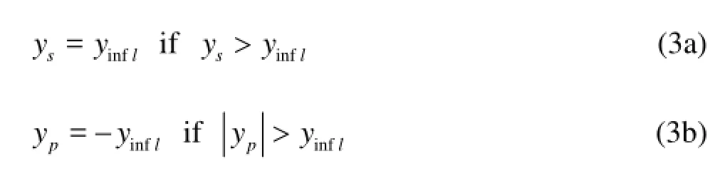
whereinflyis defined as the function of the Froude depth numberhFr

The test conditions for numerical simulation are given in Table 2.
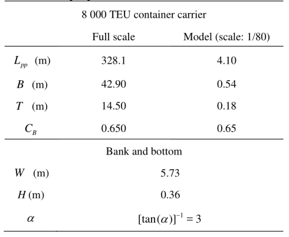
Table 1 Principal parameters for validation of bank effect

Table 2 Test conditions for validation
In the calculation, the iteration process was continued until the proper convergence for the forces had been achieved. In the present study, numerical error due to iteration is less than 0.1%.
The calculated sway force is compared with test data for validation, as shown in Fig.4.
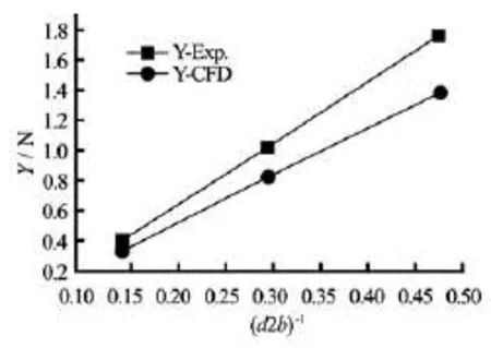
Fig.4 Hydrodynamic force changing with ship-bank distance
It can be seen from this figure that the calculated hydrodynamic force is smaller than that from the test with an average error of 19%. However, the trend of the calculated hydrodynamic force changing with the ship-bank distance agrees well with the test data.
2.2Validation of rudder effect prediction
The principal particulars of the KVLCC1 are listed in Table 3. Calculations were conducted for the hull-rudder sy6stem at the speed 0.76 m/s (Fr=0.412,Re=2.2×10) and rudder angle varied within the range of –20o-20o, with 5oas the interval.
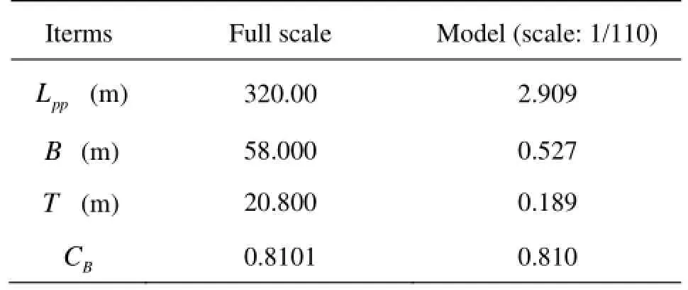
Table 3 Principal particulars of the KVLCC1
The comparison of calculated hydrodynamic forces and moment with the test data is shown in Fig.5, whereY′ versusFN′ cosδin 5(c) andN′ versusFN′ cosδin 5(d) are used to illustrate the feature of hydrodynamic interaction between the hull and rudder.FNis the normal component of the hydrodynamic force acting on the rudder.Y′,FN′ andN′ are respectively the non-dimensional hydrodynamic forces and moment. It can be seen from Figs.5(a) and 5(b) that the discrepancy between the calculated results and those from model test are not small. Qualitatively, however, agreement has been achieved in regard of the feature of hydrodynamic interaction between the hull and rudder, as shown in Figs.5(c) and 5(d). Thus the present numerical method can be used to predict the hull-rudder hydrodynamic features properly to some extent.

Fig.5 Validation for the prediction of rudder effect
3. Numerical results and discussion
3.1Study object
The container ship KCS appended with a rudder towed along a vertical bank in shallow water was taken as the study object. The profiles of the hull andrudder are shown in Fig.6 and the principal parameters for the numerical study are listed in Table 4[17]. The scale was chosen as 1:45 to achieve properhFrandRewhich are similar to the calculation conditions in the validation process.

Fig.6 Profiles of the KCS hull and rudder
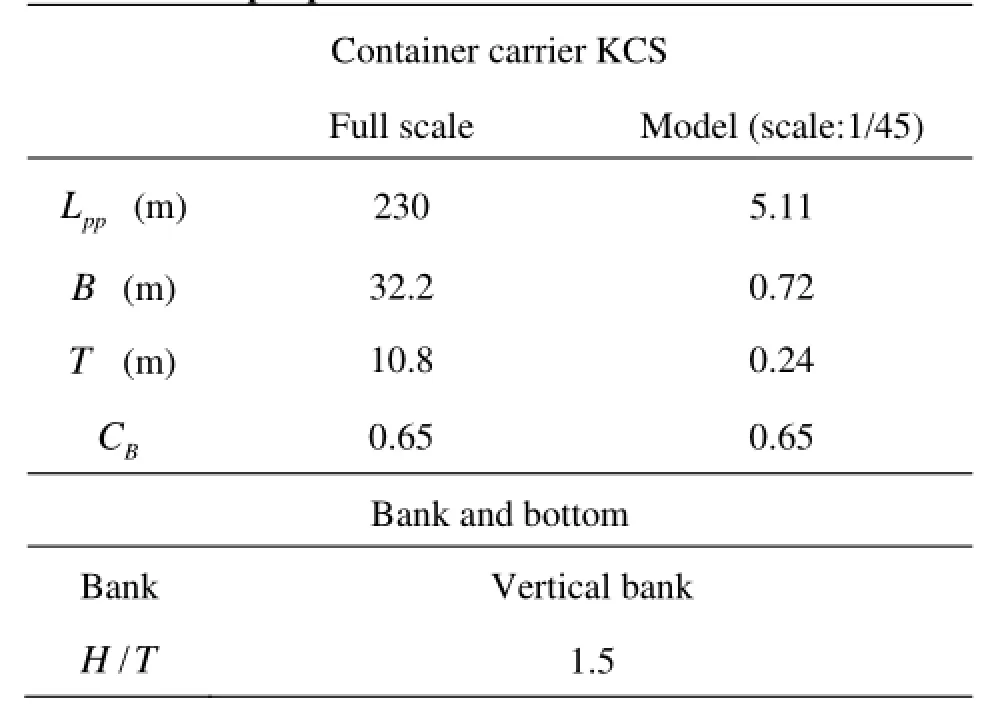
Table 4 Principal parameters of the KCS hull and bank
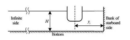
Fig. 7 Study object of hydrodynamic interaction
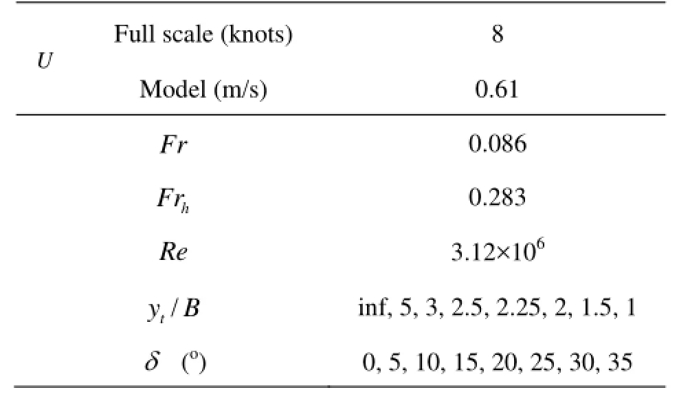
Table 5 Calculation conditions
The influences of ship squat, free surface elevation and propeller out-stream were neglected in the numerical calculation. The calculation conditions are shown in Fig.7 and Table 5, whereyt/B=inf means that there exists no bank.
Three kinds of calculation models are taken into consideration in order to study the hydrodynamic interaction: (1) HRB, which includes the hull, rudder and a starboard side bank, bothδandtyvary in the study, (2) HR, which only includes the hull and rudder, no banks exist, and onlyδvaries, (3) HB, which includes the hull, rudder and a starboard side bank,tyvaries, while =δ0.
3.2Bank effect
The HB model is used to illustrate the bank effect. Figure 8 shows the calculated hydrodynamic force and moment acting on the ship for the HB model. Obvious bank effect can be observed in Fig.8. As the ship-bank distance is getting smaller, the hydrodynamic force pointing to the bank becomes larger and increases rapidly whenyt/Bis small, and the hydrodynamic moment pushing the stern towards the bank changes in the similar way.
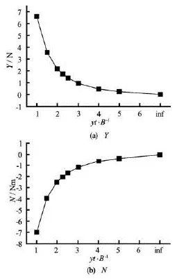
Fig.8 Calculated hydrodynamic force and moment changing with ship-bank distance
Figures 9 and 10 depict respectively the velocity distribution on the undisturbed free surface and the pressure distribution on the ship for the case ofyt/B=2.25 andδ=0. These figures with flow field features can partially explain the phenomena of bank effect: The velocity near the starboard bank side is larger than that near the port bank side, thus the pre-ssure on the ship in the starboard side is smaller according to the Bernoulli equation, and this asymmetrical pressure distribution on ship results in the hydrodynamic force pointing to the bank. 3.3Rudder effect
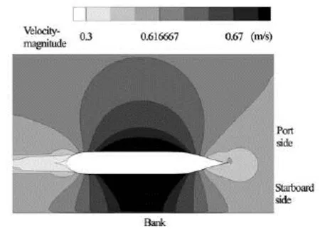
Fig.9 Velocity-magnitude on the undisturbed free surface (yt/B=2.25,δ=0)
Fig.10 Pressure distribution on the ship (yt/B=2.25,δ=0)
Figure 11 shows the calculated hydrodynamic force and moment acting on the ship at different shipbank distances and rudder angles. It can be seen that if the ship sails not too close to the bank, the sway force changes from positive (suction force) to negative (repulsive force) and the yaw moment changes from negative (stern suction) to positive (bow suction) with the increase of rudder angle. That means, with the increase of rudder angle, the control effect generated by the rudder indeed helps to reduce the bank effect. However, if the ship sails very close to the bank, the sway force will remain positive and yaw moment will remain negative, which means that the control effect generated by the rudder is not sufficient to balance the bank effect.
Figures 12 and 13 show respectively the pressure distributions on the rudder and on the ship for the case of /=yB2.25 and =δ35o. The rudder’s control effect to balance the bank effect can be explained according to these figures. Firstly, the pressure on the sta-trboard side of the rudder is much larger than that on the port side, as shown in Fig.12, as a result, a control force pointing to the port side is induced. Secondly, comparing Fig.13 with Fig.10 we can see that the rudder angle makes the pressure distribution on the hull more symmetric about the longitudinal central plane of the ship, as a result, the sway force on the hull is reduced.
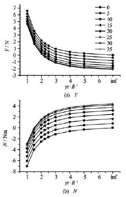
Fig.11 Calculated hydrodynamic force and moment changing with ship-bank distance at different rudder angles
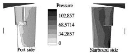
Fig.12 Pressure distribution on the rudder (yt/B=2.25,δ= 35o)
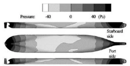
Fig.13 Pressure distribution on the ship (yt/B=2.25,δ=35o)
3.4Hydrodynamic interaction among hull, rudder and bank
It can be seen from Fig.11 that the curves for the hydrodynamic force and moment at different rudder angles are not parallel to each other, which indicates that there exits hydrodynamic interaction among the hull, rudder and bank. In order to study this hydrodynamic interaction, the quantities ΔYand ΔNare proposed in this paper. Denoting the hydrodynamic forceYand momentNacting on the hull-rudder system in the three calculation models asYHRB,YHR,YHBandNHRB,NHR,NHB, respectively, for a certain set ofytandδ, ΔYand ΔNcan be defined as follows:
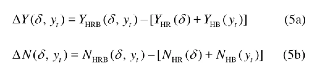
The larger the absolute ΔYor ΔN, the greater the hydrodynamic interaction; and the sign of ΔYand ΔNcan indicate the effect of this hydrodynamic interaction.

Fig.14 Analysis of hydrodynamic interaction under different calculation conditions
ΔYand ΔNfor the calculation conditions in Table 5 are obtained and shown in Fig.14 for different ship-bank distances and rudder angles. It can be seen that the absolute values of ΔYand ΔNare small, when the rudder angle is not very large or when the ship sails not very close to the bank. This indicates that in these situations the influence of hydrodynamic interaction on ship manoeuvring and control is small and can even be neglected, thus the whole hydrodynamic forceYHRB(or momentNHRB) can be predicted approximately byYHR+YHB(orNHR+NHB). In this way, we can adopt the HR model and HB model instead of the HRB model, which makes the prediction more convenient and simpler.
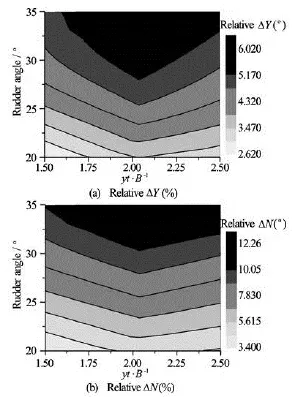
Fig.15 Contours of relativeYΔ andNΔ
However, when the ship is sailing very close to the bank with a large rudder angle, the hydrodynamic interaction is stronger. SinceYΔ is positive andNΔ is negative in this situation, as shown in Fig.14, this hydrodynamic interaction may weaken the control effect of rudder. In order to estimate the significance of this interaction, the relative hydrodynamic forceYΔ and the relative momentNΔ are introduced here: Obviously, the larger the relative ΔY(relative ΔN), the more significant this hydrodynamic interaction compared with the bank effect itself. ΔYand ΔNare calculated and shown in Fig.15 for the cases in which the ship is sailing very close to the bank with a large rudder angle. The largest ΔYrelitiveis 6.02% and the largest ΔNrelitiveis 12.26%, which indicates thatthe hydrodynamic interaction might be significant to some extent and should be taken into consideration for more accurate prediction of ship manoeuvring motion. It can also be seen that the significance of hydrodynamic interaction will increase with the increase of rudder angle, but may not monotonously change with the ship-bank distance.
4. Conclusions
By using CFD method to solve the RANS equations, the viscous flow around a hull-rudder system towed along a bank in shallow water has been numerically simulated and the hydrodynamic interaction among the hull, rudder and bank has been studied. From this numerical study, the following conclusions can be drawn:
(1) By comparing the calculated hydrodynamic force and moment with the test data, it can be seen that although there do exist discrepancies between them, the numerical results can reveal the characteristics of hull-rudder and ship-bank hydrodynamic interactions properly to some extent, which means the present numerical method is effective to study the hull-rudder-bank hydrodynamic interaction.
(2) The bank effect for a ship sailing along a bank can be predicted by the numerical method. This effect can be partially explained by the asymmetric flow around the ship.
(3) The rudder’s control effect can help to counteract the bank effect and this can be explained by the asymmetric pressure distribution on the rudder and the more symmetrical pressure distribution on the hull.
(4) The hydrodynamic interaction among the hull, rudder and bank is studied by carrying out simulation at different ship-bank distances and rudder angles, and ΔY(ΔN) is introduced to estimate the significance of this hydrodynamic interaction. For ships sailing not very close to the bank or with not very large rudder angle, the hydrodynamic interaction is weak, thus the hydrodynamic force and moment of HRB model can be predicted properly by the HB model and HR model. For ships sailing close to the bank with large rudder angle, the hydrodynamic interaction might be relatively significant as estimated by the relative quantities ΔYand ΔN.
In order to analyze the hydrodynamic interaction more accurately, future study may focus on further analysis of the errors induced by modeling assumption or numerical solving process.
Acknowledgement
The authors would like to express their sincere thanks to the Knowledge Centre Manoeuvring in Shallow and Confined Waters at Flanders Hydraulics Research and Ghent University for providing the model test data.
[1] LO D. C., SU D. T. and CHEN J. M. Application of computational fluid dynamics simulations to the analysis of bank effects in restricted waters[J].Journal of Navigation,2009, 62(3): 477-491.
[2] WANG H., ZOU Z. and XIE Y. et al. Numerical study of viscous hydrodynamic forces on a ship navigating near bank in shallow water[C].Proceedings of the 20th International Offshore and Polar Engineering Conference, ISOPE2010.Beijing, China, 2010, 523-528.
[3] ZOU L., LARSSON L. Computational fluid dynamics (CFD) prediction of bank effects including verification and validation[J].Journal of Marine Science and Technology,2013, 18(3): 310-323.
[4] SIMONSEN C. D., STERN F. Verification and validation of RANS manoeuvring simulation of Esso Osaka: Effects of drift and rudder angle on forces and moments[J].Computers and Fluids.2003, 32(10): 1325-1356.
[5] SIMONSEN C. D., STERN F. Flow pattern around an appended tanker hull form in simple manoeuvring conditions[J].Computers and Fluids,2005, 34(2): 169-198.
[6] CARRICA P. M., HAMID S. H. and STERN F. CFD analysis of broaching for a model surface combatant with explicit simulation of moving rudders and rotating propellers[J].Computers and Fluids,2012, 53: 117-132.
[7] HAMID S. H., CARRICA P. M. and STERN F. et al. CFD, system-based and EFD study of ship dynamic instability events: Surf-riding, periodic motion, and broaching[J].Ocean Engineering,2011, 38(1): 88-110.
[8] ELOOT K., VERWILLIGEN J. and VANTORRE M. A methodology for evaluating the controllability of a ship navigating in a restricted channel[J].Archives of Civil and Mechanical Engineering,2007, 7(3): 91-104.
[9] ZHOU M., MA S. and ZOU Z. CFD-based hydrodynamic analysis for a ship sailing along a bank in restricted waters[J].Transactions of the Royal Institution of Naval Architects, Part A: International Journal of Maritime Engineering,2013, 155(Part A2): 49-58.
[10] FERZIGER J. H., PERIC M.Computational methods for fluid dynamics[M]. 3rd Edition, New York, USA: Springer-Verlag, 1996.
[11] VERSTEEG H. K., MALALASEKERA W.An Introduction to computational fluid dynamics: The finite volume method[M]. Essex, UK: Longman Group Limited, 1995.
[12] WANG Hua-ming, ZOU Zao-jian and TIAN Xi-min. Numerical simulation of transient flow around a ship in unsteady berthing motion[J].Journal of Hydrodynamics,2009, 21(3): 379-385.
[13] LI Dong-li. Computation of hydrodynamic derivatives related to ship maneuverability in viscous flows[J].Journal of Harbin Engineering University,2010, 31(4): 421-427(in Chinese).
[14] TIAN Xi-min, ZOU Zao-jian and WANG Hua-ming. Computation of the viscous flow and hydrodynamic forces on a KVLCC2 model in oblique motion[J].Journal of Ship Mechanics,2010, 14(8): 834-840(in Chinese).
[15] YANG Yong, ZOU Zao-jian and ZHANG Chen-xi. Calculation of hydrodynamic forces on a KVLCC hull in sway motion in deep and shallow water[J].Chinese Journal of Hydrodynamics,2011, 26(1): 85-93(in Chinese).
[16] LATAIRE E., VANTORRE M. and ELOOT K. Systematic model tests on ship-bank interaction effects[C].Proceedings of International Conference on Ship Manoeuvring in Shallow and Confined Water: Bank Effects.Antwerp, Belgium, 2009, 9-22.
[17] STERN F., AGDRUP K. and KIM S. Y. et al. Experience from SIMMAN 2008-the first workshop on verification and validation of ship maneuvering simulation methods[J].Journal of Ship Research,2011, 55(2): 135-147.
10.1016/S1001-6058(13)60428-X
* Project supported by the National Natural Science Foundation of China (Grant No. 51061130548).
Biography: MA Shao-jun (1988-), Male, Ph. D. Candidate
ZOU Zao-jian,
E-mail: zjzou@sjtu.edu.cn

- 水动力学研究与进展 B辑的其它文章
- A three-dimensional hydroelasticity theory for ship structures in acoustic field of shallow sea*
- Experimental study of the interaction between the spark-induced cavitation bubble and the air bubble*
- A preliminary study of the turbulence features of the tidal bore in the Qiantang River, China*
- The calculation of mechanical energy loss for incompressible steady pipe flow of homogeneous fluid*
- Experimental study by PIV of swirling flow induced by trapezoid-winglets*
- Analysis of shear rate effects on drag reduction in turbulent channel flow with superhydrophobic wall*