High Temperature Corrosion of Water Wall Materials T23 and T24 in Simulated Furnace Atmospheres*
ZHAO Qinxin (赵钦新), ZHANG Zhixiang (张知翔)**, CHENG Dingnan (成丁南),WANG Yungang (王云刚) and DENG Xiang (邓翔)
1 Key Laboratory of Thermo-Fluid Science and Engineering of Ministry of Education, Xi’an Jiaotong University,Xi’an 710049, China
2 Xi’an Thermal Power Research Institute Co., Ltd., Xi’an 710032, China
1 INTRODUCTION
With the application of supercritical and ultrasupercritical utility boilers, the pressure and temperature of steam will be continuously increased. At present, the temperature of the water wall reaches 560 °C.In the future, the stream temperature may be as high as 700 °C, and the temperature of the water wall will be higher accordingly. Table 1 [1] gives the types and chemical compositions of candidate materials of the water wall. Many experiments have proved that, with an increase in the content of chrome and other alloy elements, the working temperature of the heat-resistant materials can be increased in the order of 480 °C→530 °C→560 °C→580 °C→625 °C, accomplishing the transition from supercritical materials to ultra-supercritical materials.
With environmental issues becoming more and more prominent, low-NOxburners have been widely applied, resulting in a further decrease in the excess air ratio and the reducing atmosphere in the furnace. Moreover, in large capacity units, because the aerodynamic field is irregular and the combustion atmosphere is more complex, besides oxidizing atmosphere and reducingatmosphere, another atmosphere, oxidizing/reducing alternating atmosphere, appears. The metal parts will suffer more severe corrosion when they are exposed to high temperatures and the oxidizing/reducing alternating atmosphere. While the high-temperature corrosion has been studied by a large number of scholars [2-10],there are fewer reports on high-temperature corrosion in reducing atmosphere and alternating atmosphere.

Table 1 Chemical composition of candidate materials of water wall
Niuet al. investigated the corrosion behavior of 12Cr steel in the oxidizing/vulcanizing alternating atmosphere [11]. Cenet al. reviewed the results of H2S corrosion, without mentioning the corrosion in the alternating atmosphere [12]. Tmisitaet al. conducted measurements in an experimental boiler and illustrated that high-temperature corrosion is more severe with H2S present, and investigated the influence of H2S concentration and oxygen content on corrosion in the reducing atmosphere [13]. Other researches also involved the corrosion of metals by H2S [14, 15]. The corrosion behavior of carbon steel in the oxidizing atmosphere and the reducing atmosphere was investigated using thermodynamics [16, 17]. However, scholars only agree qualitatively with each other about the results of high-temperature corrosion of H2S. Few studies have been conducted on the alternating atmosphere and candidate supercritical and ultra-supercritical materials.
In this study, candidate materials T23 and T24 for the water wall of supercritical and ultra-supercritical utility boilers are chosen as the experimental samples.Under laboratory conditions, the furnace atmosphere is simulated as oxidizing atmosphere, reducing atmosphere, and oxidizing/reducing alternating atmosphere separately. The corrosion temperature is 450-550 °C.The scanning electron microscope (SEM) and energy dispersive spectrometer (EDS) are used to analyze the surface and the migration of alloy elements in the cross section of the samples, respectively. The failure mechanism of high-temperature corrosion and the anti-corrosion mechanism of the water wall materials are analyzed based on the migration of alloy elements.
2 EXPERIMENTAL
The experimental system is shown in Fig. 1.Different gases from gas cylinders and through mass flow controllers were mixed sufficiently in the gas mixing vessel. The total flow rate was 100 ml·min-1.The test samples were placed in the high-temperature tube furnace, which provides an unchanged corrosion temperature of 450 °C with an accuracy of ±1 °C. The exhaust gas was absorbed by NaOH solution.
In an actual boiler, the atmosphere in the burner,which is extremely complex, can be basically classified to oxidizing atmosphere, reducing atmosphere, and oxidizing/reducing alternating atmosphere. Table 2 shows the content of gases in different atmosphere. The alternating atmosphere features alternative changes between oxidizing atmosphere and reducing atmosphere.

Table 2 Content of gases in different atmosphere
The test samples were cut as 8 mm×8 mm×3 mm,grinded by sandpaper with the grit size up to 1200,degreased with acetone, washed with de-ionized water and then dried by a hairdryer. Table 3 shows the chemical compositions of the experimental materials.
In the test, the weighing sampling points were 2,4, 6, 8, 24, 48, 96, and 196 h. In each sampling interval in the alternating atmosphere, the oxidizing atmosphere and the reducing atmosphere occur once each. In the early stage of the test, the difference in the corrosion mass gain of the same material was obvious, so the average value of parallel samples was used. With an increase in corrosion time, the difference of corrosion mass gain decreased, allowing the average value of fewer samples to fulfill the demand for accuracy. Eight samples were used for each material in the test. At the first sampling point, the mass gain was the average value of the eight samples, and then one of the samples was taken out for further analysis. At the second sampling point, the mass gain was the average value of the remaining seven samples, and another sample was taken out for further analysis. The procedure continued until only one sample was left for the last sampling point.
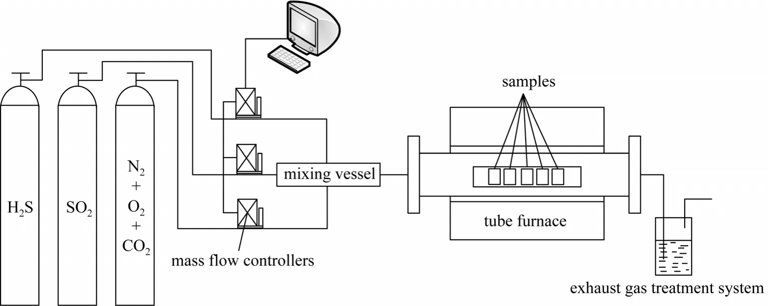
Figure 1 The experimental system

Table 3 Chemical composition of experimental materials
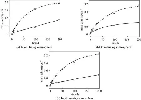
Figure 2 Corrosion kinetics of two materialsT23; T24
The following measurements were performed to analyze the corroded samples.
(1) Mass measurement: the mass of each sample before and after corrosion was measured by a microgram balance (with a resolution of 10-6g), and then the corrosion kinetics of each material was obtained.
(2) Corrosion thickness measurement: SEM was used to examine the thickness of the corroded layer in each sample.
(3) Migration depth measurement: EDS was used to analyze the distribution of corrosive elements of each corroded sample to measure the migration depth of sulfur and oxygen.
3 RESULTS AND DISCUSSION
3.1 Corrosion kinetics and corrosion equations of materials
Figure 2 shows the mass gain of two materials after exposed for 196 h to three different atmospheres.The corrosion resistance of T23 was almost twice of that of T24. The corrosion layer of T23 was brittle and easy to spall, while the corrosion layer of T24 was more compact.
Five equations were applied for the corrosion kinetics of the two materials in different atmospheres.The equation with the smallest fitting error is the most appropriate one to describe the corrosion of material.The five fitting equations are: parabolic equationy2=a+bt, logarithmic equationy=k1lnt+k2, hyperbolic equationy-1=a+b-1, double logarithmic equation lgy=a+blgt, and anti-logarithmic equationy-1=a+blgt. The fitting result is shown in Table 4.
3.2 Effect of atmosphere
Figure 3 shows the morphology of T24 samples with 196 h of corrosion in three atmospheres. The surfaces of all samples are covered by a thin layer of Fe2O3and the size of Fe2O3flake increases with oxygen content. Therefore, the Fe2O3flakes are the largestin size in the oxidizing atmosphere and the smallest in the reducing atmosphere.

Table 4 Corrosion kinetics of two materials in different atmospheres (t/h, y/mg·cm-2)

Figure 3 SEM images of corrosion T24 samples

Figure 4 Corrosion layer, pitting corrosion, and content of elements in corrosion layer of T24 with 196 h exposure in oxidizing atmosphere
3.3 The composition of corrosion products
Figure 4 (a) shows the corrosion layer of T24 with 196 h exposure in the oxidizing atmosphere.There are several layers in the corrosion layer. By XRD, mixture of Fe2O3, Fe3O4and Fe are found in the corrosion layer. Combined with the description in [12],it can be said that the outer layer is the columnar and loose Fe2O3layer, and the inner layer is the dense Fe3O4layer. With the point spectrum scanning applied to the corrosion layer, Fig. 4 (c) shows the content of each element in the corrosion layer. The content of oxygen is very high, about 30%, in the corrosion layer,but there is little oxygen in the metal matrix. Sulfur can be found in the outer layer only. The chrome content is very low in the outer layer but very high in the inner layer, which is almost three times that in the matrix. The enrichment of chrome extends to the matrix and is able to effectively protect the metal from corrosion. The content of each element from corrosion layer to matrix is shown in Table 5. Fig. 4 (b) shows that the corrosion starts with the formation of point corrosion,and the point spectrum scanning image shows that oxygen and sulfur are present in the grain boundary.

Table 5 Content of element from corrosion layer to matrix of T24 in oxidizing atmosphere
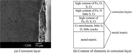
Figure 5 Corrosion layer and content of elements in corrosion layer of T24 with 196 h exposure in reducing atmosphere

Figure 6 Corrosion layer and content of elements in corrosion layer of T24 with 196 h exposure in alternating atmosphere
Figure 5 (a) shows the corrosion layer of T24 with 196 h exposure in the reducing atmosphere.There are three layers in the corrosion layer. The outer and inner layers are compact, and the intermediate layer is the columnar and loose Fe2O3layer. Fig. 5 (b)shows the content of each element in the corrosion layer. The contents of oxygen, sulfur, and chrome in the outer and inner layers are very high, so the compositions of the corrosion products in these two layers are FeS, Fe3O4, and Cr2O3. The contents of sulfur and chrome in the intermediate layer are comparably low,and the corrosion products are FeS and Fe2O3. Table 6 shows the content of elements in each layer. With the matrix layer, chrome is enriched, and a little oxygen and sulfur can be found as well. The point spectrum scanning image shows some cracks in the matrix andsevere corrosion in the vicinity of cracks. In the deeper parts of the matrix, a spot of sulfur instead of oxygen can be found. The distribution of sulfur and oxygen shows that sulfur, which is extra-ordinarily active, can penetrate through the dense protective layers, such as the Fe3O4layer and the Cr2O3layer.
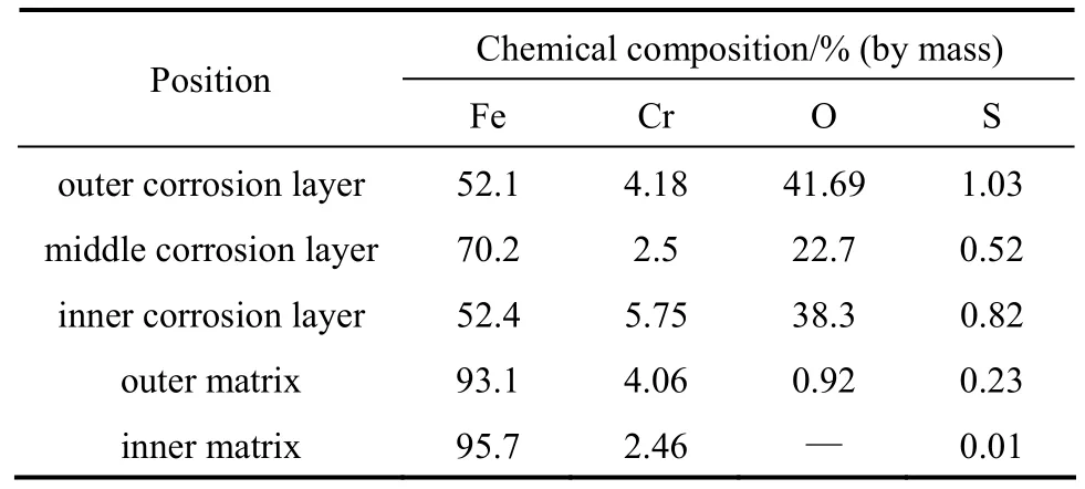
Table 6 Content of element from corrosion layer to matrix of T24 in reducing atmosphere
Figure 6 shows the corrosion layer and its element content of T24 with 196 h exposure in the alternating atmosphere. The corrosion layer is much thicker than that in the oxidizing atmosphere. Table 7 shows the content of each element from corrosion layer to matrix,with very high content of oxygen in the entire corrosion layer, reaching more than 40%. The content of sulfur has an obvious difference in different layers, and reaches its maximum in the inner layer and the minimum in the outer layer. In the forefront of the corrosion layer, a spot of sulfur and oxygen can be found,indicating that sulfur and oxygen can migrate to the matrix in the corrosion, and cracks also appear in the vicinity of the forefront layer. An enrichment of chrome is found in the inner corrosion layer and in the matrix adjacent to the corrosion layer.
Figure 7 shows the thickness of the corrosion layer of T24 with 196 h exposure in the three atmospheres. The thickness of corrosion layer varies in different atmospheres, and is the maximum in the alternating atmosphere and the minimum in the oxidizingatmosphere. The migration of sulfur and oxygen to the matrix only appears in the reducing atmosphere and the alternating atmosphere, indicating that sulfur is more active than oxygen in the corrosion. Furthermore,the migration in the alternating atmosphere is more obvious than that in the reducing atmosphere.
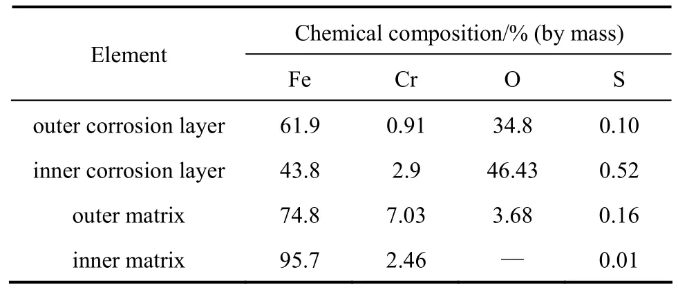
Table 7 Content of element from corrosion layer to matrix of T24 in reducing atmosphere
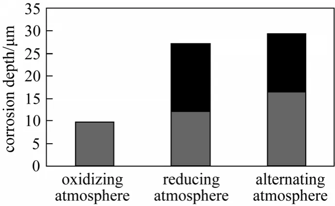
Figure 7 Migration depth of corrosion elements of T24 in three atmospheres■ migration depth;corrosion layer depth
As shown in Fig. 2, there is no obvious difference in the mass gain of a certain metal element in the three atmospheres. And as shown in Fig. 7, the difference in the thickness of corrosion layer in the three atmospheres is not obvious either, which does not coincide with the actual situation. In reality, the atmosphere with H2S is much more dangerous than that without H2S. However, from the migration depth of corrosive elements, the difference is obvious, which agrees well with the actual situation. Therefore, to describe the corrosion of metal elements accurately, it is not sufficient to just analyze the mass gain of samples and the thickness of corrosion layer. The migration depth of corrosive elements (oxygen and sulfur)must be examined.
From the above study on the corrosion layer,some conclusions can be reached. The content of oxygen in the corrosion layer in the three atmospheres is always very high, indicating that oxygen is the key factor for the mass gain. For the Cr-rich layer present in each of the corroded samples, oxygen can not penetrate it, but sulfur can penetrate and migrate to deeper part of the matrix. In the oxidizing atmosphere, little grain boundary crack appears in the corrosion layer and oxygen can not be found in the matrix. However,once the samples are exposed to the atmosphere containing H2S, grain boundary cracks form and oxygen can migrate to the matrix. The grain boundary corrosion is caused by H2S and grain boundary cracks help the migration of oxygen and sulfur. If oxygen moves along the migration route of sulfur and migrates to the matrix, the corrosion in the forefront of the corrosion layer should be caused only by sulfur.
Figure 8 shows the corrosion depth of T24 with of 24 h exposure in the reducing atmosphere. The content of oxygen in the corrosive gas plays an important role in corrosion depth. When the percentage of oxygen is within 0-0.5%, the corrosion depth is almost unchanged and the corrosion rate is the lowest,between 0.2%-0.5%. The corrosion depth increases quickly when the content of oxygen increases to 0.8%-1.0%. A layer of sulfur appears in the inner surface of the high-temperature tube furnace at the same time, indicating that with an increase in the partial pressure of oxygen, the sulfur layer will react with H2S and produce sulfur steam more readily, which causes severe corrosion. This also indicates that the corrosion ability of sulfur steam is stronger than H2S.The corrosion rate decreases from 0.8% to 1.0%,mainly because high oxygen content will oxidize sulfur to SO2. Without oxygen in the corrosive gas, CO2acts as an oxidant on the corrosive sample, so oxygen can still be found in the corroded samples.

Figure 8 The change of corrosion depth with oxygen content
Figure 9 shows the corrosion depth when the corrosion temperature changes in 450-550 °C. The control of the temperature of water wall is necessary.

Figure 9 The change of corrosion depth with temperature
3.4 Mechanism of high-temperature corrosion
The corrosion layer of materials (as shown in Fig. 5)consists of a loose outer Fe2O3layer and a compact inner Fe3O4layer (a mixture of Fe2O3and FeO). When the corrosive gas contains H2S, it destroys the oxide layer and penetrates through the Fe2O3layer to the Fe3O4layer and reacts with FeO [11]:

S2-remains in the reducing atmosphere since it has strong reducibility. When the oxygen content increases to a certain value, S2-is oxidized to sulfur or SO2

Some of the sulfur produced by reactions (4) and(5) migrates to the matrix and the remaining migrates to the side near the surface. Sulfur then reacts with Fe

Therefore, when the oxygen content is lower than a certain value, H2S, as a main corrosive agent, penetrates through the corrosion products to the metal matrix and reacts with Fe to produce FeS. When the oxygen content is higher than a certain value, oxygen,as the main corrosive agent, migrates to the corrosion layer and reacts with FeS to produce FeO and sulfur[18]. Thus it is difficult for oxygen to migrate to the corrosion forefront. Nevertheless, it is easy for sulfur to migrate to the forefront of the corrosion layer. In this way, there is an enrichment of sulfur in the inner part of the corrosion layer and low sulfur content in the outer layer [as shown in Figs. 5 (c) and 6 (b)].Sulfur is able to migrate to the inner part of the matrix along the grain boundary and causes grain boundary corrosion, which helps the deep migration of oxygen.This is why a spot of oxygen and sulfur is found in the part of the matrix close to the corrosion layer, while only sulfur is found in the inner part far away from the corrosion layer.
3.5 Effect of materials

Figure 10 Surface SEM images ofT23 andT24 in the alternating atmosphere

Figure 11 Corrosion layer of T23 and T24 in alternating atmosphere
Corrosion of the two materials in the alternating atmosphere was analyzed. Fig. 10 shows the surface SEM image of two materials with 196 h exposure.Because the corrosion surface of T24 is loose in structure, the corrosive gases can easily penetrate through the surface and corrode the lower layers, leading to obvious mass gain. In contrast, the compact corrosion surface of T23 can protect the lower layers from further corrosion.
3.6 Analysis on chemical compositions of corrosion
Figure 11 shows the corrosion layer of two materials with 100 h exposure in the alternating atmosphere. The corrosion layers are all laminar in structure but different in thickness. The corrosion of T23 seems to be in the form of grain boundary corrosion, but in its matrix, oxygen and sulfur can only be found in the part near the corrosion layer. In the part far away,wolfram and chrome precipitate, preventing further corrosion. The corrosion of T24 changes the structure of its matrix part, in which the enrichment of chrome and a spot of sulfur and oxygen appear.
Figure 12 shows the corrosion depth of two materials with 100 h exposure in the alternating atmosphere. The corrosion resistance of T23 is almost twice that of T24, consistent with the mass-gain experiment.
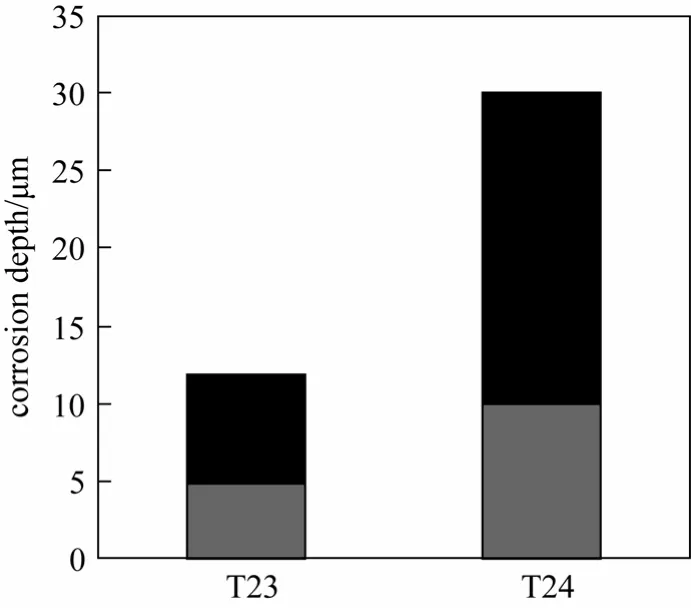
Figure 12 Corrosion depth of materials in alternating atmosphere■ migration depth;corrosion layer depth
The comparison of matrix elements of T23 and T24 shows that there is wolfram and boron in T23. Fig.13 shows the mechanism of corrosion resistance of T23. Fig. 13 (a) shows the elemental distribution in corroded T23. EDS shows that the content of wolfram and chrome in the corrosion layer reaches 11.46% and 8.53% respectively, much higher than their contents in the matrix. Furthermore, the part of the corrosion layer expected to exhibit an enrichment of sulfur [Fig. 6 (b)]has a low content of sulfur, which is believed to be the effect of wolfram and chrome enrichment. Moreover,as shown in Fig. 13 (b), the precipitation in the grain boundary, which contains 11.46% wolfram and 8.53%chrome, is also able to prevent corrosion. However,because the content of B in T23 is very low, it is difficult to detect the enrichment of wolfram in the grain boundary. Compared with T24, T23 has better corrosion resistance and can be satisfactorily utilized in reducing corrosive environment and alternating corrosive environment.

Figure 13 Mechanism of corrosion resistance of T23
4 CONCLUSIONS
High-temperature corrosion of candidate materials T23 and T24 for the water wall of supercritical and ultra-supercritical utility boilers were examined in oxidizing atmosphere, reducing atmosphere and oxidizing/reducing alternating atmosphere separately. These conclusions are derived from the experimental results.
(1) The surface of the corroded samples in the three atmospheres consists of a thin sheet of Fe2O3,and the size of Fe2O3flakes increases with oxygen content in the corrosive gas. The surface of T24 is a compact layer, while that of T23 is a loose one.
(2) The corrosion of T24 in the three atmospheres shows that the outer layer is columnar and loose, while the inner layer is compact. An enrichment of chrome appears in part of the inner corrosion layer, which can inhibit the migration of oxygen but not sulfur. The forefront of corrosion is caused by sulfur only.
(3) To accurately describe the corrosion of materials, mass gain, thickness of corrosion layer and depth of migration of corrosive elements (oxygen and sulfur) should be all considered.
(4) Corrosion becomes more severe when H2S is present in the corrosive gas. The combination of oxygen and sulfur has a stronger corrodibility than pure H2S. Thus, the most severe corrosion appears in the alternating atmosphere.
(5) Sulfur has a stronger corrodibility than pure H2S, and T24 suffers the most severe corrosion under the condition with 0.8% oxygen content.
(6) When the temperature is above 450 °C in the alternating atmosphere, the thickness of corrosion layer increases with temperature.
1 Zhao, Q., Zhu, L., Study of Heat-resistant Steel for Super-critical Boiler, Machine-building Industry Press, Beijing, 334 (2009). (in Chinese)
2 Natesan, K., Park, J.H., “Fireside and steam side corrosion of alloys for USC plants”, International Journal of Hydrogen Energy, 32 (16),3689-3697 (2007).
3 Westen-Kalsson, M., “Assessment of a laboratory method for studying high temperature corrosion caused by alkali salts”, Ph.D. Thesis,Åbo Akademi University, Finland (2008).
4 Uusitalo, M.A., Vuoristo, P.M.J., Mäntylä, T.A., “High temperature corrosion of coatings and boiler steels in oxidizing chlorine-containing atmosphere”, Materials Science and Engineering: A, 346 (1),168-177 (2003).
5 Adamiec, J., “High temperature corrosion of power boiler components cladded with nickel alloys”, Materials Characterization, 60(10), 1093-1099 (2009).
6 Natesan, K., Reignier, C., “Corrosion performance of structural alloys in oxygen/sulfur/chlorine-containing environments”, In: Proceedings of 12th Annual Conference on Fossil Energy Materials,Knoxville, TN (1998).
7 Yin, J.M., Wu, Z.S., “Corrosion behavior of TP316L of superheater in biomass boiler with simulated atmosphere and deposit”, Chin. J.Chem. Eng., 17 (5), 849-853 (2009).
8 Hernas, A., Imosa, M., Formanek, B., Cizner, J., “High-temperature chlorine-sulfur corrosion of heat-resisting steels”, Journal of Materials Processing Technology, 157, 348-353 (2004).
9 Bankiewcz, D., Yrjas, P., Hupa, M., “High temperature corrosion of superheater tube materials exposed to zinc salts”, Energy Fuels., 23(7), 3469-3474 (2009).
10 Lee, S.H., Nikolas, J., Themelis, Castaldi, M.J., “High-temperature corrosion in waste-to-energy boilers”, Journal of Thermal Spray Technology, 16 (1), 104-110 (2007).
11 Niu, Y., Wu, W., Li, Y.S., “High-temperature corrosion of the 12Cr steel in the alternating oxidizing and vulcanizing atmosphere”, Academic Journal of Metals, 36 (8), 851-853 (2000).
12 Cen, K.F., Fan, J.R., Chi, Z.H., Principle and Computation of the Soot Formation, Slag-bonding, Erosion and Corrosion of Boiler and Heat Exchanger, the Science Press, Beijing, 340-345 (1994).
13 Tsumita, T., Kajigaya, I., Domoto, N., Kihara, S., Makagawa, K.,“Waterwall corrosion under reducing combustion conditions”, In:JSME-ASME International Conference on Power Engineering, Japan Society of Mechanical Engineers, Tokyo, Japan, 71-76 (1993).
14 Natesan, K., “Corrosion performance of structural alloys”, In: Proceedings of 13th Annual Conference on Fossil Energy Materials,Knoxville, TN (1999).
15 Nakagawa, K., Kikagawa, M., Tumita, Y., Ooki, S., “High temperature corrosion of waterwall tube in coalfired combustion gases”, In:Proceedings of the 3rd International Symposium on High Temperature Corrosion and Protection of Materials, Journal de Physique IV,3 (C9), 787-796 (1993).
16 Wu, C.Y., “Experimental study of high-temperature corrosion characteristics of boiler water wall”, Ph.D. Thesis, Zhejiang University Hangzhou, China (2003).
17 Wu, G.J., “Heat analytic kinetic study of high-temperature corrosion of boiler water wall by laboratory simulation”, Ph.D. Thesis, Zhejiang University, Hangzhou, China (2005).
18 Zhao, Q.C., “Experimental analysis of high-temperature corrosion on the flue gas side of water wall”, Eastern China Electric Power Journal, (7), 10-13 (1998).
 Chinese Journal of Chemical Engineering2012年4期
- Chinese Journal of Chemical Engineering的其它文章
- Phenol Oxidation by Combined Cavitation Water Jet and Hydrogen Peroxide*
- Venting Design for Di-tert-butyl Peroxide Runaway Reaction Based on Accelerating Rate Calorimeter Test
- Effect of Return Sludge Pre-concentration on Biological Phosphorus Removal in a Novel Oxidation Ditch*
- Separation of α-Tocopherol with a Two-Feed Simulated Moving Bed*
- Experimental and CFD Studies on the Performance of Microfiltration Enhanced by a Turbulence Promoter*
- Pervaporation of Aqueous Solution of Acetaldehyde Through ZSM-5 Filled PDMS Composite Membrane*
