内嵌式永磁同步电机转子初始位置检测
王华斌, 施金良, 陈国荣, 许第建
(重庆科技学院电气与信息工程学院,重庆 401331)
0 Introduction
It is well known that sensorless operation of permanent magnet synchrohous machine(PMSM)is problematic at standstill.Unless the initial rotor position is known,it is not possible to start the machine at full torque or to guarantee free start-up.So initial rotor position estimation for the PMSM has been an ongoing topic of research.Previously disclosed methods include fuzzy logic[1],extended Kalman filter[2-3],pulse signal injection[4]and sinusoidal carrier signal injection[5-9].
However,most of the previous methods require either sophisticated sensing techniques or time consuming computational algorithms for the initial rotor position estimation,thus making them impractical for implementation in a low cost microcontroller.
This paper presents the rotor position estimation technique which is based on a simple detection and comparison technique of phase voltage and current responses,resulting from an applied sequence of voltage pulse injections.The technique is simple,robust for quickly estimating the location and magnet polarity of an interior permanent magnet synchronous machine(IPMSM).
1 Phase inductance as a function of rotor position
The IPMSM is characterized by the fact that its phase inductance varies appreciably as a function of the rotor position.The variation of phase inductance of an IPMSM is similar to that of a conventional salient pole synchronous motor with one important difference.The conventional wound rotor salient pole synchronous motor has Ld> Lq.In contrast,in the IPMSM,the air gap in the d-axis,is small while there is a large air-gap in the q-axis.The d-axis inductance will in this case be larger than the inductance in the q-axis.As a salient pole permanent magnet motor[10-13],the winding inductance varies significantly with the rotor position.The stator self inductances of IPMSM can be approximately expressed as
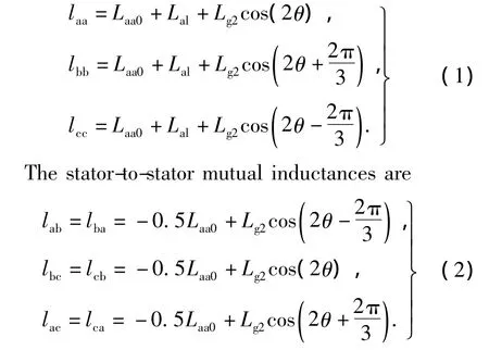
where θ is Electrical rotor angle;Laa0is component of the self inductance due to the space fundamental airgap flux;Lalis Additional component due to the armature leakage flux;Lg2is component of the self inductance due to rotor position dependent flux.
Phase self inductance is a function of 2θ,which means that for every electrical cycle the phase self inductance goes through two cycles.Fig.1 shows the 3 phase self inductance waveform,in which Lg2is equal to 6 mH,Laa0is equal to 0.5 mH.
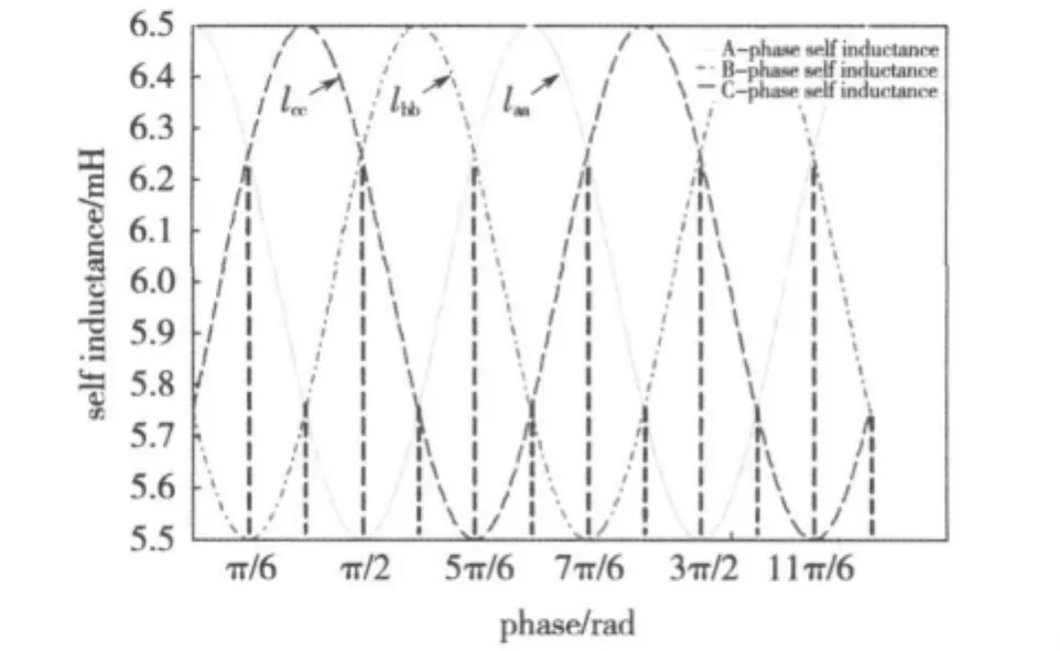
Fig.1 Variatin of A-phase,B-phase and C-phase self inductances at different rotor position angle
Further inspection of the self inductance profiles indicates that the division of the profiles into 12 regions coincides with a unique order of phase self inductance magnitudes for each region.In other words,by detecting the order of self inductance magnitudes,one can detect a region with a length of 30°within which the rotor position is located.This in turn will enable zooming into the targeted region for precise calculation of the rotor angle.These regions,along with the corresponding range of rotor position and the relationship among the magnitude of self inductances are illustrated in Table 1.
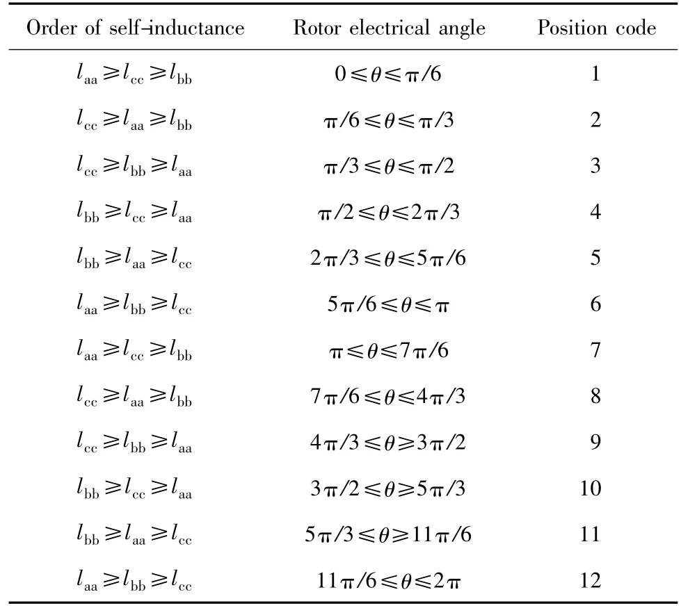
Table 1 The relation between the self inductance and the rotor position
2 Inductance comparision of IPMSM
To estimate the initial rotor position,voltage pulse is injected to the A and B windings by turning on switches,as shown in Fig 2.During this pulse-injecting interval T,phase A is connected to the positive dc bus by,and phase B is connected to the negative dc bus by,while phase C is floating without any current flow into it.During T and 2T,all switchs are switched off,the circuit is freewheeled;during 2T and 3T,switch,is on while phase C is open.In this case,considering the inertia of the motor and the load system,the motor remains motionless.In order not to saturate the machine,T,the duration of the application of test signal,is less than the average time constant of the system.From above analyse,the circuit diagram can be shown in Fig.3 and Fig.4.


Thecircuit equations of Fig.3 are


Where VSis the inverter switch on-state voltage drop.Substituting(4)and(5)into(3)gives


Fig.4Equivalent circuit when ,is on
The circuit equations of Fig.4 are
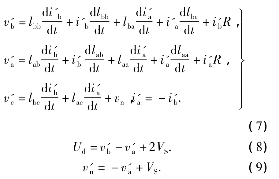
Where VSis the inverter switch on-state voltage drop.Substituting(8)and(9)into(7)gives

The voltage difference Δvc(t)between vc(t)and v'c(t+2T)shown in Fig.2 can be represented as

Substituting(6),(10)into(11)gives

Substituting(13)into(12)gives

Similarly,it can get

Therefore,it can be summarized that the winding self inductance values,laa,lbb,lcc,can be compared to each other by using(14),(15),(16).However,a single self inductance comparison can map into two opposite sectors as is evident in Table 2.For example,the condition,laa≤lbb≤lcc,can be identified the possible initial position in either π/6 ~ π/3 or 7π/6~4π/3 sectors.Thus,to determine which one of the two opposite sectors the rotor magnet pole actually locates,an additional process is required.This extra process is called polarity determination as described next.
3 Polarity determination process
There are two domains of position shown in Table 1.The kinds of estimated position have a difference of π rad between two.To identify the actual rotor position from two,The magnetic saturation effects is used on the saliency to track the magnet pole polarity[14-15].
It is well known that the associated inductance of stator windings for the linear(non-saturated)case is greater than that for the saturated case shown in Fig.5.The principle for estimation of magnetic pole position relies on the fact that a permanent magnet(the rotor)will also move an iron core closer to magnetic saturation.If the inductance is measured,more saturation means less inductance.If a current is added to the winding around the core,the current will either add to the saturation
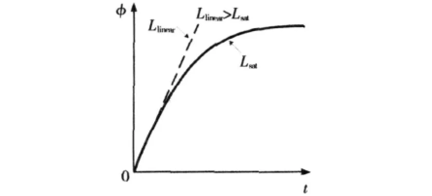
Fig.5 Inductance of stator windings,depending upon the position of rotor
Causing the inductance to decrease further,or subtract from the permanent.Magnet’s magnetomotive force(MMF),causing inductance to increase.
If a voltage is applied to a phase for a fixed period of time,and measure the peak current produced,then reverse the polarity,and repeat the measurement,by comparing the relative peaks you can determine the polarity of the permanent magnet.For example,in order to identify the possible initial position in either π/6 ~ π/3or 7π/6 ~ 4π/3 sectors,the voltage vectors v(100)and v(001)shown in Fig 6 and Fig 7 are applied to the motor during the long time TL.If iC> i'C,then the rotor position is π/6~π/3 sector.


Similarly,the other voltage vectors are provided to detect B-phase and C-phase current peaks,respectively.Table 2 shows the discrimination between two estimated positions for all domains.
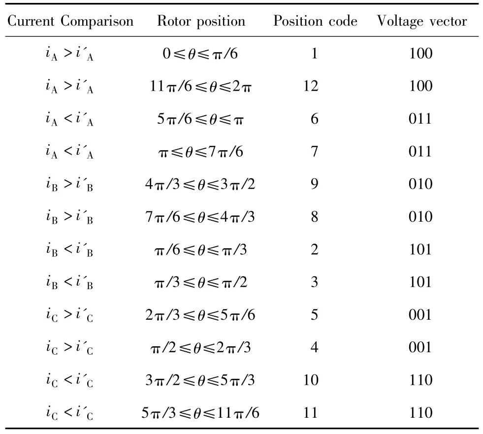
Table 2 Discrimination of polarity
4 Experimental verification
To verify the performance of the proposed initial position detection algorithms,experiments were carried out.The experimental system uses 16 bit microcontroller(dsPIC30-6010)with 30 V dc bus voltage shown in Fig 8.Two kinds of suitable sequence dc voltage rectangular pulses are applied from the inverter to the stator windings of the motor at standstill.The first voltage pulse which is for inductance comparison is applied with a short time duration,50 μs;To distinguish north magnetic pole between θ and θ+ π,another vector voltage which is for polarity determination is applied with a long time duration,150 μs.Considering the inertia of the motor and the load system,the motor remains motionless because the sum of torque of motor is almost zero.
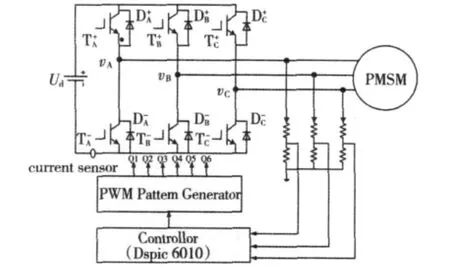
Fig.8 Experimental system configuration
Fig.9 shows the corresponding voltages and currents resulting from the injections at the actual position θ.From the figure,it can be seen that the comparisons of phase voltage are ΔVC<0,ΔVB>0,ΔVA>0.Based on equation(14),(15),(16),It can conclude that these is lbb≤laa≤lcc.According to Table 1,the estimate rotor position is in π/6≤θ≤π/3 or 7π/6≤θ≤4π/3 sector.By comparing the current peaks obtained,initial electrical rotor position,π/6≤θ≤π/3,can be discriminated.
Figs.10 shows the phase voltages and DC-bus currents resulting from the injections.It is indicated from the figures the voltage comparisons are ΔVC>0,ΔVB>0,ΔVA<0 and self inductance comparison is laa≤lcc≤lbb.So the possible rotor position is π /2≤θ≤2π/3 or 3π/2≤θ≤5π/3.However,the results of their current comparison show that the estimate initial position of the former is in the sector π/2≤θ≤2π/3.
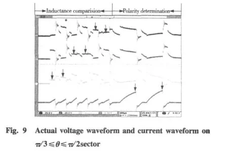

Fig.11 show the phase voltages waveform is same as Fig.9,but DC-link currents is different form Fig.9.Looking up the Table 2,it can be concluded that the estimate initial position is in the 3π/2≤θ≤5π/3 sector.
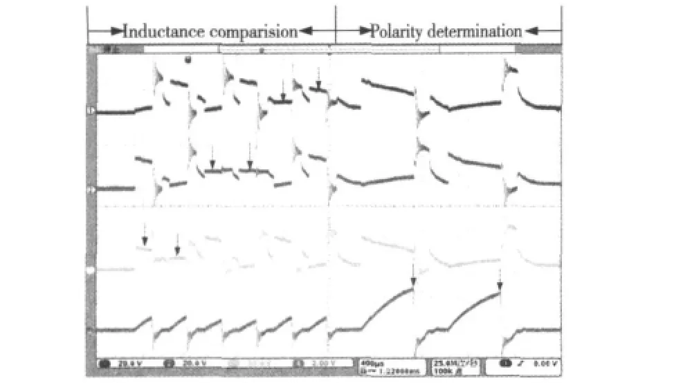
Fig.11 Actual voltage waveform and current waveform on 11π/6≤θ≤2π sector
5 Conclusions
In this paper,a simple initial rotor position estimation is introduced.It is based on the stator inductance variation due to the position of the rotor magnets.The magnet polarity is identified using the magnetic saturation effect and 30°resolution is achieved.The feasibility of initial rotor position estimation has been proved through experiments.
[1]TURSINI M,PETRELLA R,PARASILITI F.Initial rotor position estimation method for PM motors[J].IEEE Transactions on Industry Applications,2003,39(6):1630 -1640.
[2]Boussak M.Implementation and experimental investigation of sensorless speed control with initial rotor position estimation for interior permanent magnet synchronous motor drive.IEEE Transactions on Power Electronics,2005,20(6):1413 -1422.
[3]郑泽东,李永东,MAURICE Fadel,等.基于扩展Kalman滤波器的PMSM高性能控制系统[J].电工技术学报,2007,22(10):18-29.ZHENG Zedong,LI Yongdong,MAURICE Fadel,et al.High performance PMSM control system based on extended Kalman filter[J].Transactions of China Electrotechnical Society,2007,22(10):18-29.
[4]SCHROEDL M.Sensorless control of ac machines at low speed and standstill based on the“INFORM”method[C]//1996 IEEE Industry Applications Conference,Thirty-First IAS Annual Meeting,October 6 - 10,1996,San Diego,USA.1996,1:270-277.
[5]JANSEN P L,COLEY M,LORENZ R D.Flux,position,and velocity estimation in AC machines at zero speed via tracking of frequency saliency[C]//1995 European Conference on Power Electronics and Applications,September 18 - 21,1995,Sevilla,Spain.1995:154-160.
[6]HYUNBAE Kim,KUM-KANG Huh,LORENZ R D,et al.A novel method for initial rotor position estimation for IPM synchronous machine drives[J].IEEE Transactions on Industry Applications,2004,40(5):1369-1378.
[7]秦峰,贺益康,刘毅,等.永磁同步电机转子位置的无传感器自检测[J].浙江大学学报(工学版),2004,38(4):465 -469.QIN Feng,HE Yingkang,LIU Yi,et al.Rotor position sensorless estimation of permanent magnet synchronous motors[J].Journal of Zhejiang University(Engineering Science),2004,38(4):465-469.
[8]刘毅,贺益康,秦峰.基于转子凸极跟踪的无位置传感器永磁同步电机矢量控制研究[J].中国电机工程学报,2005,25(17):121-126.LIU Yi,HE Yikang,QIN Feng.Investigation of rotor saliency tracking based sensorless vector control drive for PMSM[J].Proceedings of the CSEE,2005,25(17):121-126.
[9]王丽梅,郭庆鼎.基于转子凸极跟踪的永磁同步电机转子位置的自检测方法[J].电工技术学报,2001,16(2):14-17.WANG Limei,GUO Qingding.Rotor position estimation for permanent magnet synchronous motor using saliency tracking selfsensing method[J].Transactions of China Electrotechnical Society,2001,16(2):14-17.
[10]SHEN J X,TSENG Kj.Analyses and compensation of rotor position detection error in sensorless PM brushless DC motor drives[J].IEEE Power Engineering Review,,2002,22(12):57-61.
[11]翟波,李建春.无位置传感器无刷直流电动机起动新方法[J]中国惯性技术学报,2007,15(3):347-350.ZHAI Bo,LI Jian-chun.New starting method for senseless brushless DC motor[J].Journal of Chinese Inertial Technology,2007,15(3):347 -350.
[12]KULKAMI A B,EHSANI M.A novel position sensor elimination technique for the interior permanent magnet synchronous motor drive[J].IEEE Transactions on Industry Applications,1992,28(1):144-150.
[13]TURSINI M,PETRELLA R,PARASILITI F.Initial rotor position estimation method for PM motors[J].IEEE Transactions on Industry Applications,2003,39(6):1630 -1637.
[14]LAI Yenshin,SHYU Fusan,TSENG Shaushian.New initial position detection technique for three-phase brushless DC motor without position and current sensors[J].IEEE Transactions on Industry Applications,2003,39(2):485 -491.
[15]MATSUI N.Sensorless PM brushless dc motor drives[J].IEEE Transactions on Industrial Electronics,1996,43(2):300-308.
