
Research on Performance of U Separator in Sand and Dust Test System
2011-03-09 11:57:02LIHongwei李宏伟WANGJun王浚ZHANGHua张华HANHaibo韩海波
Defence Technology 2011年2期
LI Hong-wei(李宏伟),WANG Jun(王浚),ZHANG Hua(张华),HAN Hai-bo(韩海波)
(1.School of Astronautic Science and Engineering,Beihang University,Beijing 100191,China;2.Baicheng Ordnance Test Center of China,Baicheng 137001,Jilin,China)
Introduction
The sand/dust environment has a serious destructive effect on the weapon systems,and it is a main environmental factor which leads to the failures of much equipment.In order to evaluate the operational performance and reliability of equipment in the sand/dust environment such as desert or drought regions,the different sand/dust test methods are prescribed in the military standards of many countries.
For the large sand/dust test system studied in this paper,its air flux is much lager than the common test cabinet,and the air temperature and humidity must meet the requirements prescribed in the technical files.So the pretreated air must flow circularly to perform the long-time test.In order to avoid the continuous increase in sand/dust concentration,ensure the test accuracy,and decrease the disadvantage effects,such as ablation and erosion of the key components such as fan vane caused by the sand particles,the particles contained in the air flow must be reclaimed efficiently.Therefore,it is necessary to study the gas-solid twophase flow field and separate efficiency of separator,and provide the basis for the design and test of sand/dust separate system.
Because the multiphase flow inside the separator is a complicated turbulent flow,it’s quite difficult to solve it by using the equations of flow directly.Thus,the theoretical analysis method can not get a satisfactory result.Currently,the experimental test method can not meet all the requirements of similar parameters and similar law,and has the disadvantages of wall effect,bracket interference and measurement error,etc,so the results of experimental method have their inherent limitations.By creating a reasonable mathematical model for flow process and computing,the numerical simulation method can reveal the structural characteristics of a complex flow field,and study the influence principles of gas-solid two phase flow and its separate mechanism and the effect of some parameters on the distribution of flow field.The results can be used as the basis of optimization and amplification design,so the numerical simulation method based on the results of experimental tests and theoretic analyses is a valid method in the study of complex flow[1-2].
1 Sand/Dust Test System
Commonly,the circular wind tunnel layout is adopted in sand/dust test system.The air flows circularly,and the sand/dust material is injected into the air just before it enters the test segment.In order to get a perfect separate efficiency in the separate segment,the air velocity is decreased to about 1/3 of its value in test segment through pressure expansion.The large sand/dust test system studied in this paper is composed of fan,circular wind tunnel,sand/dust feed/recovery system,sand/dust injection system,air-conditioning system,measuring/control system.The layout of wind tunnel is shown in Fig.1.
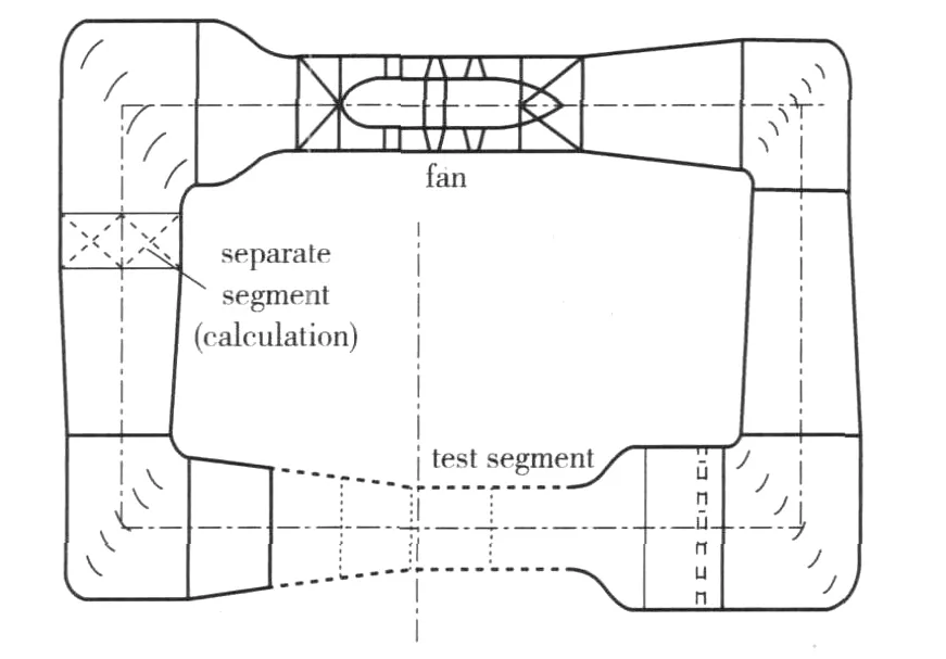
Fig.1 Sketch map of large sand/dust test tunnel
2 Modeling and Analysis of U Inertia Separator
2.1 Physical Model
The cross section of U inertia separator studied in this paper is 1 m×1 m,and the length is 1.3 m along the flow direction.The first row of U separate components is fixed at 0.5 m from the separator entrance.The width and depth of components are both 40 mm,and the transverse and longitudinal spaces between components are also 40 mm.Since the calculating region is a regular cuboid and the inner flow matches the symmetrical characteristic,just 1/2 of the inner flow field of separator is calculated to improve the calculating efficiency.The physical model of separator is shown in Fig.2.

Fig.2 Physical model of separator
2.2 Mathematical Model
Commonly,there are two approaches to solve multiphase stream,the Euler-Euler approach(two-phase/multiphasefluid model)and theEuler-Lagrange approach(particle trajectory model or discrete phase model)[3-4].Because the highest concentration required in sand blow process is merely 2.2 ±0.5 g/m3,and the concentration required in dust blow process is 10.6 ±7 g/m3,the volume occupied by sand/dust particles is much less than that of gas phase,the effect of particles on the flow field is slight.All the flow characteristics match the requirement of discrete phase model(DPM),so DPM is adopted in calculation.In this model,the gas phase(air)is treated as a continuum,and its flow regulation is described by two-phase coupled Navier-Stokes equations.Meanwhile,the moving trajectory of each particle is described in Lagrange coordinate.
In this simulation,the standard k-ε model is adopted,and its equations are as follows:

where Gkis the turbulence kinetic energy caused by the mean gradient of velocity,Gbis the turbulence kinetic energy caused by the effect of flotage,YMis the effect of the pulsating expansion of compressible turbulence on total dissipation rate,and the coefficients of turbulence viscosity μt= ρCμk2/ε;C1ε,C2εand C3ε,are experiential constants[3-5].
1)The forces act on the particles in flow field
Since Lagrange method is used to simulate the moving trajectories of many discrete single particles,and get the related solid phase parameters by statistical average means,it’s necessary to analyze the various forces acting on the particles in flow field,and establish the moving equations[1]. During the separate process,the forces acting on the particles are complex,including fluid drag force(viscous resistance),gravity,pressure gradient force,additional mass force,Saffman force,Magnus force and Basset force,etc.The gravity and fluid drag force are the main forces during separate process,while the other forces are much less so that they are negligible in the simulation.
2)Random particle trajectory model
(1)Moving equation of particles
The particle trajectories are obtained by integrating the force differential equations in Lagrange coordinates.The force balance equations can be written as(for X direction in Cartesian coordinates):
where FD(u-up)is the drag force per unit particle mass,where FD=3μCDRe/(4ρpd2p)(s-1);u is the velocity of fluid(m/s),upis the velocity of particles(m/s),μ is the dynamic viscosity of fluid(Pa·s),ρ is the density of fluid(kg/m3),ρpis the density of particle(kg/m3),dpis the diameter of particle(m),Relative Reynolds number Re= ρdp|up- u|/μ.Drag force coefficient CD=a1+a2/Re+a3/Re,where a1,a2,a3are constant,and Fxis an additional acceleration term.
(2)The turbulent diffusion of particles
Considering the turbulent diffusion of particles,the random trajectory model is adopted in simulation,and the velocity of fluid in trajectory equations is instantaneous velocity,+u'(t),the random effect of turbulent flow of particles is considered by calculating a great deal of particle trajectories.
3 The Results and Discussion of Calculation
In this paper,23 cases are calculated at various air velocities,and the rows of separate components are 2,3,4,5 and 6,respectively.The density of sand/dust material is 2 650 kg/m3,and the distribution of particle diameter is shown in Tab.1.
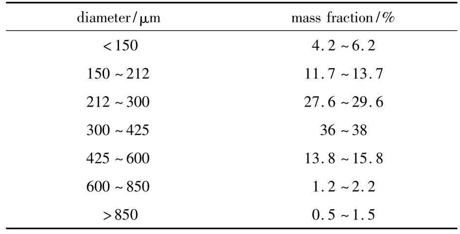
Table 1 The distribution of particle diameter
3.1 The Separate Efficiency for Different Rows of Separate Components
The separate efficiency at different air velocity is calculated,and the rows of separate components are 2,3,4,5 and 6,respectively.The inner flow field velocity nephogram of typical separator with 4 rows of separate components is shown in Fig.3.From the figure it can be seen that a stagnant region forms apparently in the U separate components,and the stagnant region in the next row of components is on the lower reaches of the high speed air flow between the upper separate components.
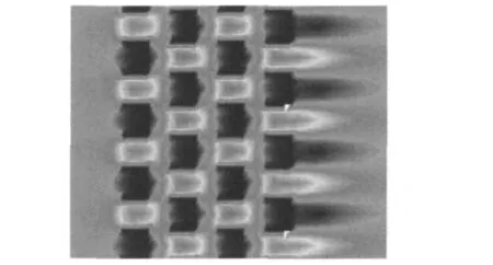
Fig.3 Velocity distribution of flow field in the separator at z=20 cm
Fig.4 shows the moving trajectories of particles when the air velocity is 9 m/s and 3 rows of separate components are used in the separator,where the en-trance and exit of separator are represented by the rectangles located at the left and right sides,respectively.The moving direction of particles does not change apparently since they enter into the separator along with the air flow.This phenomenon indicates that 9 m/s air flow has a relative higher ability to carry the sand/dust particles.It is obvious that,in the stagnant region of U components,most particles move slowly and concentrate together,and the particles move slowly toward the bottom of separator by the action of gravity.It can be found from observing the trajectories of particles that,after impacting with the components,some particles rebound and move upstream,but resume the forward moving gradually by the action of air flow.In this process,the velocities of most particles along the main air flow direction decrease seriously,and the particles are recovered when they drop onto the bottom of separator.At the same time,few particles are re-carried by the main air flow and enter into the next row of separate components.Some particles circumambulate the components along with the air and escape directly.Passing through 3 rows of separate components,the most particles contained in the air flow are recovered,and the trajectories of escaped particles concentrate near the bottom and appear drop trend obviously.Obviously,the U inertia separator is efficacious even though the air velocity is high.
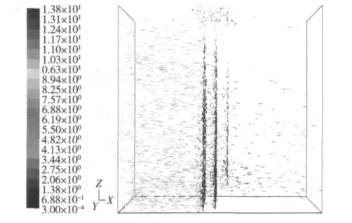
Fig.4 Trajectories of particles
To analyze how the effect of row number of separate components on the efficiency and provide a basis for the structure optimization,the efficiencies of several separators with various rows of components are calculated.The concentration of sand/dust particles in components is shown in Fig.5,and the separate efficiencies at the air velocity of 4 m/s are shown in Fig.6.From Fig.5 and 6 it can be known that the efficiency of 5throw of component is much less compared with the front 4 rows of components,its contribution to the increase in total separate efficiency is just 0.22%.That is,while the row number of components reaches 4,the continuous increase in the row number of components makes little improvement on separate efficiency.Particularly,for the separate efficiency of small diameter particles(dust),the additional rows of components make almost no advancement on the separate efficiency.But the increase in row number increases the pressure drop apparently.In the case of the air velocity of 4 m/s,while the row number increases from 3 to 5,the pressure drop boost rapidly from 203-364 Pa.
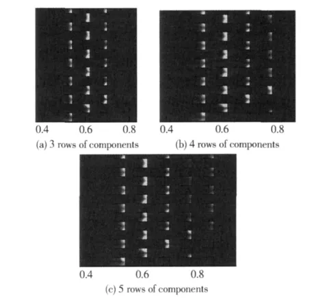
Fig.5 Concentration distribution of sand/dust at z=20 cm(the air velocity is 9 m/s)
3.2 The Influence of Air Velocity on the Separate Efficiency
For the inertia separator,high air velocity means the large kinetic energy of particles.When the air flow swerves,the centrifugal acceleration is large so the particles are easily separated.On the other hand,high air velocity also means that the air flow has a stronger ability to carry the particles,and this results in moving away with air flow.In Fig.3,we can observe an apparent stagnant region in U components.In this region,the air flow affects the moving of particles slight-ly,and the gravity is the main force acting on the particles.After the particles impact on the U component,they move slowly,and sink onto the bottom of separator gradually.When the air velocity is too high,the rebound velocity of particles impacted on the components increases accordingly.A part of large particles may escape from the stagnant region,and re-carried by the main air flow to enter the next row of components or penetrate the separator.The moving trajectories of particles show the escaping course clearly.
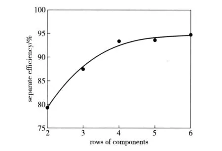
Fig.6 Efficiencies of separators with various rows of separate components
The effect of air flow velocity on particles with different diameter is simulated,as shown in Fig.7.The curves labeled“a-g”represent the separate efficiencies of 7 species of particles with diameters from larger than 850 μm to smaller than 150 μm.From the results we know that,with the increase in air velocity,the following characteristic of small particles increases because the carrying ability of air flow is enhanced.The separate efficiency of particles smaller than 212 μm diameter decreases evidently,but the decreasing trend is slacken off while the air velocity reaches to 8~9 m/s.The separate efficiency of particles with 300 μm diameter also decreases,but the rate is smooth relatively.Even the air velocity is 9 m/s,the separate efficiency still remains at a relative high level.For the larger than 425 μm particles,the separate efficiency is affected by air velocity slightly,when the rows of separate components are more than 4,the separate efficiency is prominent.
The results indicate that,this type of separator may separate lager sand particles efficiently,and has been proven in the practical application,but the separate efficiency of particles with smaller than 212 μm diameter is unsatisfactory.Particle trajectories show that,the concentration of particles near the wall of separator is much higher than that in the interior.It is shown that inner wall of separator affects the efficiency greatly,and the improved inner structure of separator can increase the efficiency.
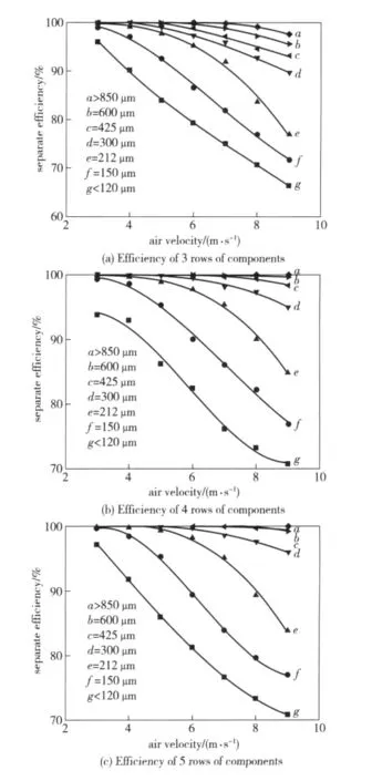
Fig.7 Effect of air velocity on separate efficiencies of different particles
4 Conclusions
1)The results of simulation analysis and practice application indicate that the U inertia separator is effi-cacious in particle separate field,and in the case of relative high air velocity,it has a good performance in the separation and recovery of large particles.
2)In order to get a perfect separate efficiency,it’s enough to fix 4 -5 rows of separate components in the separator.Redundant rows of components have little contribution to the improvement on the efficiency but an apparent increase in the pressure drop.
3)Air velocity affects the separate efficiency of little particles evidently.The main reason is that the following characteristic enhances rapidly along with the acceleration of air flow.When this kind of separator is adopted in the occasion where requires a rigid separate efficiency,the measures should be taken to improve the efficiency.
[1]CEN Ke-fa.The theories and technologies of gas-solid separation[M].Hangzhou:Zhejiang University Press,1999:278-279.(in Chinese)
[2]YAN Chao.The methods and application of computational fluid dynamics[M].Beijing:Beihang University Press,2006:10-14.(in Chinese)
[3]JIANG Fan.The advanced application and example analyze of fluent[M].Beijing:Tsinghua University Press,2008:140 -183.(in Chinese)
[4]WEN Zheng.The course of application about fluid calculation of fluent[M].Beijing:Tsinghua University Press,2009:343 -352.(in Chinese)
[5]ZHANG Li-zhen.Study on particle flow character in gas/solid two-phase wind tunnel[J].Journal of System Simulation,2007,14(19):3200 -3202.(in Chinese)
[6]Shaaban S.Numerical optimization and experimental investigation of the aerodynamic performance of a threestage gas-solid separator[J].Chemical Engineering Research and Design(in press).
[7]Mathiesen V,Solberg T,Hjertager B H,et al.An experimental and computational study of multiphase flow behavior in a circulating fluidized bed[J].International Journal of Multiphase Flow,2000,26:387 -419.
猜你喜欢
科教新报(2023年25期)2023-07-10 05:59:40
快乐作文(1.2年级)(2022年12期)2023-01-27 09:29:07
宝藏(2022年2期)2022-07-30 07:41:00
宝藏(2022年2期)2022-07-30 07:41:00
运动精品(2022年1期)2022-04-29 05:56:32
红蜻蜓·低年级(2021年12期)2021-12-19 11:13:03
小天使·一年级语数英综合(2020年3期)2020-12-16 02:56:12
作文周刊·小学一年级版(2020年16期)2020-06-12 11:40:31
科教新报(2020年2期)2020-02-14 05:57:58
河北书画研究(2019年1期)2019-09-25 07:34:26

- Defence Technology的其它文章
- Experimental Investigation on Combustion Performance of Solid Propellant Subjected to Erosion of Particles with Different Concentrations
- A Real-time Monitoring System for Tire Blowout or Severe Leakage
- A Support Vector Machine Based on Bayesian Criterion
- Prefix Subsection Matching Binary Algorithm in Passive RFID System
- An Orthogonal Wavelet Transform Fractionally Spaced Blind Equalization Algorithm Based on the Optimization of Genetic Algorithm
- An Evaluation Approach for Operational Effectiveness of Anti-radiation Weapon