ANALYTICAL STUDY OF WAVE MAKING IN A FLUME WITH A PARTIALLY REFLECTING END-WALL*
ZHOU Bin-zhen
State Key Laboratory of Coastal and Offshore Engineering, Dalian University of Technology, Dalian 116024, China, E-mail: zhoubinzhen4827@163.com
NING De-zhi
State Key Laboratory of Coastal and Offshore Engineering, Dalian University of Technology, Dalian 116024, China
State Key Laboratory of Hydrology-Water Resources and Hydraulic Engineering, Nanjing Hydraulic Research Institute, Nanjing 210029, China
TENG Bin, CHEN Li-fen
State Key Laboratory of Coastal and Offshore Engineering, Dalian University of Technology, Dalian 116024, China
Based on the eigenfunction expansion technique, the wave generation by a piston wave maker in a wave flume with a partially reflecting end-wall is studied. The corresponding velocity potential and wave elevation in the flume are obtained. The present analytical solution is verified by the numerical results obtained from a time-domain higher-order boundary element method in a closed flume. Numerical experiments are further carried out to study the difference between the partial/full reflection boundary and the transmission boundary and the effects of the reflection coefficient and the motion period of the wave maker on the wave height. Meanwhile, the natural frequency of the wave flume can be obtained from the analytical expression. The resonance occurs when the motion frequency is equal to the natural frequency. Even the partial reflection of the end-wall in the wave flume experiments has a great influence on the wave height, therefore, inaccurate measurements would be resulted in long-time simulations, especially when the wave frequency approaches the wave flume natural frequency. The present study can serve as a guidance for the physical experiment in wave flumes.
wave flume, wave maker, partially reflecting end-wall, resonance, eigenfunction, analytical study
1. Introduction
The wave generation in flumes is of considerableimportance for offshore and coastal engineering. Many studies have been devoted to wave maker theories based on analytical and numerical methods. For example, Liu et al.[1]applied a theoretical method to study an active absorbing wave maker system. Schaffer and Steenberg[2]developed a complete second-order wave maker theory for the generation of multidirectional waves in a semi-infinite basin. With eigenfunction expansions and Fast Fourier Ttansform (FFT) algorithm, Wojciech and Maciej[3]proposed a semi-analytical nonlinear wave maker model to study the generation and propagation of transient nonlinearwaves in a wave flume. Spinneken and Swan[4]proposed a second-order wave maker theory for regular waves using the force-feedback control. With the eigenfunction expansion technique, Zhou et al.[5]obtained a linear analytical solution for wave generation by a piston wave maker in a deep step-type wave flume. He[6]applied the Boundary Element Method (BEM) combined with the time-stepping scheme to study the wave generation by the large amplitude oscillation of a rocker flap wave maker. Koo and Kim[7]utilized the fully nonlinear 2-D numerical wave tank to simulate the nonlinear wave and force generated by a wedge-shape wave maker. Yang et al.[8]employed a time-domain numerical model to simulate the wave making by a moving ship based on Green’s theorem. Based on a fully nonlinear numerical wave tank model, Zhou et al.[9]and Ning et al.[10]carried out a numerical simulation of waves generated by a piston wave maker. In the above studies, it is noted that the end walls of wave flumes are all defined as the transmission boundary. However, it is actually difficult for outgoing waves to be completely dissipated at the end of a physical flume. And some partial reflections may exist, which would result in inaccurate measurements in a long-time experiment due to the multi-reflections between the wave flume end and the wave maker. Therefore, it is necessary to study the effects of the partial reflection of the wave flume end on experimental results.
Many investigations were carried out on the prediction of the wave field in a harbor with partial reflection boundaries. For example, Hammanaka[11]studied a harbor wave field for a range of boundary conditions, including partial reflection. Lee and Williams[12]presented a numerical model for the wave field due to the diffraction of multidirectional random waves in a harbor of arbitrary shape with partial reflection boundaries. Tan et al.[13]considered wave fields in harbors using a mesh generation software and the mid-slope equation with partial reflection boundary conditions at the wall boundary considered. Ghassan et al.[14]discussed the interaction of linear water waves with a moored floating breakwater with a leeward boundary composed of a vertical wall.
In this article, an exact analytical solution is derived for the wave generation by a piston wave maker with a partial reflection wave flume end, based upon the usual assumptions of the linearized water-wave theory and the two-dimensional motion. The fluid is assumed to be ideal, the motion irrotational, and the wave amplitude small compared with the wavelength and the fluid depth. The method of eigenfunction expansions is adopted to calculate the velocity potential and the wave elevation. Moreover, numerical experiments are carried out to see the difference between the partial reflection boundary and the transmission boundary, and the effects of the reflection coefficient and the motion period of the wave maker on the wave height. Meanwhile, the natural frequency of the wave flume is obtained from the analytical solution. It is shown that the resonance occurs in a closed wave flume when the motion frequency is close to the natural frequency, with large waves for partial reflection boundaries.
2. Mathematical model
2.1Governing equation
A wave flume with a vertical end-wall in water of depthdis considered here, as shown in Fig.1. A Cartesian coordinate system is adopted with the origin in the plane of the undisturbed free surfacez=0, with thez-axis positive upwards and thex-axis positive rightwards. At the left end of the wave flume, a monochromatic wave is generated by a piston wave maker with the following motion:


Fig.1 Definition sketch
The fluid is assumed to be inviscid and incompressible, and the motion is irrotational. It is further assumed that the motion is a simple time-harmonic with the angular frequencyω, the time parameter can be separated and the velocity potentialΦ(x,z,t) can be rewritten in the following form:

whereφ(x,z) is the complex spatial velocity potential with the unit amplitude motion of the wave maker.
2.2Boundary conditions
The velocity potentialφ(x,z) is governed by the Laplace equation with the free surface condition, the incident boundary condition and the partial and full reflection boundary conditions.
2.2.1 Free surface condition
The linear free surface boundary condition atz=0can be written as:

2.2.2 Incident boundary condition
The condition says that the normal derivative of the velocity potential is equal to the wave maker velocity on the wave maker surface, which can be written in the following form:

2.2.3 Reflection boundary condition
On the flume bottom, the full reflection boundary condition, i.e., the non-penetrating boundary condition, is

2.2.4 Partial reflection boundary condition
In many numerical simulations, the full reflection or the transmission boundary conditions are applied at the right wave flume end. Actually, a partial reflection is the case at the physical flume end. In the present model, a partial reflection boundary condition is imposed by using a mixed boundary condition[14], i.e.,

whereBis the flume length,kis the wave number andα(=α1+iα2) is a complex transmission coefficient and can be expressed by the conventional reflection coefficientKrand a reflection phase angleβas follows


Ghassan[14]indicated that the phase angleβhas a minor influence on the results. Therefore, one may assume no phase shift between the incoming waves and the reflected waves, i.e.,β=0. Hence, the partial reflection boundary condition in Eq.(7) can be expressed as:

3. Mathematical analyses
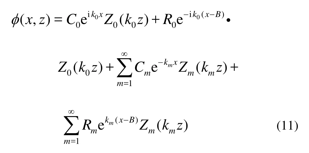
The velocity potential, satisfying the linear free surface condition and the non-penetrating condition on the seabed bottom, can be written in the following form:

where the first term is the rightward waves, the second is the leftward waves, the third is the evanescent waves exponentially decayed far from the wave maker and the last is the waves exponentially decayed away from the vertical sidewall,CmandRm(m=0,1,…) are the unknown coefficients. The vertical eigenfunctionsZm(kmz) form an orthogonal set in[−d,0] and are defined as:

where wave numbersk0andkmsatisfy the following dispersion equations, respectively,


In order to evaluate the unknown coefficientsCmandRm, we take (M+1) terms (0,1,…,M) forCmandRm.
By substituting Eq.(11) into the wave maker boundary condition Eq.(5), the following relation can be obtained:

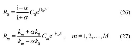
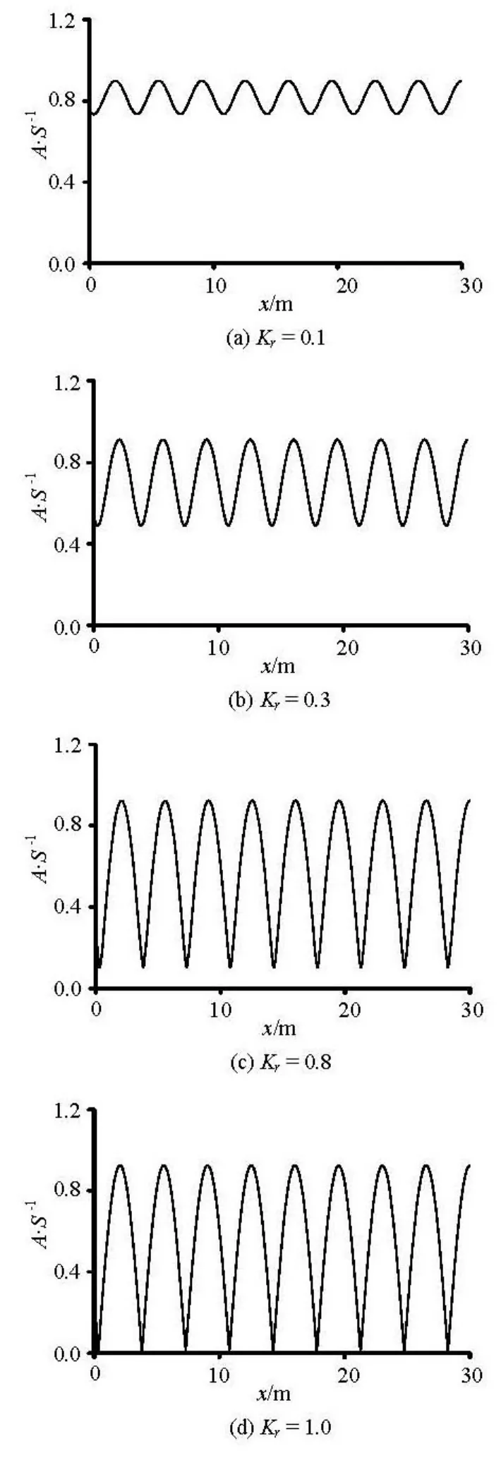
Multiplying both sides of Eq.(16) by the vertical eigenfunctionsZm(kmz) and integrating over the interval −d Equations (17) and (18) can be rewritten in the following forms: Substituting Eq.(11) into the partial reflecting boundary condition Eq.(10), the following relation can be obtained Multiplying both sides of Eq.(23) by the vertical eigenfunctionsZm(kmz) and integrating over the interval −d Equations (24) and (25) can be rewritten in the following forms: By substituting Eqs.(26) and (27) into Eqs.(21) and (22), the following relation can be obtained The unknownsCmandRm(m=0,1,…,M) can be obtained from Eqs.(26)-(30). Thus the velocity potential can be obtained by substitutingCmandRminto Eq.(11). Based on the linear wave maker theory, the wave surface elevation in the wave flume is ForKr=0, it follows thatα=iandR0=0. In this case, the end of the wave flume satisfies the transmission boundary condition, and the wave amplitude agrees with the existing theoretical expression as follows ForKr=1, it follows thatα=0 andR=Ceik0B. In this case, the wave elevation can be 00written as follows if we ignore the evanescent waves: From Eq.(33), it can be easily deduced that the wave amplitude reaches the maximum atx=B−nL/2.0(n=0,1,2,…) and the minimum atx=B−nL/4.0 (n=1,3,5,…), respectively, withLbeing the wavelength. We now carry out some numerical simulations to illustrate the analytical method discussed above. First, some numerical experiments are performed to check the convergence of eigenfucntions in Eqs.(11) and (31). It shows that a converged solution can be obtained whenMis truncated with 10 terms. Two special casesKr=0 and 1.0 are then considered. The former one (Kr=0) shown in Eq.(32) is validated by a comparison with the existing analytical expression. For the latter one (Kr=1), a numerical wave tank based on the time-domain higher-order boundary element method (THOBEM, Ning and Teng[15]) is used for the comparison. For the frequency-domain method, a steady result can be obtained. But for the time-domain method, the result obtained includes not only the steady solution but also the transient solutions. The transient effects come from the resonant waves in the present case and are rapidly dissipated in the physical flume because of even a very small viscosity. In order to compare with the present steady solution, a damping mechanism invented by Kim[16]is used in the THOBEM to eliminate the transient effects with the corresponding damping coefficient1μ′ of 0.06. A closed wave flume with lengthB=5.0m and water depthd=1.0m is considered here. The motion period and the amplitude of the wave maker areT=2.5s andS=0.01m, respectively. From the above known conditions, the wavelengthL=6.985m is obtained. Fig.2 Time history of wave elevation atx=B Figure 2 shows the time history of the wave elevation at the wave flume (x=B). The comparisonsof the proposed analytical solution with numerical results from the HOBEM with linear boundary conditions are also given in the figure. From the figure, it can be seen that the numerical wave elevation eventually reaches that of harmonic oscillations, and the results given by the two methods agree well with each other, which validates the theoretical method presented in this article for the full reflection end-wall. Fig.3 Distribution of wave amplitudeAat different positions Further numerical calculations are carried out in a wave flume with lengthB=30.0m and water depthd=1.0m in the following section. Figure 3 is the distribution of the wave amplitudeAalong the line of symmetry of the flume forT=2.5sand different reflection coefficients (Kr=0.1, 0.3, 0.8, 1.0). From the figure, it can be seen that the distribution of the wave amplitude is non-uniform, and varies in a harmonic way with the distance from the wave maker. The oscillating amplitude increases with the increasing of the reflection coefficient. The wave amplitude reaches the maximum at positionsx=B−nL/2.0 (n=0,1,2,…) and reaches the minimum at positionsx=B−nL/4.0 (n=1,3,5,…) for different reflection coefficients. The minimum wave amplitude is zero for the full reflection condition. Figures 5(a) and 5(b) give the distribution of the parameterKAversus the reflection coefficientKr. From the figure, it can be seen that the parameterKAincreases with the increasing of the reflection coefficientKr, and the increasing value is related to the motion periodT. Figure 5(a) shows that when the motion period is near the natural period, the parameterKAis greater than the corresponding to other periods. It can be seen from Fig.5(b) that the parameterKAreaches the maximum when the motion period is equal to the natural period, and the resonance occurs forKr=1. Therefore, the partial reflection of the end wall in the wave flume also has a great influence on experimental results. Appropriate measures should be adopted to reduce such experimental errors. Fig.4 Distribution of the parameterKAwith periodT Fig.5 Distribution ofKAwith the reflection coefficientKr [1] LIU Shu-xue, WU Bin and LI Mu-guo et al. Irregular active absorbing wave maker system[J].Journal of Hydrodynamics, Ser. A,2003, 18(5): 532-539(in Chinese). [2] SCHAFFER H. A., STEENBERG C. M. Second-order wave maker theory for multidirectional waves[J].Ocean Engineering,2003, 30(10): 1203-1231. [3] WOJCIECH S., MACIEJ P. Generation and propagationof transient nonlinear waves in a wave flume[J].Coastal Engineering,2008, 55(4): 277-287. [4] SPINNEKEN J., SWAN C. Second-order wave maker theory using force-feedback control. Part I: A new theory for regular wave generation[J].Ocean Engineering,2009, 36(8): 539-548. [5] ZHOU B. Z., NING D. Z. and TENG B. et al. Analytical study on wave making in a deep wave flume in step-type[J].Wave motion,2010, 47(1): 1-11. [6] HE Wu-zhou, DUAN Wen-yang. Fully nonlinear calculation of 2-D water wave generated by rocker flap wavemaker[J].Journal of Hydrodynamics, Ser. A,1996, 11(1): 35-42(in Chinese). [7] KOO W. C., KIM M. H. Numerical simulation of nonlinear wave and force generated by a wedge-shape wave maker[J].Ocean Engineering,2006, 33(8): 983-1006. [8] YANG Xiang-hui, YE Heng-kui and FENG Da-kui et al. Computation research on wave making of moving wigley hull in time domain[J].Journal of Hydrodynamics,2008, 20(4): 469-476. [9] ZHOU Bin-zhen, NING De-zhi and TENG Bin. Realtime simulation of waves generated by a wave maker[J].ChineseJournal of Hydrodynamics,2009, 24(4): 406-416(in Chinese). [10] NING D. Z., ZHOU B. Z. and TENG B. et al. Numerical simulation of nonlinear regular and focused waves generated by a piston wave maker[C].The 5thInternational Conference on Asian and Pacific Coasts.Singapore, 2009. [11] HAMMANAKA K. I. Open, partial reflection and incident-absorbing boundary conditions in wave analysis with a boundary integral method[J].Coastal Engineering,1997, 30(3): 281-298. [12] LEE H. S., WILLIAMS A. N. Boundary element modelling of multidirectional random waves in a harbour with partially reflecting boundaries[J].Ocean Engineering,2002, 29(1): 39-58. [13] TAN Li, TENG Bin and ZHAO Ming. Wave field computation in harbors using the mesh generation software and the mild-slope equation[J].The Ocean Engineering,2004, 22(4): 107-114(in Chinese). [14] GHASSAN E., RAFIC Y. and PASCAL L. The effects of reflection coefficient of the harbor sidewall on the performance of floating breakwaters[J].Ocean Engineering,2008, 35(11): 1102-1112. [15] NING D. Z., TENG B. Numerical simulation of fully nonlinear irregular wave tank in three-dimension[J].International Journal for Numerical Methods in Fluids,2007, 53(12): 1847-1862. [16] KIM Y. H. Artificial damping in water wave problems I: constant damping[J].International Journal of Offshore and Polar Engineering,2003, 13(2): 88-93. December 4, 2009, Revised January 14, 2010) * Project supported by the Open Fund of Key Laboratory of Hydrology-Water Resources and Hydraulic Engineering (Grant No. 2009491611), the National Natural Science Foundation of China (Grant Nos. 50709005, 10772040 and 50921001) and the Major National Science and Technology Projects of China (Grant No. 2008ZX05026-02). Biography:ZHOU Bin-zhen (1984-), Female, Ph. D. NING De-zhi, E-mail: dzning@dlut.edu.cn 2010,22(3):402-409 10.1016/S1001-6058(09)60071-8


4. Wave elevation


5. Numerical results and analyses


6. Conclusion


