Experimental investigation on combustion stability of hybrid rocketmotors①
ZHANG Yan,WANG Liang,SUN De-chuan,DU Xin
(College of Astronautics,Northwestern Polytechnical University,Xi'an 710072,China)
0 Introduction
The oscillation combustion of rocketengine is caused by the coupling of combustion and fluid dynam ic processes.Oscillation combustions in solid rocketmotor and liquid rocket engine are mostly high-frequency acoustic oscillations,which will cause catastrophic accidents.Oscillation combustions in the HRM are generally low-frequency combustion oscillations(f<200 Hz)and non-acoustic“overall” vibration,which will not cause catastrophic accidents as rapidly as the high-frequency sound oscillation.Buta long-time low-frequency oscillation can lead to the loosing of liquid pipe fittings,valves and other joints and leaking.What's more,low frequency oscillation combustion may also significantly decrease HRM performance.For avoiding and eliminating vibration combustion in HRM,a lot of research work had been done.Boardman and Carpenter,for examp le,studied the oscillation form in LOX-HTPB.
HRM with diameter of 280 mm and diameter of 610 mm[1],proved the existenceof two kinds of low-frequency oscillation combustion forms:one is the non-acoustic oscillation caused by the coupling of the supply system of liquid and the chamber;the other is associated with the stable structureof the flame at thehead of chamber,including non-acoustic oscillation and acoustic oscillation modes.
Atpresent,research on the oscillation combustion in HRM ismostly focused on the low frequency and non-acoustic areas.Based on the prelim inary studies[2-3]and the experiment study of 85%H2O2-PE HRM,this paper probes into the measures to avoid the coupling of HRM oxidizer supp ly system and the engine chamber,hence e-liminate this kind of low frequency non-acoustic oscillation combustion.
1 Low-frequency oscillation combustion spectrum characteristic of HRM
Pressure curves fraction(Fig.1) of certain 85%H2O2-LDPE motor head was analyzed by the Fast Fourier spectrum analysismethod.

Fig.1 Pressure curves of certain testmotor
From Fig.2,we can see a Fourier component in the frequency range of 1~2 Hz, of which the phase angle is about4π.Moreover,from Fig.1,we can estimate that the frequency of low-frequency oscillation is 0.7~2.0 Hz.

Fig.2 FFT analysis of p ressure curves of the firstm otor
From the FFT analysis ofmotor test pressure curves and direct frequency estimation,we canmake sure that the low-frequency oscillation frequency ofmotor is below 2.0 Hz.Moreover,from the test curves,we can see that the oscillation frequency is the same in themotor head,afterbody and the inletof the oxidizer,and the oscillation combustion of the motor is overall oscillation process.Such oscillation process in the chamber can be analyzed by one dimensional linear acoustics stability.
The one dimensional linear acoustics corresponding frequency of combustion can be expressed as:
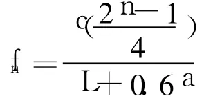
The low-frequency unstable frequency produced in the experiment is not in agreement with experimental check pure acoustics process,which is due to the fact that pure acoustics response analysis failed to couple with the combustion and energy injection process.
The computational condition is that the diameter of the chamber is 90mm,the length is300mm,the flow rate of gas oxidizer is 0.35 kg/s.The tested pressure oscillation frequency is 1.75 Hz,the oscillation frequency obtained in the paper is1.68Hz(Fig.3),which hasa good agreementwith the experiment data(Fig.4).

Fig.3 p-t curve from the simulated results

Fig.4 Comparing curve between oscillation frequency test and numerica l simu lation
2 Test system of HRM and testmotor
The test system of HRM consists of six parts:
(1)Gas source and gas,electric control subsystem;
(2)Increase and relief system of tank,emergency discharge,liquid-oxidants feed system,blowing system;
(3)Gas and liquid supply subsystem;
(4)HRM(inside diameter of chamber:108 mm);
(5)Flexible test fixture of calibration in situ;
(6)Virtual testing and videomonitoring subsystem.
Testprocessand data collection is controlled by the computer,using the Labview software and data acquisition-control panel.
Test motor mainly contains liquid nozzle,catalytic chamber,LDPE fuel grain,secondary chamber,graphite nozzle,and other parts composition(as shown in Fig.5),w ith 85%H2O2as the oxidant and LDPE as solid fuels.The catalytic decomposition of H2O2can ignite LDPE solid fuel with its high-temperature decomposition gas,and the motor ignition system can be omitted.The catalytic chamber is self-designed using silver-plated nickel screen(200 mesh)superimposed along the axis.The catalytic ability of catalytic bed is associated with catalytic net mesh number and effective silver-p lated area.LDPE grain ismanufactured from the bar machining forming,and can be freely filled in themotor.
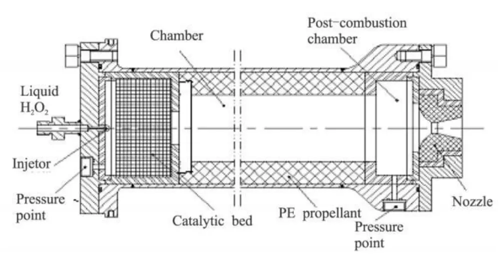
Fig.5 85%H2O 2-PE HRM sketch
The working process of the test set is as follows:checking if all electromagnetic valves closed;filling H2O2;turning on thenitrogen gas compression source and driving gas source to supercharge the H2O2tank;sending start signal to turn on the electromagnetic valve;the test system starts to record data;H2O2pass through the electromagnetic valve and spray nozzle into the catalytic chamber,being atomized and decomposing to water vapor and oxygen(the high temperaturegases);in the chamber,the high temperature cause the solid fuel LDPE pyrolysis,which will mix and burn with H2O2decomposition gas;the exhausted high-speed combustion gas pass through the nozzle and generate thrust;sending signals to shut down the electromagnetic valve while all the gas is exhausted,and the test record ends.
3 Test outcome
The early researches have found that the oscillating combustion is greatly related to the pressure difference of chamber and gas tank.When the pressure of gas tank is higher than that in chamber,which means the supply system has a large rigidity,the oscillating combustion will be restrained to a certain extent;and when thesupply system rigidity is small,the rate of oscillation combustion will increase.In order to improve the rigidity of supply system,throttle plate is added to the H2O2supply system,and the first testhas been done.
Fig.6 shows the relationship between thrust and chamber p ressure in the first test,pinrepresents the oxidantportal pressure;pc1and pc2are respectively the head pressure and tail pressure of themotor chamber;F is the HRM thrust.pinrises slowly,even lower than pc1sometimes.pc1has twosteady phases:the firstphasemaintains about 4 s,but the value of pc1is very low;the second phasemaintainsonly1 s,and the value of pc1hasgreat increases.
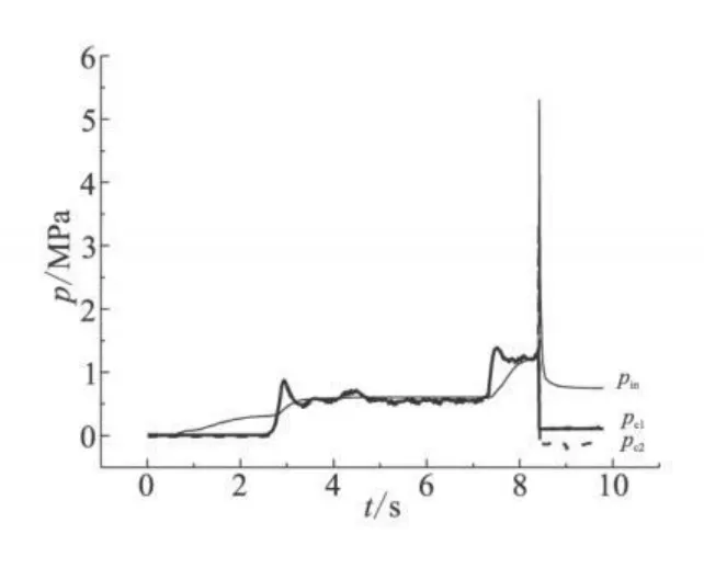
Fig.6 p-t curves of the firstmotor test
Table 1 shows that the peak of pc1,pc2,and pinappear respectively at 8.4 s,8.41 s,and 8.42 s,which means the pressure surge begins from the catalytic chamber and is influenced by the accumulation of H2O2in the catalytic chamber.

Table1 Test data of the firstmotor test
This accumulation ismainly attributed to the fact that the spray particle size of H2O2is not smallenough so that contacts between H2O2and catalytic network are not sufficient,therefore H2O2can't be fully and rapid ly catalyzed and decomposed.Meanwhile the burning of fuel results in a great deal of heats.The strong thermal feedback from the chamber led to the rapid decomposition of the accumulated H2O2in catalytic chamber.With the rapid ly increasing pressure in catalytic chamber,themotoreventual-ly exp lodes.The results of explosion is that screws connecting nozzle and the shellare cutoff,thewhole nozzle is thrown,the afterburner is partially defected,the LDPE grain is thrown from chamberwith a little deformation,the catalytic blanket is underm ined with deformed plate and concave network.
Based on the analysis of the explosion reason in the first test,the second testhas been donewith the following imp rovements:
(1)improving the quality of H2O2atomization and reducing the“channel effect” of catalytic oxidizer atomization network by replacing the DC-type nozzle with centrifugal nozzle;
(2)changing the front-end of grain into a step-type to form a partial back flow area,which plays the role of pre-chamber;
(3)augmenting the catalyst chamber exit and changing the test engine from horizontal to vertical to reduce the accumulation in catalyst chamber.
Fig.7 shows the p-t curves in the second test.Average pressure at the head of chamber is about 0.9 MPa.Test ignition delay is about 0.3 s.The pressure curve is stable,and no harmonic component appear in Fig.7 and Fig.8,which means the low frequency oscillation combustion problem of HRM was basically solved with the improvementmethod.

Fig.7 p-t curves of the second motor test
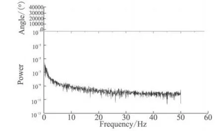
Fig.8 FFT ana lysis of p ressurs curves of the second motor test
According to the flow of water calibration coefficient,the H2O2instantaneous flowrate is calculated by pinand pc1,the results are shown in Fig.9.The overall H2O2flowrate is relatively stable,with some changes over time because of the slow declining ofgas tank pressure.
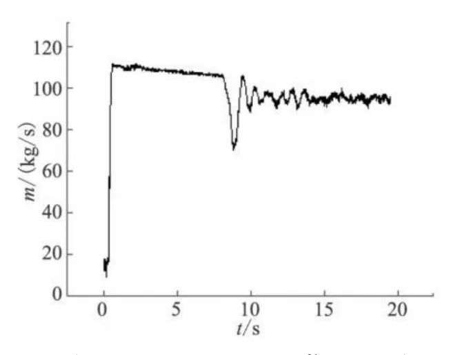
Fig.9 Instantaneous flow rate in the second motor test
The H2O2flow rate calculation formula:

where Cd,Ain,andρ0represent the water calibration coefficient,area of liquid nozzle and density of 85%H2O2respectively;Δp is the difference between the oxidantportal pressure and the pressure at thehead of combustion chamben,which can be calculated byΔp=pin-pc1.
The withdrawal thickness of PE fuel has been measured,and withdrawal rates in different parts of the grain have been calculated and is shown in Fig.10.

Fig.10 Field measurement of withdrawal rates in different parts of grain
The measurement results show that the withdrawal rate almost reaches its design value(0.3m/s),and is up to itsbiggestvalue at the head of chamber.This is due to the big heat transfer coefficient in the back flow area and the high burning temperature at the head of chamber.
4 Conclusions
The low frequency non-acoustic oscillation combustion in 85%H2O2-LDPE HRM ismain ly due to the cou-pling of oxidant supply system and the chamber.With the low frequency oscillation combustion,theworking stability of the HRM will decrease and its peformance be badly afffected,and even some other accidentsmight be caused.This study shows that the low frequency non-acoustic oscillation combustion can be effectively eliminated by adding a throttle plate in the oxidizer supply pipe,which can increase the rigidity of supply pipeline and improve the nozzle atomization effect.
Reference:
[1]Boardman T A,Brinton D H,Carpenter R L and Zoladz T F.An experimental investigation of pressure oscillations and their suppression in subscale hybrid rocket motors[R].AIAA 95-2689.
[2]Du Xin,Wang liang.Experimental study on hydrogen peroxide and polyethylene hybrid rocket motors[J].Journal of Solid Rocket Technology,2003,26(2):61-64.
[3]Du Xin,Wang liang.Research on low frequency unstable combustion of H2O2-PE hybrid rocketmotors[J].Journal of Solid Rocket Technology,2004,27(1):24-27.
