90 nm STIStress Simulation and Research Based on TCAD*
LIU Bingtao,SUN Lingling,LIU Jun
(Key Lab of RF Circuit and System,Ministry of Education,Hangzhou Dianzi University,Hangzhou 310018,China)
When the critical dimension of CMOS devices scales down into the submicron domain,the isolation technique of local oxidation of silicon(LOCOS)is not used anymore because of its bad scalability and severe bird'sbeak effect.Hence,LOCOShas been replaced by shallow trench isolation(STI)for its lower temperatures processing,which reduces the thermal budget,and good scalability as the critical dimension shrinks.But the STI causes compressive stress on the CMOS transistor that changes the device performance,especially with deep submicron dimension.During the cooling down process from the high temperature at trench fill,the STI compressive stress is resulted.And the different coefficients of thermal expansion(CTE)of silicon substrate and STIoxidemake a contribution to the compressive lateral stress between the oxide and the silicon in the active area of the transistor[1].
We can control themagnitude of the compressive stress along the channel by changing the active space(the distance between the channel edge and STI edge),which is introduced in BSIM3 and BSIM 4modelsas Sa and Sb[2].(see Fig.1)
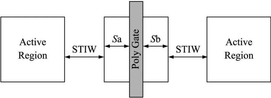
Fig.1 Top view of the CMOSstructure with variable active length,Sa=Sb.
Smaller Saor Sbmeanshigher STIstress,and the STI compressive stress makes NMOS performance change significantly.The degradation of the device characteristics main ly comes from the distorted silicon crystal,making the carrier mobility change via band scattering rates and carrier effectivemass.
The influence of the STIstress(both the x-stress and y-stress)has been investigated in a few works[3-6],and in this paper we report an extensive simulation of STIstress effecton differentactive lengths for 90nm technology nodes using TCAD process and device simulation.We show that stress is significantly increased when Sa decreases.
1 Device Simulation
The simulation tool thatwe used for simulation is Sentaurus TCAD,which can perform accurate process simulation and device simulation.
In this paper,our aim is to analyze themechanical STI stress effect on the transistor and set eight different active lengths(Sa=0.4,0.8,1.2,1.6,2.0,2.4,2.8,3.2μm).We fixed the transistorwidth to 1μm,so that the y-stress along the direction of gate width is negligible.And the source and drain in all the transistors are symmetric,that means Sa=Sb.The structure of the CMOS transistor is shown in Figure 2.During the 2 D process simulation,we analyzed the stress distribution along the channel transverse direction and compared the magnitudes of the STIstress in the channel region for different Sa.
After the process simulation,the device simulation is performed to calculate the saturation drain current,Idsatand the threshold voltages in the channel.
For CMOS 90nmmeasurement,the DC curvewas measured at Vd=1.2 V and Vb=Vs=Gnd.The simulated changes of Idsatfor different Sa are compared to experimental data from measured.The simulated data of different Sa are compared to measured data from IBM's 90 nm CMOS technology.
2 Results and Analysis

Fig.2 The simulated n-MOSFET structure.
In this paper,we analyzed the mechanical stress in device induced by STI in the channel direction,hence the Sxxstress is the main component of the stress tensor,that influences the carrier mobility.Figure 3 shows the x-stress distribution along the channel direction,the negative value indicates the stress is compressive.When the active length Sa=0.4μm,the value of the Sxxstress in the channel is-87 MPa and as the Sa increases,the stress is decreased to-33 MPa.
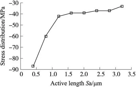
Fig.3 Simulated stress data in unit MPa,the value is taken from the center of the channelwith the different Sa.
Figure 4 shows the simulation results of 90 nm gate length and 1μm gate width NMOS Idsatversus Sa for eightdifferent Sa.When Sadecreases from 3.4μm to 0.4 μm,Idsatdecreases by 34.6 μA/μm,which is 7%degradation.This result agrees with themeasured data as showed in the Figure 6.
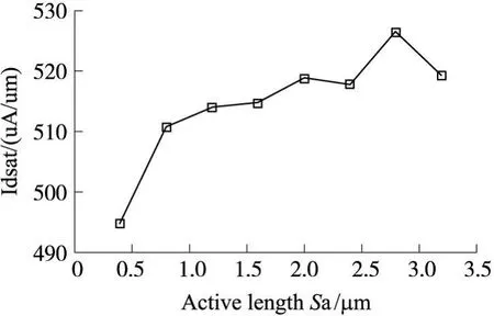
Fig.4 Simu lated data of NMOSW/L=1/0.09μm Idsat vs Sa.
From the figure 4we can see that Idsatdecreasesby 34.6 μA/μm when Sa decreases from 3.2 μm to 0.4μm.
Figure 5 shows the simulation result of the same device with Vthversus Sa for 8 different Sa.When Sa decreases from 3.2μm to 0.4μm,Vthof the NMOS increases by 18mV,which isan 8%change.This resultalso agreeswith the extracted data as showed in the figure 7.
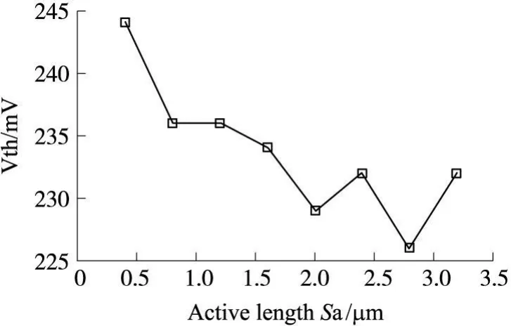
Fig.5 Simulated data of NMOSW/L=1/0.09Vth vs Sa.
From the figure 5 we can see that Vthincreases 18 mV when Sa decreases from 3.2μm to 0.4μm.
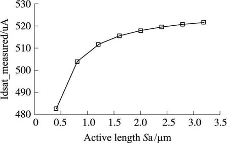
Fig.6 Measured data of NMOSW/L=1/0.09 Idsat vs Sa.
From the figure 6we can see that Idsatdecreases38.7 μA/μm when Sa decreases from 3.2 μm to 0.4 μm.

Fig.7 Extracted data of NMOSW/L=1/0.09Vth vs Sa.
From the figure 7 we can see that Vthincreases 21 mV when Sa decreases from 3.2 μm to 0.4 μm.
3 Conclusions
We have studied the dependence of the active length Sa and the STI stress,the compressive stress at the channel becomes larger when Sa decreases.The simulation results show that the compressive stress induced by STIsignificantly changes the NMOSFET characteristics.The large compressive stress causes the decreases of the electron mobility and the diffusion of the halo impurity(boron),so the Idsatis decreased by 7%and the Vthis increased by 8%.The simulation results agreewith the experimental data at 90nm CMOSnode.References:
[1]Rueda H A.Modeling of Mechanical Stress in Silicon Isolation Technology and Its Influence on Device Characteristics[D].University of Florida,1999.
[2]Xi X.BSIM 4.3.0MOSFETModelUser'sManual[S].University of California,Berkeley,2003:131-137.
[3]Miyamoto M,Ohta H,Kumagai Y,et a I.Impact of Reducing STI-Induced Stress on Layout Dependence ofMOSFET Characteristics[J].IEEE Transactions on Electron Device,2004,51(3).
[4]Su K,Sheu Y,Lin C,et al.A Scaleable Model for STIMechanical Stress Effecton LayoutDependence of MOSElectricalCharacteristics[C]//IEEE Custom Integrated Circuits Conference,2003:245-248.
[5]Tan P B Y,Kordesch A V,Sidek O.CMOS Shallow Trench Isolation x-Stress Effect on Channel Width for 130nm Technology[J].Solid-Stateand Integrated Circuit Technology,2006,6(8):478-480.
[6]P B Y Tan.Compact Modeling of Mechanical STI y-Stress Effect[J].Solid-Stateand Integrated Circuit Technology,2006,6(8):1450-1452.
[7]Sheu Y M,Doong K Y Y.Study on STIMechanical Stress-Induced Variations on Advanced CMOSFETs[C]//International Mi-croelectronic Test Structures Conference,2003:205-208.
[8]Sheu YM.ModelingMechanical Stress Effecton DopantDiffusion in Scaled MOSFETs[J].IEEE Transactionson Electron Devices,52(1):30-38.
[9]Kahng A B.Exploiting STIStress for Performance[C]//International Conference on Computer A ided Design,2007:83-90.
[10]Gallon C.Electrical Analysisof Mechanical Stress Induced by STI in Short MOSFETs Using Externally Applied Stress[J].IEEE Transactions on Electron Devices,2004,51(8):1254-1261.
[11]Tan P B Y.Hook Shaped Drain Current vs Width Curve of 130 nm CMOS Technology[C]//National Symposium of Microelectronic(NSM),2005,in press.
[12]Pacha C.Impact of STI-Induced Stress,Inverse Narrow Width Effect,and Statistical Vth Variations on Leakage Currents in 120 nm CMOS[C]//Solid-State Device Research Conference(ESSDERC),2004:397-400.
刘秉涛(1984-),男,汉族,山西汾阳人,现为杭州电子科技大学射频电路与系统教育部重点实验室硕士研究生,主要研究方向为器件模型,55fendout@163.com;

孙玲玲(1956-),女,汉族,浙江杭州市人,教授,博士生导师,主要研究方向为集成电路 CAD、RF集成电路设计及光电集成、集成电路应用系统设计。
——王永平教授
——陈桂蓉教授
