
Carrier Ethernet Services and Techno logies
2009-06-04 13:07MiZhengkun
ZTE Communications 2009年1期
Mi Zhengkun
(Nanjing University of Posts and Telecomm unications, Nanjing 210003, P. R. China)
Abstract:Carrier Ethernet(CE)services generally re fer to the standard ized carrier-c lass transfer services that feature in excellent sca lability,reliability,m anageability and Qua lity of Service(QoS)guarantee,and are o ffered by carriers to users based on Ethernet techno logies.One of the important characteristics of CE service is the d iversity of its imp lem entation technologies.Enhanced Ethernet technologies consider scalab ility as their chief ob jective so as to extend conventiona l Ethernet b ridge technolog ies;the latest Provider Backbone Bridge Tra ffic Engineering(PBB-TE)em erges as the technical trend o f CE technology.Mu lti-Protoco l Label Sw itch(MPLS)offers reliab le Pseudow ire(PW)connec tions for CE based on Labe l Sw itching Path(LSP).The convergence o f MPLS and PBB is one of the important evolution trends for CE.Making full use of the existing Op tical Transport Network(OTN)infrastruc ture,the op tica l ring network technology is the m ost cost-efficient and effec tive way to de liver CE services;its future developm ent trend is characterized by enhancing the Operation,Adm inistration and Maintenance(OAM)func tion and the control p lane.
A s a type of LocalArea Network(LAN)technologymostw idely used in com puternetworks,Ethernet technology features in easy-to-use,low costand excellent flexibility.Originally designed for LAN environment,Ethernet technology is oriented to enterp rise Intranetand thus is"enterp rise-c lass".Ethernet technology mustbe im p roved in terms ofsecurity,scalability and manageability for app lying in carriernetworks oriented to pub lic users.Aim ing atdelivering carrier-c lass Ethernetservices,the Metro Ethernet Forum(MEF),founded in 2001,p roposed amethod forusing enhanced Ethernet technologies in MAN and brought forward the concep tof metro Ethernet.In 2005,the MEF changed the name ofmetro Ethernetinto Carrier Ethernet(CE)to furtherspecify that it is a type ofEthernet technology used in carriernetworks.
The MEFhas defined CE as ubiquitous,standard ized,carrier-c lass networks and services w ith five technical features thatd istinguish CE from LAN-based Ethernet.CEmakes use ofEthernet's com pelling cost-effectiveness advantage to achieve significantbenefits,and enab les fast dep loymentofnew distributed app lications forenterp rises.AllCE Network Elements(NEs)mustpass certification tests so that they can serve users worldw ide.CE technology can also app ly to the Wide Area Network(WAN)though the concep twas originally p roposed forMAN.A lotof carriers are making such technicalattemp ts and trying to accumulate experience in this regard.
CE involves two aspects:Services and technologies.Oriented to users,the CE service p lane is independentofused technologies and is defined by the MEF.Oriented to networks,the CE technology p lane is p roposed by such standard ization organizations as IEEE,ITU-Tand IETF to p rovide defined CE services.Itshould be noted thatCE technology,instead ofbeing a specific network technology,ac tually refers to any technologies thatmeetMEF-defined CE technical features.Carriersmay op t fora specific type ofCE technology by taking into accountsuch factors as service requirements,network environment,dep loymentcostand existing facilities.
The five MEF-defined technical features ofCE are standard ized services,scalability,reliability,Quality ofService(QoS)and servicemanagement[1].
1 CE Services
1.1 CE Service Model
In the basic modelofCE services[2],shown in Figure 1,the Metro Ethernet Network(MEN)refers to the carrier network builtbased on Ethernet technologies(thatis,CE),and consists of MAN and backbone network.Like communication networks,the MEN also contains two types of interfaces:User Network Interface(UNI)and Network Network Interface(NNI).Userequipment accesses network through UNIusing 10Mb/s,100Mb/s,1Gb/s or10Gb/s Ethernetinterface,while carriers offerCE services to users through UNI.Different transport technologies are adop ted to supportCE services w ithin MEN,such as Synchronous Op ticalNetwork(SONET),DenseWaveleng th Division Multip lexing(DWDM),Multi-ProtocolLabelSw itch(MPLS)and Generic Fram ing Protocol(GFP).But from users'perspective,the network connection at the UNIuserside is sim p ly Ethernet.
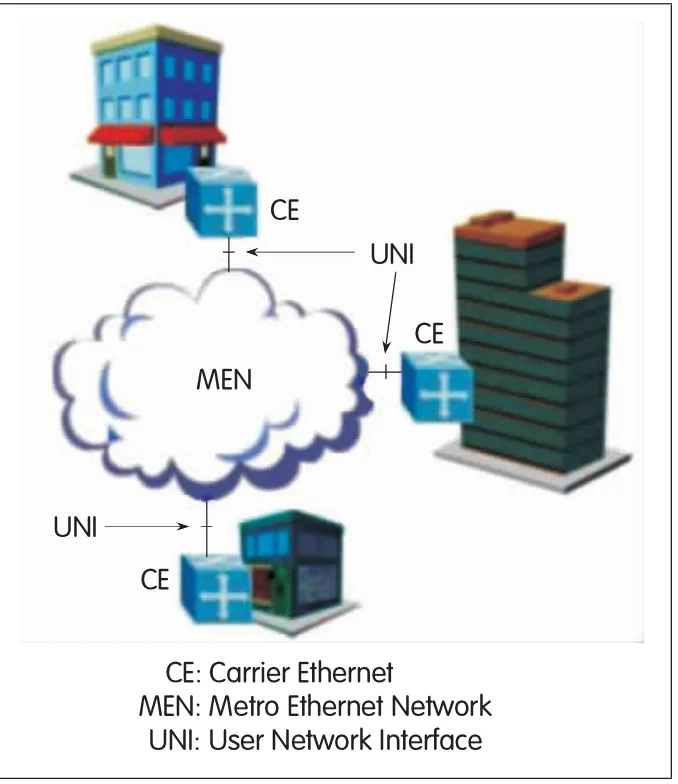
▲Figure 1. Basic model of CE services.
Like an IP network,CE is also a packetnetwork offering g lobal connections.The difference between them lies in the fact that IPnetwork offers g lobalconnec tions between any two hosts,while CE offers g lobalconnections forp redefined network interfaces so as to construc tmultip le ded icated Ethernets w ithin a w ide area,as shown in Figure 2.Therefore,a CE service is p rovided by setting up connections between specified UNIs,and these connections are known as EthernetVirtual Connections(EVCs),thatis,logical channels capab le ofstatistical multip lexing between UNIs,sim ilar to the Frame Relay(FR)and PermanentVirtual Connec tion(PVC)in Asynchronous TransferMode(ATM).
An EVC is used to connec tmultip le usersites(that is,UNIs)for transferring Ethernet frames among these sites and simultaneously b locking data communicationw ith the sites thatdo not belong to this EVC.The basic rule of frame transportis that the transferred service frame is not returned to the originating UNI,and the Med ia Access Control(MAC)add resses and the frame content remain unchanged during the transport.The CE service type is sub ject to d ifferentconnection configurations ofEVC.
1.2 Classification of CE Services
The MEFdefines three types ofCE services:E-Line,E-LAN and E-Tree.As the sim p lestbasic service type,E-Line corresponds to the point-to-point connection configuration ofEVC.Often known as p rivate line service,E-Line can be used to transferany packets defined by"Ethertype".E-LAN offers unicast,multicast,MAC add ress learning and IP packet transfer capabilities of LAN,and corresponds to the multipoint-to-multipointconnection configuration ofEVC.Itmakes fulluse of the inherent technical features of Ethernet to im p lementmulticast.As a sim p lified form ofE-LAN,E-TREE refers to a type ofservice in which data frames are sent from a specific source to alldestinations,and also corresponds to the point-to-multipointconnection configuration ofEVC.Typ icalE-Tree app lications inc lude video b roadcast to fam ily users aswellas Layer2(L2)isolation among users in the access network.Each of the abovementioned service types app lies to eitherUNIor certain VirtualLocalArea Network(VLAN)in UNI.Therefore,each service type can be furtherpartitioned into Private one and VirtualPrivate one,for exam p le,Ethernet-Private Line and Ethernet-VirtualPrivate Line services.
The MEF describes characteristics ofeach specific service using the"Type-Attribute-Parameter"mode and defines the follow ing nine attributes,each ofwhich contains severalparameters:
(1)Ethernetphysicalinterface:Physicalmed ia,rate,transfermode and MAC layer type;
(2)Bandw id th parameter:Comm itted rate and excess rate ofUNI/EVC/Class ofService(CoS);
(3)Performance parameters:Availability,frame delay,frame jitterand frame loss rate;
(4)CoS:Service c lasses c lassified based on d ifferent standards;
(5)Service frame transfer:Frame types allowed to be transferred and UNIs availab le;
(6)VLAN tag support:VLAN tag supportcapability and tag hand ling mode;
(7)Servicemultip lexing:UNI's supportofmultip le EVCs;
(8)Bind ing:Many-to-onemapp ing of VLAN ID to EVC;
(9)Security filter:Access filtering control.
Service instances are defined by the"Type-Attribute-Parameter"mode,and data frames ofeach service instance are transported through one EVC.
2 CE Technologies
The issue thatmustbe add ressed w ith firstp riority is the scalability ofCE technologies,that is,enab ling carrier networks to supporta large amountof co-existentCE service instances.For enterp rise users,a large-scale MAN needs to support tens of thousand EVCs,and hund reds of thousand EVCs across the WAN;for fam ily users,a large-scale MAN usually needs to supporthund reds of thousand orevenm illions EVCs.With regard to E-LAN services,a large-scale MAN needs to support tens of thousand oreven hund reds of thousand MAC add resses,and worldw ide across-WAN app lications should supporthund reds of thousand orevenm illions MAC add resses.Another importantissue is thatCEmusthave reliability and Operation,Adm inistration and Maintenance(OAM)capability,originally absent in legacy Ethernet.
To add ress the above issues,IEEE,IETFand ITU-Thave p roposed several CE solutions respectively based on Ethernet technologies,MPLS technologies and op tical transport technologies.These CE technologies can be generally c lassified into enhanced Ethernet,MPLS,and op tical ring network technologies.Furthermore,they have also p roposed the OAM technology forCE.

▲Figure 2. CE connections.
2.1 Enhanced Ethernet Technology
Proposed by IEEE,the enhanced Ethernet technology,based on VLAN technology,enhances Ethernet scalability by adop ting suchmethods as hierarchicalarchitecture and sim p lified b ridging,aim ing to be app lied in carrier networks.Its technicalevolution route is 802.1(legacy Ethernet)→802.1Q(VLAN)→802.1ad(PB,Q-in-Q)→802.1ah(PBB,MAC in MAC)→802.1Qay(PBB-TE).Figure 3 shows the frame formats correspond ing to various standards.
The legacy Ethernetused in LAN is a shared med ia,and itmainly uses b ridging technology to imp lement interconnection and data forward ing.The loop-freem inimum spanning tree connecting allb ridges is estab lished using the Spanning Tree Protocol(STP).The bridges estab lish forwarding tab les to allnodes through MAC add ress learning,and send unicastormulticast data frames to destination nodes along the spanning tree to acquire the zero-configuration"Plug and Play"capability.Such bridges are generally called transparentbridges.Figure 3(a)shows the frame formatof legacy Ethernet,in which data are transferred based on Customer Destination MAC Add ress(C-DA)and allend devices are interconnected through LAN to form a sing le broadcastdomain.
The concep tofVLAN[3]is introduced in 802.1Q to isolate differentuserg roups and ensure communication security.As shown in Figure 3(b),Customer VLAN Tag(C-Tag)is added into the frame formatby the source b ridge,containing Customer VLAN Identifier(C-VID).All b ridges are only allowed to transferdata frames to the ports thathave the same VLAN configuration and tag.In thisway,a physicalnetwork can be divided into severalmutually isolated b roadcast domains,and only end devices in the same VLAN can transferdata between each other.Furthermore,data frames only need to flood w ithin one VLAN while b ridges are conducting MAC add ress learning,which effectively reduces bandw id th consum p tion.This p rotocol aim s atmed ium-scale LANs,and therefore the length ofC-VID is defined as 12 bits,thatis,amaximum of4,096 VLANs can be defined.

▲Figure 3. Various Ethernet frame formats.
With the introduction of VLAN,carriers can offerCE services ford ifferentusers by using b ridges,forexamp le,offering LAN interconnection formultip le enterp rises,as long as they assign a d ifferentC-VID foreach CEuser.However,the C-VID settings are sub ject to users,and carriers have to coordinate the assigning ofC-VIDs to avoid conflicts,which definitely increases system operation com p lexity.To solve this p rob lem,the concep tofVLAN stacking[4]is introduced in 802.1ad,which adds a Service VLAN Tag(S-Tag)before C-Tag in the frame format.The S-Tag contains the Service VLAN Identifier(S-VID)used by the carrier network,as shown in Figure 3(c).Having two VLAN tags,VLAN stacking is also known as Q-in-Q,and related carrier networks are called Provider Bridge Networks(PBNs).The b ridges in a PBN transfer data frames based on the S-Tag thatcorrespondsw ith the CE service instance;C-Tag is notused and C-Tags ofd ifferentservice instances can be identical.The ingress edge b ridge adds an S-Tag into the frame when a data frame is injec ted into the PBN,and deletes the S-Tag before this frame is leaving PBN.
The VLAN stacking technology makes C-VIDs and S-VIDsmutually independent,butstill fails to add ress the scalability issue ofCE because the leng th ofS-VID is still12 bits,thatis,a maximum of4,096 service users are supported.The scalability issue lim its the service scale ofcarriernetworks and affects carriers'revenue.In add ition,although S-Tag is the unique ID ofa service instance,the PBN b ridge still needs to learn C-DA before data forward ing.The exceed ing ly large numberofend users also lim its the scalability of carriernetworks.In this situation,the hierarchicalarchitec ture of carriernetworks[5]is introduced in 802.1ah.Thatis,one layerofProvider Backbone Bridge Network(PBBN)is added above the PBN,and accord ing ly one Service Instance VLAN Tag(I-Tag)is added in the frame format,as shown in Figure 3(d).An I-Tag corresponds to a service instance in PBBN,and this I-Tag contains a 24-bitservice ID(I-SID),therefore,the PBBN can supporta maximum of16,000,000(224)CE service instances.Furthermore,three other fields of Backbone Destination MAC Add ress(B-DA),Backbone Source MAC Add ress(B-SA)and Backbone VLAN Tag(B-Tag)are added in add ition to I-Tag,inwhich B-DA and B-SA refer to the backbone MAC add resses ofeg ress and ing ress edge b ridges ofPBBN respectively.It is noteworthy that the backbone MAC add resses are assigned by carriers and are independentofuser MAC add resses.When a data frame is injected into a PBBN,the ing ress edge bridge determ ines and adds B-DA and B-SA into the frame,so the b ridges in PBBN only need to learn backbone MAC add resses instead ofuserMAC add resses before transferring data frames.The lim ited numberofedge b ridges add resses the scalability issue ofMAC add ress learning.B-Tag is a valid VLAN ID in PBBN and is 12 bits in leng th.It is used to further d ivide PBBN into severalbroadcastdomains to imp rove bandw id th utilization efficiency and realize PBBN load sharing.The ing ress edge bridge of PBBN first learns the C-DA and C-SA ofdata frames to determ ine B-DA and B-SA,then obtains I-Tag based on C-Tag/S-Tagmapp ing,and finally binds I-Tag to B-Tag.The PBBN b ridges then transferdata based on B-DA and B-Tag.802.1ah is also known as MAC in MAC because there are two-layerMAC add resses in the frame format.PBBN ac tually supports multi-layerMAC add ress,so itcan add resses the scalability issue ofCE.
The abovementioned PBB technologies solve the p rob lem ofCE scalability,butdata forwarding is stillin the connec tionlessmode.To enhance QoS performance,IEEEmade a few revisions of802.1ah,and p roposed the Provider Backbone Bridge Traffic Engineering(PBB-TE)technology,that is,802.1Qay standard[6].802.1Qay reserves the MAC in MAC frame format,butd isab les Ethernetspanning tree and MAC add ress learning functions.It estab lishes connection-oriented tunnels fordata forward ing,and enhances certain carrier-c lass OAM func tions.Therefore,PBB-TE enab les hard QoS sim ilar to the reliability and manageability ofSDH technology,and offers ded icated Ethernet links w ith carrier-c lass performance;it transform s the connectionless Ethernetinto a connection-oriented network and fulfills end-to-end service p rovisioning and management in Ethernet.
PBB-TE data forwarding no longer hinges on the conventional flood ing and learning scheme;instead,it is directly p rovided by the networkmanagementor controlp lane.This elim inates the b roadcasting function ofunknown add ress flooding so as to further enhance network scalability.In add ition,a large amountof the physical-or network-layernetworkmanagement functions defined by IEEE and ITU are m igrated to the data link layer to enab le hard QoSw ithoutover-p rovisioning of link capacity,achieving SDH-alike carrier-c lass networkmanagement functionality ofbandw id th reservation and p rotection sw itching in 50m s.Furthermore,as a type of L2 tunneling technology,PBB-TE can interworkw ith existing WAN technologies,and support various Ethernetservices aswellas MPLS-based services inc lud ing L2 VirtualPrivate LAN Service(VPLS)and Pseudow ire(PW)services and Layer3(L3)VirtualPrivate Network(VPN)services.In p racticaldep loyment,PBB and PBB-TE technologies can be combined through B-Tag partition resulting in partVLANs in PBBN using PBB and the others using PBB-TE.
PBB-TE technologies availab le fulfill connection-oriented data forward ing by adop ting static p re-configuration scheme.The inc rease ofnetwork scale may bring about the N-square p rob lem,so the IETF is working towards the introduc tion ofGeneralized Multi-ProtocolLabelSw itching(G-MPLS)as the controlp lane.
2.2 MPLS Technology
A significant technicalfeature ofMPLS is its supportof the combination of connectionless and connection-oriented technologies.Itcan notonly estab lish and maintain IP packet transportpaths by adop ting L3 routing p rotocols,but also re-use various L2 sw itching technologies such as frame relay,ATM and Ethernet to realize fastpacket forwarding.Over the pastdecade,the g lobaltelecom industry hasmade a huge investment in c reatingmore developed and mature MPLS technologies to p rovide both carrier-c lass QoS and excellentscalability.MPLS has become a g lobally recognized mainstream transport technology of the core network.Itsupports a lotof functions absent in Ethernet,inc lud ing large-scale network routing,resource reservation,VPN,Traffic Engineering(TE)and across-area and across-operation-domain networking.Itw illtake a coup le ofyears for Ethernet to reach the same technical maturity as MPLS.Therefore,itis not feasib le for the above Ethernetbridge technologies(inc luding PBB),the effective transportsolution foraccess networks and MANs,to rep lace MPLS,a core network transport technology app licab le in a w iderarea.Instead,they are com p lementary to im p lement end-to-end transportofdata frames in the w ide area.
As faras CE technologies are concerned,the MPLS technologies involved inc lude VPLS,Hierarchical VPLS(H-VPLS)and TransportMPLS(T-MPLS)technologies.
As a technicalstandard p roposed by the IETF,VPLS[7]constructs virtual Ethernetby using L2 VPN ofMPLS and connec tsmultip le sites at the network edge.VPLS is an extension of point-to-point L2VPN VirtualPrivate Wire Service(VPWS).VPLS can be deemed as a logicalb ridge broadcast domain consisting ofa group ofVirtual Sw itching Instances(VSIs).Sim ilar to the b ridge function defined in 802.1Q,each VSIforwards data frames based on the destination MAC add ress and L2 VPN member ID,and floods unknown add ress frames,broadcast frames and multicast frames to allports of the VSI.
As an extension of VPLS,H-VPLS aim s atim p roving the scalability of VPLS.H-VPLS b reaks down an MPLSnetwork into a core network and severalaccess domains interconnected through the core network.The edge equipmentof the core network is called Network Provider Edge Equipment(nPE),and the edge equipmentofaccess domain and user interfaces is called User-Facing Provider Edge Equipment(uPE).uPEonly learns localnPE,and connec ts w ith localnPE through PWs.There is fullymeshed VPLS connec tivity only among nPEs of the core network.The core MPLS network can be furtherd ivided into severalVPLS subnets fullymeshed through PWs,so as to effectively reduce network comp lexity and multicastoverhead.
Itis a cost-effec tive CE solution w ith good performance to combine Ethernet bridge technology w ith H-VPLS.In this case,802.1Q,802.1ad or802.1ah can be adop ted in the access domain.
Defined by the ITU-TSG15,T-MPLS is a connec tion-oriented packet transportMPLS-based technology used to p rovidemanageab le point-to-point L2 connec tion forvarious service networks[8].MPLS and T-MPLS have identicallabelstructure aswellas label sw itching and forward ing mechanism.ButTMPLS abandons the connectionless transportmode,removes unnecessary IP-based connectionless forward ing p rocesses and allL3 functions,and sim p lifies the controlp lane to lower network construction and maintenance costs.On the otherhand,T-MPLS adds end-to-end OAM and performance monitoring func tions.Bid irectional symmetric LSPs are set for T-MPLS to remain consistentw ith communication networks.Sim ilar to SDH paths,bid irectionalsymmetric LSPs feature in long-term stability,and support p rotection sw itching and OAM mechanism s.Linearand ring p rotec tion standards have been defined by ITU to ensure excellentnetwork operation and maintenance and p rotection recovery capability.Sim ilar to PBB-TE,T-MPLS currently adop ts the p re-configuration based servicemanagementmode and willintroduce G-MPLSas the control p lane in the future.
To a large extent,the architecture of existing circuitsw itched networks is an im portant reference for T-MPLS standard ization.T-MPLS system has sim ilar structure and sim ilarmanagement and operationmodelw ith the circuit sw itched network,which facilitates carriers to fulfillsmooth evolution ofMAN and access network from circuit sw itching to packetsw itching.In term s of technology,T-MPLSenhances transport performance by adop ting the connection-oriented mode,lowers costs by sim p lifying p rotocols and functions,and fulfillsmanageability and reliability by enhancing OAMmechanism.In terms ofservice,T-MPLS supports packet transportin various service networks,inc lud ing reliab le transportof Ethernet data frames.Therefore,T-MPLS is also one of the significantCE technologies.
2.3 Optical Ring Network Technology
Enhanced L2 Ethernet technology,rep resented by PBB/PBB-TE,is an im portant technological foundation ofCE.Its combination w ith MPLS technology is the future development trend ofCE,while a variety ofapp licab le op ticaltransport technologies are used for the physical transportof Ethernetdata frames.Based on the live transportnetworks,various SDH-based op tical ring network technologies are stillim portant transport app roaches forCE on accountof operating costand reliability.
The fundamentalop ticalring network technology is to transportEthernetdata frames overan existing SDH transport system,and mainly inc ludes two access and encapsulation technologies.Accord ing to the Link Access Protocol for SDH(LAPS)[9]p roposed by China,Ethernetdata frames are d irectly encapsulated in SDH packets using High-LevelData Link Control(HDLC)encapsulation.The specific app lication modelof LAPS is described as follows:
(1)Configure an Ethernet interface in the SDH system.
(2)Configure a Synchronous TransportModule Level-N(STM-N)interface on the Ethernetsw itch.
(3)InstallEthernetOver SDH(EOS)transferequipmentbetween the SDH system and Ethernetsw itch.
The other technology is the Generic Fram ing Protocol(GFP)[10]developed by European and American vendors.Itcan encapsulatemultip le types of frames and transport them through d iversified op tical transport technologies.The specific app licationmodelofGFP is to deliver Ethernetservices on Multi-Service TransportPlatform s(MSTPs).
ResilientPacketRing(RPR)is a highly efficientop tical transport technology[11],w ith the following advantages:(1)RPR can send service data d irectly into the physical-layer frames or bare fibers through the new-added MAC layer.In RPR,non-landing packets can be d irectly forwarded,thereby significantly imp roving sw itching capability.Hence,this is the best possib le op tion for packetservices.Besides,RPR also supports Time Division Multip lexing(TDM)services.
(2)RPR supports automatic topology d iscovery,and guarantees p rotection sw itching in 50m s,thus ensuring the QoSofcircuit-sw itched services and dedicated line services.
(3)RPR supports two-fiber bidirectionalring topology.In both d irections of the ring,RPR enab les dynam ic statisticalmultip lexing for various services.In this way,the fiber bandw id th is utilized to fulldegree and network configuration and operation is sim p lified.
(4)In terms ofcost,RPR stands in between SDH and GigabitEthernet technologies.Hence,RPR ismost suitab le for the access layerofMAN,especially forapp lications inwhich bandw id th demand from Ethernet services takes absolute p recedence.
RPR also has a few disadvantages.RPR only supports ring networking and falls shortofc ross-ring standards.Moreover,ithas only one-layerMAC add ress forward ing,and does not p rovide hierarchicaladd ress structure and useradd ress isolation.Therefore,network and service scalability is somewhat lim ited.
The Multi-Service Ring(MSR)put forward by China is also a bid irec tional symmetric two-fiber ring[12].Inheriting the technologicaladvantages ofRPR,MSR defines a new L2 redundancy p rotocol,which can be deemed as an op tim ized version of the RPRMAC layer.Accord ing to this p rotocol,each node can add/d rop tributary signals.In add ition,more carrier-c lass features are added to the p rotocol.The MSR design aims to build new or reconstructcarriernetworks ata relatively low cost,and estab lish a Carrier EthernetMulti-Service Platform(CESP).MSR is supposed to supportsuch services as Ethernet,GigabitEthernet,DigitalVideo Broadcasting(DVB),ATM,and PacketOver SDH(POS),and also supportpacket forward ing as routers.With QoS guaranteed,MSR can support integrated transportofd ifferent formats of data,voice and video servicesw ith lower costs.In this way,MSRworks as a ring formed bymulti-service add/d rop multip lexers.MSR can be app lied to ring,link and star topologies,and italso supports in-service p lug-in/p lug-out,changeover,and upg rade functions.
MSR integ rates data transportand exchange,and supportsmulti-service point-to-point,multicastand b roadcast app lications.Moreover,itsolves the p rob lem of transportofCE services and TDM tributaries,and imp lements the transport,p rotection,multicastand performancemonitoring ofmultip le Ethernets and TDMs on RPR.Hence,itis an im portant technology regard ing CE.
In recentyears,the telecom industry started the research on the Ethernet ring,which features in lower costs and better compatibility compared to RPR.In particular,the EthernetAutomatic Protection Sw itching(EAPS)technology is a new cost-effective CE solution[13].Aim ing at the Ethernet ring topology,EAPS p rovides a sim p le and feasib le p rotectionmethod against line fault to realize the automatic p rotec tion of the Ethernet ring.In EAPS,Q-in-Q encapsulation is adop ted tomeet the CE requirements,butnodes stilluse standard Ethernethardware,so only software upgrade is required.In EAPS,there are two faultdetectionmodes:alarm mode(fastmode)and ring polling mode(packetdetec tionmode).The ring p rotection sw itching period is less than 1 s,and usually less than 50ms,so the Ethernet ring is almostas reliab le as the SDH ring.
EAPS features in low technological costs and excellentcom patibility w ith legacy Ethernets,so itis suitab le for the services w ith smalltraffic and fixed direction,forexam p le,enterp rise VPN and Softsw itch services.
However,EAPS also has disadvantages.Itonly supports ring networking,so it lacks flexibility.Moreover,ithas large frame loss ratio and lim ited scalability ow ing tomultip le data forwarding hops to a remote node.
2.4 OAM Technology
Ethernetcan transportdata atdifferent transport layers,and also has diversified customer layers.Neither the OAM func tion of the bottom layer(forexam p le,SDH)nor thatof the upper layer(for examp le,IP)ofnon-Ethernetcan rep lace the OAM function of Ethernet.
Crucial forCE,Ethernet layersmust be p rovided w ith an OAMmechanism com p letely independentof the customer layerand the service layer to achieve the follow ing ob jects:
·To determ ine the connectivity of EVC at the Ethernet layer.
·To effec tively detectand locate network faults originating from the Ethernet layer.
·Tomeasure the network resource utilization and network performance.
·To p rovide satisfactory services for users according to the Service Level Ag reement(SLA).
Through jointefforts,IEEE,ITU-Tand MEFwork outEthernetOAM standards,among which IEEE 802.1ag[14]and ITU-T Y.1731[15]aremature.These Ethernet OAM standards introduce the concep tof hierarchicalmaintenance domains into Ethernet.Amaximum of8 levels of maintenance domains can be d ivided,and respectively and independently maintained by customers,network carriers and service p roviders,but they have identicalOAM mechanism.EthernetOAM has two func tions:Fault managementand performance monitoring.Faultmanagement refers to the detection,verification,location and notification ofvarious faults.Performance monitoring refers to themeasurementof such performance as frame loss,delay and jitter.The IEEE standardsmainly define the faultmanagement,inc lud ing connectivity check,loop-back test,link-trace and remote defec tion ind ication.Besides,The ITU-T standards definemany otherOAM functions,inc lud ing the alarm ind ication signal,lock signal,testsignal,automatic p rotec tion sw itching,maintenance communication channel,frame loss test,frame delay testand throughput test.
3 Development Trend of CE
The further research on CEmay contain:
(1)Scalability,inc lud ing the scalability im p rovementofMPLS technology,802.1ah imp rovement,VPLS/802.1ah interconnec tion,and system software/hardware scalability im p rovement;
(2)Standards and technologies for carrier-c lass QoS guarantee,inc lud ing QoS,OAM,high availability,TE,and fast rerouting;
(3)Networkmanagementsystem and controlp lane,forwhich IETFand IEEE are working on new uniform controlp lane technologies to rep lace the conventional EthernetSTPmechanism,and one possib le op tion is to use GMPLS as the foundation ofcontrolp lane signaling;
(4)Analysis on Cap italExpenditure(CAPEX)and Operating Expend iture(OPEX)tomaintain the simp licity and cost-effectiveness ofCEw ith increasing new functions;
(5)Offeringmore fast-configurab le,flexib le and reliab le services based on userdemands,apart from existing E-Line,E-LAN and E-Tree services.
For carriers,the key is to decide on the op timalsolution from numerous existing CE technologies to adap t their specific situation,by taking accountof such factors as costs(CAPEXand OPEX),scenarios(building a new network orexpanding existing one),existing network technologies,maintenance personnelexperience,required services,technologicalmaturity,ease ofoperation,and p referred managementmode,among others.

- ZTE Communications的其它文章
- IMS for Enterprise Applications
- OAM Techno logy o f Packet Transport Netw ork
- Technology Development and Deployment Strategy of Carrier Ethernet
- Location-Based Routing Algorithm s for Wireless Sensor Netw ork
- Parallel Processing Design for LTE PUSCH Demodulation and Decoding Based on Multi-Core Processor
- Cooperative Comm unication and Cognitive Radio (1)