
On the effect of pitch and yaw angles in oblique impacts of smallcaliber projectiles
2024-02-29 08:21:52TeresaFras
Defence Technology 2024年1期
Teresa Fras
French-German Research Institute of Saint-Louis (ISL), Saint-Louis, France
Keywords: Ballistic impact Small-caliber projectile Pitch and yaw impact angles Shadowgraphy IMPETUS Afea Numerical simulations
ABSTRACT A terminal ballistic analysis of the effects of 7.62 mm × 51 AP P80 rounds on inclined high-strength armor steel plates is the focus of the presented study.The findings of an instrumented ballistic testing combined with 3D advanced numerical simulations performed using the IMPETUS Afea® software yielded the conclusions.The experimental verification proved that slight differences in the pitch-andyaw angles of a projectile upon an impact caused different damage types to the projectile’s core.The residual velocities predicted numerically were close to the experimental values and the calculated core deviations were in satisfactory agreement with the experimental results.An extended matrix of the core deviation angles with combinations of pitch-and-yaw upon impact angles was subsequently built on the basis of the numerical study.The presented experimental and numerical investigation examined thoroughly the influence of the initial pitch and yaw angles on the after-perforation projectile’s performance.
1.Introduction
The projectile’s terminal ballistic performance depends on a number of variables.Firstly, the projectile’s and targets’ compositions and geometries.Further, the target’s orientation and the initial impact kinematics-the projectile’s velocity and the projectile’s position upon an impact.The target is typically stationary during a terminal ballistics experiment, especially when tested against a small-caliber ammunition-its orientation can be easily controlled.With an established accuracy, light-detection barriers are used to measure the projectile’s velocity.It is more difficult,however,to measure accurately the orientation of the bullet at the moment of impact.
Projectiles are initially spun about their rotational axis by grooves inside the gun barrel to stabilize them during their flight.The spinning mass creates gyroscopic forces that keep the projectile length axis resistant to the destabilizing overturning torque[1].Most of the time, the projectile is somewhat unbalanced as these forces readjust the bullet position.In consequence,at the moment of the impact the projectile is typically not perfectly aligned with the vector of its velocity along the trajectory defined by the movement of the projectile’s center of gravity.The projectile orientation is described by two angles representing a misalignment with the projectile trajectory-pitch and yaw angle,and also its spin(roll).The principles of behavior of yawing projectiles are presented in the classical works of Goldsmith(for example[2,3]),in which the subsequent phases of blunt cylinder impacts into a perpendicular target plate are analyzed and 2 modeled with an influence of the initial yaw angles.Because of the oblique entry position, the striker’s deformation was affected by anon-symmetric stress distribution which increased due to additional angular changes of its movement.In consequence,the projectile underwent bending that resulted in its fracture.Despite a proven influence of the initial projectile position with respect to the target,in the literature in the most of analyzed terminal ballistic experiments,the information on the initial yaw and pitch angles of the projectile is rarely reported.This data becomeseven more important when the projectile hits the target inclined to the shot.In oblique impacts,the asymmetric interactions between the projectile and the oblique target become even more pronounced and the resulted angular momentum affecting the projectile core increases too [4].
On the contrary to studies on the normal impacts,there are not many open access studies which investigate oblique shots.Furthermore, it is the behavior of the target plates or the mechanisms of penetration and perforation, which are the main focus of such investigations.Normal and oblique impacts on 20 mm thick AA6082-T4 aluminum plates are analyzed both experimentally and numerically in the study[5].Two types of small arms bullets were used in the ballistic tests,the 7.62 mm×63 NATO Ball(with a soft lead core)and the 7.62 mm×63 APM2(with a hard steel core).The targets were struck at 0°, 15°, 30°, 45°and 60°, with an overall impact velocity 830 m/s.The key interest was the critical oblique angle at which the penetration process changes from perforation to embedment or ricochet.While the information on the materials composing the projectile was primarily sourced from the literature,a material test program was carried out for the AA6082-T4 plate in order to calibrate a modified Johnson-Cook constitutive relation and the Cockcroft-Latham failure criterion.The 3D non-linear FE simulations were performed and succeeded to obtain results of good agreement with the experimental observations.With the aim of determining the effects of the angle of obliquity, the study [6]examined the ballistic performance of monolithic, multi-layered and spaced mild steel target plates (of thickness varied between 4 mm and 16 mm)at normal and oblique impacts(0°,30°,45°and 60°) of 7.62 mm AP bullets.For 60°angle of obliquity, the monolithic target experienced a projectile ricochet, in contact layered target-a projectile embedment,and for the spaced target,it was a perforation.At low angles of obliquity, the difference between the ballistic performance of monolithic, layered in contact and spaced targets was not significant.The numerical simulations used the Johnson-Cook elasto-viscoplastic material model calibrated for the mild steel with which the targets were composed.The employed approach provided results corroborating the experimental findings.In the study[7],a series of oblique ballistic experiments with x-ray monitoring was carried out to study the effect of obliquity angle and armor steel plate thickness on the fragmentation of 14.5 mm API projectiles.According to X-ray records of the oblique impact experiments, fragmentation patterns of the core were found to be dependent on both the angle of obliquity and the thickness of the steel armor plate.Through a simplified fracture modeling implemented in the numerical simulation, all the traits of the core fragmentation were not captured but a reasonable agreement between the experimental and simulated results was obtained.The pitch and yaw angles of the projectile were not addressed in any of the aforementioned works.Since these experimental features were not verified, also in the simulations, the bullets were assumed as impacting perfectly straight.
Usually,both in numerical and in-field experimental studies the effect of the pitch and yaw angles,as well as of the projectile’s spin upon an impact are not subjected to in-situ measurements.Experimental measurements of the bullets orientation are challenging(especially for small-and medium-caliber projectiles,since artillery-or mortar projectiles and missiles may have an on-board instrumentation).Possible techniques which may be used to identify the projectile position before an impact are yaw cards(several paper sheets located along the projectile trajectory),highspeed cameras, radiography and shadowgraphs, [8].However, not all laboratories are outfitted with this kind of equipment.The NATO Standard AEP-55 [9] explains that for an evaluation of the protection level of armor components, all shots with a total pitch angle below 5°are considered as valid.It is quite unlike that a misalignment higher than 5°would occur in a professional terminal ballistic laboratory.On the other hand,when a numerical model takes into account the pitch and yaw angles of the projectile impact in addition to the target’s obliquity, this creates calculation challenges and increases the computation costs.However, precise values of the pitch and yaw angles prior to the moment of contact are crucial for further in-depth research inquiries on the projectile/target interactions.Armors and protection systems frequently use a combination of materials with various geometrical and material characteristics.A line of sight (LOS) of an armor is designed typically to extend the way during which a projectile traverses a protective shield,which favors obliquely assigned armoring.Although perfectly perpendicular strikes may be of the highest piercing potential, on the battlefield they are less common than slanted impacts.
The objective of the hereby presented experimental-numerical inquiry is to analyze how an armor-piercing hard-core bullet behaves after penetrating an armor steel plate inclined at 10°NATO.The initial impact conditions(i.e.projectile’s velocity,pitch and yaw angles) were experimentally measured and the study emphasizes effects of these traits on the projectile’s post-perforation characteristics (i.e.the projectile’s residual velocity, core damage, and angle of deviation).The armor-piercing(AP)7.62 mm×51 FMJ/PB/HC AP P80(0.308 Win)(fullmetal jacket,pointed bullet,hard steel core) projectiles and the 4.5 mm thick Armox 500T armor steel plates made up the impact arrangement.The undertaken measurements in the performed terminal ballistics experiments included flash X-rays imaging, digital high-speed cameras recording, due to which the initial and residual conditions of the impacts were registered.

Fig.1.Experimental stand: (1) laboratory gun; (2) velocity light-barriers; (3) pitch and yaw angle measurement set-up; (4) spall-protecting screens; (5) high-speed camera; (6)target inside the supporting frame.
The impact configuration’s components maybe considered as illustrative, but they are also included in the IMPETUS Afea® numerical software’s commercial library.The pre-defined components in the calculation software were used to prepare the numerical study in terms of their geometry and material modeling.Therefore, the ballistic experimental investigation was compared with its numerical representation not affected by a user way of preparation of the geometrical model, meshing and last but not least,constitutive functions of the materials composing the threat/target configuration.The subsequent sections report on the findings of the experimental, terminal ballistics investigation and confront them with the numerical results.The proposed approach intends to contribute to a still valid query-to which extent a numerical simulation is able to represent an experimental testing(which is also a laboratory rendition of battle-field possible impact scenarios).
2.Terminal ballistics testing
The objective of the study was to conduct an experiment verification of a variance in measured initial yaw and pitch angles of small-caliber projectiles upon impacts.As it was mentioned previously, the NATO Standard [9] accepts results of which the total yaw angle is below 5°.There are many alternative pairs of yaw and pitch angles that meet this requirement,therefore it’s interesting to see how the values permitted by the standardized ballistic procedure affect the behavior of projectiles.The experimental configuration composed with the 4.5 mm thick Armox 500T steel plates were aligned at 10°NATO to shots of the projectiles of caliber 7.62 mm × 51 AP P80.
Fig.1 depicts the experimental set-up,presenting a lab-adapted cannon placed 10 m in front of the testing stand equipped with the measurement devices.The gun consisted of a universal block with changeable barrels fixed to the recoil absorber mount.The gun barrel of a heavy profile had a length of 900 mm.The weapon was firmly fixed to the ground, which created astable platform preventing gun jerking.Shots were fired remotely.The primed cases were standard P80 cartridges filled with the original factorysupplied powder load, which amount was not changed.The hereby analyzed shots were performed one after another, using the projectiles taken directly from a factory box-as the amount of the powder in the cartridges was not changed,the measured velocities of impacts varied.
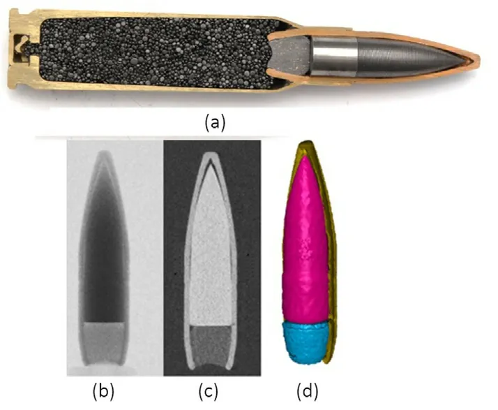
Fig.2.Projectile cal.7.62 mm×51 AP P80:(a)Cross-section;(b)Radiographic and(c)topographic slice and (d) surface-rendering of segmented components.
As the threat,the 7.62 mm×51 FMJ/PB/HC AP P80(0.308 Win)projectiles were chosen.Fig.2 presents the cross-section of the used projectile inside the cartridge filled with a powder.The projectile consists of brass jacket, lead cap filing and the hard-steel core.Following the requirements of the standard VPAM APR 2006[10],this particular caliber is used to evaluate the protection level 9 if it is shot at the impact velocity 820 ± 10 m/s from a distance of 10 m.The impact energy transmitted to the shot body exceeds 3200 J.
As the targets,the 4.5 mm thick Armox 500T steel plates of the size 250 mm × 250 mm were used.This armour steel has the nominal hardness of 500 HBW and its other properties, following the producer datasheet [11], are collected in Table 1.Fig.3(a) presents the plate of Armox 500T prepared for the ballistic impact test.The target plates were inclined at the angle of 10°(following the NATO requirements, Fig.3(b)).Each plate was shot 2 times, a distance of min.60 mm was kept between the shot points and the plate edge.Before each shot, it was verified if the plate was still inclined at 10°.
During the tests, these projectile’s kinetics were measured:
· Initial impact velocity (by the optical light gates)
· Yaw and pitch impact angles (by the optical light gates), Fig.4
· Residual velocities(based on the high-speed camera recording)
· Based on a previous investigation, the initial spin of the projectile was assumed as equal 21050 rad/s.
The measurements of the initial projectile characteristics were undertaken by the PROTYPA measurement system.From the side,each shot was recorded using a high-speed camera Phantom.Its resolution was 640 × 256 pixels, frame rate: 41000 fps, time exposure:300 ns,lens:100 mm,opening:level 2,flash occurred at 10 ns.
2.1.Pitch and yaw angle measurements
As a result of the projectile’s spinning motion after leaving the grooved gun barrel, the direction of its velocity vector typically differs from that of its longitudinal axis[12-14].An orientation of a projectile is thus defined by three rotations about the principal axes passing through its center of mass [2].The three fundamental angular motions of the striker are described by yaw and pitch angles, and the spin/roll.The spinning occurs about the projectile’s axis of symmetry and the yawing angles are defined in terms of the striker centerline to its velocity vector.For a better mnemonic visualization, the pitch angle may be schematically described by the head movement of "nodding", whereas yawing by the head"European no-shaking" [15].
In terms of the terminal ballistics investigations, the Standard[9] gives the definition of the horizontal, vertical and compound yaw angles.Thus, as the yaw angle the Standard defines the maximum resultant angle between the main axis of the projectile and its trajectory (velocity vector) irrespective of plane [9].As the angle of impact, the Standard describes the angle between the projectile trajectory and the direction perpendicular to the plane tangent to the point of impact on the target [9].These definitions are respected(though,the yaw angles have other designations)by both the calculation code IMPETUS [16] and the measurement device PROTOTYPA[17],Fig.4.In Fig.5,there are presented the yaw angles following their designation in the NATO Standard AEP-55.
The total yaw angle is calculated following the definition given in the report[18].The total yaw angle yt of a projectile is the angle between the vector of velocity of the projectile and the vector of its axis of symmetry in the plane defined by those two vectors.Thesymmetry axis can be aligned with the velocity by moving down through the pitch angle a and across through theyawangle β.

Table 1Properties of the ARMOX 500T steel according to the producer’s datasheet.

Fig.3.The plate of Armox 500 in the supporting frame prepared for testing: (a) Front view; (b) Side view; (c) Schematic description of the NATO angles designation.
Following Fig.5 and the considerations presented in Ref.[18],these angles are related to the total yaw angle through the dependences given by Eqs.(1)-(3).
Consequently, the total yaw angle γtis given by Eq.(4).
To measure the bullet velocity, as well as the yaw and pitch angles before the impact,the optical light gates were used.The light gates(LS-01L by PROTOTYPA)consisted of two light screens(gates)placed along a distance of 1 m between the gates(measuring base)perpendicularly to the bullet longitudinal axis.NATO STANARD AEP-55 [9] recommends measurement plane located perpendicularly to the projectile trajectory at a maximum distance of 2.5 m ahead of the aim point on the target.For the tests, the entry gate was located 1.5 min front of the target.An interruption of the light beam, caused by the bullet passage through, was caught by an electronic sensor and transferred to an electrical pulse.The velocity was determined from a time measured between the first and the second gate pulses [17].The measurements of the initial velocity are performed with the accuracy of 0.5% and the resolution of 0.1 m/s.
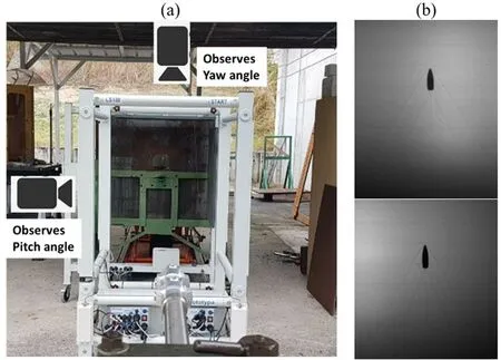
Fig.4.(a) The optical light gates and (b) the position of a projectile capture by it presented in the shadowgraphs of two planes.
Further, a pair of orthogonal cameras and flash-lights allowing acquisition of bullet images and evaluation of bullet yaw before impact on the target were used(PYAWMS by PROTOTYPA[17]).The system measured yaw and pitch angles relative to a reference line,Fig.4.A heavy and stable mounting system for the target plates was adopted in order to prevent the sample montage from influencing the experimental outcomes.The yaw measurements in close proximity to the tested target are not possible due to the design of the PROTOYPA setup.Additionally, the equipment needed to be shielded from potential spalls.Therefore, pitch/yaw angles measurements were taken 300 mm in front of the target (NATO STANARD AEP-55 does not precise an exact measurements method,neither a distance of the measures from a shot target).The angles are measured with the accuracy of ±0.005°[17].The calibration method is based on the comparison of yaw angles measured by the calibrated instrument PYAWMS andyaw angles of a reference calibration jig.Although,the measurements were taken in a certain distance from the target and the precise values of yaw and pitch angles of the projectile at an impact instant are unknown,it may be assumed that this interval is sufficiently short that the bullet orientation did not change significantly.
2.2.Experimental results

Fig.5.Definition of yaw and pitch angles following the Standard [9] and the considerations given in Ref.[18].

Table 2Summary of the results of the reference ballistic testing(*measured at 125 μs based on the side-view images,Threat:7.62×51 AP P80 Target:Armox 500T 4.5 mm thick at 10°NATO).

Fig.6.Shot 22V 368, Vi = 861 m/s, total yaw angle γt = 0.48°.
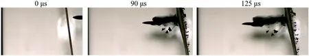
Fig.7.Shot 22V 369, Vi = 854 m/s, total yaw angle γt = 0.98°.
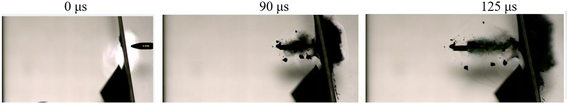
Fig.8.Shot 22V 370, Vi = 816 m/s, total yaw angle γt = 1.53°.
The summary of the performed tests is collected in Table 2,which gives an overview on the initial and residual bullet characteristics-the measured projectile’s initial yaw and pitch angles, as well as its velocity and the calculated projectile’s deviation angle and its residual velocity.The frames from the high-speed camera recordings are collected in the subsequent Figs.6-11.The frames presented the last moment before projectile stroke the target registered by the HS camera, which were described as the initial instant of the impact process-thus, they present the contractual time instant 0 μs.The subsequent frames were chosen 90 μs and 125 μs later.Fig.12 shows damages of the projectiles’cores at 245 μs.The angles of deviation after the plate perforation were calculated for the time instant 125 μs and they arepresented in Fig.13.It was assumed that the initial position of the projectile before hitting the plate(along the projectile axis of symmetry,the middle of the tip and the middle of the back part) sets the initial direction of the projectile passage.Whereas,the axis of the largest projectile core fragment determines the angle of its deviation in the observed plane(the pitch angle).Obviously,such angles are only a general estimation of the core deviation after plate perforation-it is difficult to estimate their accuracy.Fig.13 presents the measured angles recorded on the side view of the projectile’s core deviation after it perforated the target plate.
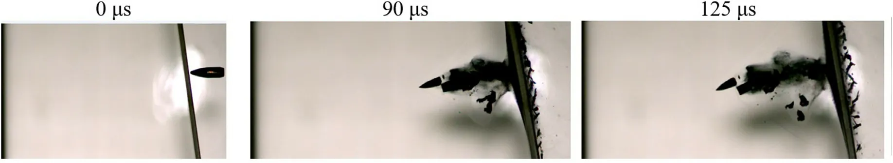
Fig.9.Shot 22V 371, Vi = 842 m/s, total yaw angle γt = 0.98°.

Fig.10.Shot 22V 372, Vi = 853 m/s, total yaw angle γt = 0.72°.
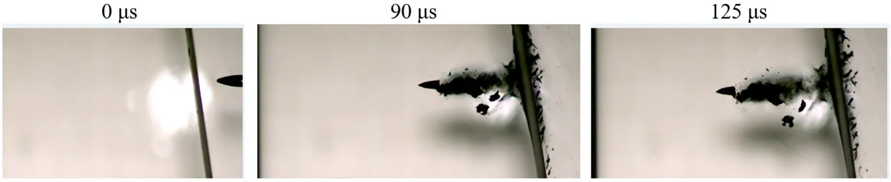
Fig.11.Shot 22V 373, Vi = 852 m/s, total yaw angle γt = 0.89°.

Fig.12.Magnifications of the damaged core (frames at 245 μs).
Fig.14 shows the front and back faces of the perforated steel plates.It maybe observed that the craters have either the circular(average diameter 5.9 mm) or slightly elongated shapes (with average dimensions 10.3 mm × 7.3 mm).Following the X-ray images,it may be observed that plates were not failing due to plugging[19].Hereby observed petalled peripheries of the exit holes characterized the ductile hole enlargement type of failure, typical for pointed bullets [20].
Summarizing the ballistic testing results, it may be concluded that:
1) The yaw and pitch angles of the performed shots would fulfill the requirements of the NATO Standard [9], i.e.the total yaw angle smaller than 5°(but this particular caliber is not used for evaluation of protection level according to the standardized procedure [9]).
2) Initial velocities varied between 815 m/s and 861 m/s (the original powder amount in the cartridge was not modified).
3) Total yaw angles varied between 0.48°and 1.53°.
4) Residual velocities-measured for the largest remained core pieces - varied between 660 m/s and 772 m/s.
5) The angles of deviation-measured for the largest core pieces-registered at 125 μs at the plane "X"-the side view, i.e.the view which the camera recorded.These angles varied between 4°and 5 14°.
6) The experiment proved that the projectiles’ cores may behave differently after perforating the oblique hard steel plates.It was observed that out of six shots:
- The core broke in the middle (two times)
- The core was fragmented into several irregular smaller pieces(two times)
- The core remained intact (once)

Fig.13.Measurements of the angles of deviation at 125 μs of the impact process.
- And once, it had a front part separated (sheared off) from the remaining two-thirds of its length.
It seems however that at the angle of inclination 10°, the projectile’s core is more prone to be broken or fragmented than to remain intact.In oblique impacts,due to the asymmetrical contact with the target, the transverse forces act on the projectile which may undergo an angular change in its direction of movement,while it passes through the plate.The asymmetric loading, to which the projectile is subjected,causes bending in the projectile.Therefore,a crack may initiate in a high hardness (thus, not very ductile) projectile’s core.
In the next section,there is presented an analysis performed in a FE code aiming to verify to which extend the numerical simulation is susceptible to the observed slight variations of the initial impact conditions.
3.Numerical modeling
The IMPETUS Afea Solver® is the non-linear transient dynamic explicit Finite Element code that takes advantage of a GPU technology.The parallelization of the solver is done with the GPU,meaning that large clusters of processors are not necessary to run a single large model.Using the IMPETUS® Lagrangian solver, the above described experimental configurations were represented numerically.Like in the experiment, the used projectile was 7.62 mm×51 FMJ/PB/HC AP P80 and as the target,the 4.5 mm thick Armox 500T steel plates were taken.
3.1.Meshing approach
For both tested components, the meshes were proposed automatically by the software.The projectile is meshed with 8,104 hexahedral elements(fully integrated,64 nodes and 64 integration points per element formulation)[25].A minimal distance between two nodes is 0.00009136 m.The characteristic element size is 0.000521 m.In the direct impact zone,the target plate was meshed by cuboid elements of the edge size 0.00053 m.Each element in the impact zone was additionally four times refined.In total,the default impact configuration consisted of 25,304 elements and 1,409,600 nodes.The parts of the configuration are connected employing a penalty-based surface-to-surface contact algorithm which uses a high order representation of the surface, as well as a default Coulomb friction coefficient equaled to 0.3.Fig.15 presents the projectile mesh and Fig.16 shows the zooms-into the impact zone of the steel plate.
3.2.Models for the materials of the impact configuration
The IMPETUS’ library contains a number of predefined target materials, as well as specific threats.The user may decide to keep the material model proposed by the software or to assign the model option and values of its parameters on its own.In the current approach, the choice of the material implemented into the threat and target was limited to the option proposed by the software in its library.Both the projectile of caliber 7.62 mm × 51 AP P80 (so, its jacket, cup and core) and the steel Armox 500T were available in the IMPETUS’ library (in the IMPETUS ver.7.0.1, the models for Armox 500T steel is not available anymore).This choice has at least two advantages-the modeled configuration remained free of the influences of the user with respect to the material models and a choice of its parameters and further,it is possible to verify to which extent the solutions proposed by the default software library may represent the tested impact configuration [21].
For the lead building the projectile cup and the brass of the jacket, flow stress vs.effective plastic strain is based on the calibration presented in Ref.[22].Elastic and thermal properties are in accordance to data presented in Ref.[23].The parameters fulfilling the models of the Armox 500T steel were applied following the 15 results of Ref.[24].
·Plasticity models
The material models proposed by the software were not changed in the carried out simulations.Thus.
(1) The plasticity model used to describe the flow behavior of the brass,lead and the Armox steel is the Johnson-Cook flow model *MAT_JC,Eq.(5).
(2) The plasticity model of the projectile core is the generic highstrength steel*MAT_HSS,Eqs.(6)-(8)the material model is specified for high-strength steels and hard metals in ballistic applications.The in-house approach used in IMPETUS defined simply an elastic material model with a brittle damage model, due to which the resulted yield stress is artificially high (and nonphysical).

Fig.14.(a) Front and (b) back faces of the perforated Armox 500T plates.
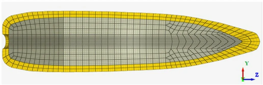
Fig.15.Mesh of the projectile 7.62×51 AP P80:cross-section through the jacket,core and lead cup [16].
The Johnson-Cook model formulation implemented in IMPETUS is as follow:
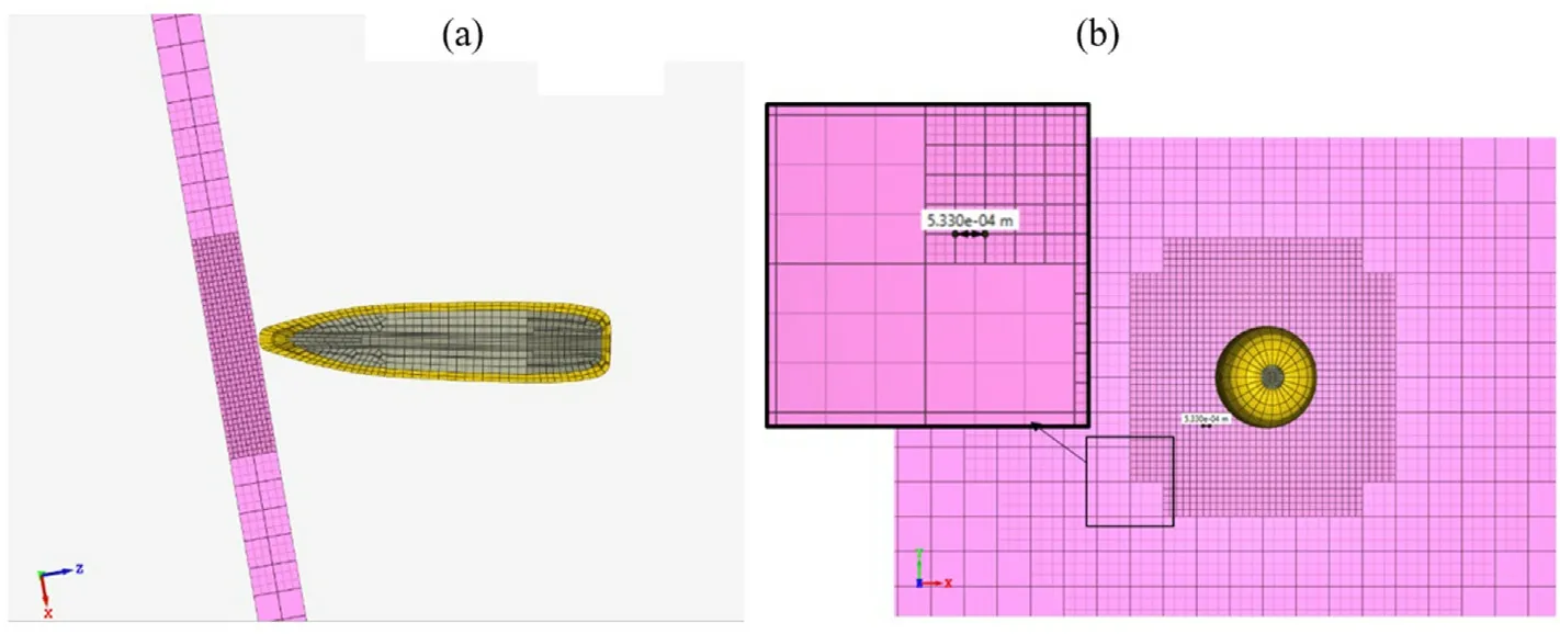
Fig.16.Impact zone of the target plate-meshing details: (a) Side view; (b) Front view.
Following the IMPETUS Manual[16],the yielding criterion is the function of the effective plasticstrain, its strain rate and temperature.The parameters for yield strength, A, and strain hardening, B and n, are determined from quasi-static tensile tests at room temperature.The parameters for strain rate hardening C andare identified based on the dynamic split Hopkinson pressure bar tests.The parametersTmandmare affecting the thermal softening of the described material.
The so-called model HSS-the generic model of a high-strength steel was developed and calibrated by IMPETUS specifically to describe the hard-core armor piercing projectiles.Following the description in the manual, in the *MAT_HSS, the yielding of a material occurs when the effective elastic stressreaches the yield stress σy.
In the yield stress expression,is a material softening function.Its purpose is to capture the effects of dynamic recrystallization or the formation of.adiabatic shear bands.is astrain measure that grows faster at high effective plastic strain rates andis the reference rate for strain rate hardening,are principal elastic stresses and mis the Hosford yield surface exponent.
Further,pis the material pressure,Kis the bulk modulus,αTis the thermal heat expansion coefficient andTrefis the reference temperature.
More detailed theoretical background, one may found in the IMPETUS User’s manual [16].
To model fracture of the materials composing the impact configuration, three different functions were used.
· Fracture models
(1)For brass and lead,a simple fracture criterion was applied-a crack initiates if the deviatoric erosion strain reaches its 300%:This is a default value proposed in the code, which was not modified.
An analysis of the lead filler and brass jacket’s deformation was not the study’s primary objective.Their presence affects the performance of the projectile [26,27], thus they must be accurately represented in the numerical simulation as well.The numerical simulations demonstrate that the jacket appears to behave in a realistic manner whereas the lead cup seems to be unrealistically ductile.Therefore, the values of these default failure conditions should be later-on updated.
(2) For the steel building the projectile core, the modified Hosford-Coulomb failure criterion is applied to approximate fracture occurrence.The material fails when the damage parameterDreaches 1:
where εfstrain at failure equals
The functiong(η,θ)is a function of the stress triaxiality η and the Lode angle parameter θ.The function parameters are denoted by symbolsa,b,candn.
(3) For the Armox 500T steel, the Cockcroft-Latham fracture model is valid.Ductile damage is there defined as
where σ1is the maximum principal stress,Wcis the damage parameter,is the effective plastic strain.
The complementing tensile damage is thus defined as
and
where σ1devis the maximum deviatoric principal stress andpis the material pressure.With βs=equals the maximum principal stress.The tensile fracture term only contributes to the damage growth if>σs.The material fails when the damage parameterDreaches 1.
Table 3 collects some general information about the materials and their modeling approaches.
The parameters of the applied models are summarized in Tables 4-6.Whereas,Table 7 presents the overview on the models’parameters.
3.3.Calculating position of the projectile after plate perforation
In IMPETUS,the global coordinate system is linked to the target,Fig.17.Contrary to the experiment in which the target is adapted to the demanded inclination angle,the angle of impact in the code is defined by a position of the projectile, Fig.17(b).The code enables defining the angle of target obliquity, as well as the pitch and yaw projectile’s angles.As it was stated in Section 2 and presented in Fig.4,IMPETUS respects the definition of the pitch and yaw angles presented in Ref.[9].
To avoid an ambiguity of the deviation angles calculation, the values of the angles were calculated based on the exact positions of the projectile’s core - i.e.theX,Y,Zcoordinates of the points determining the axis of symmetry of the projectile’s core beforeand afterplate’s perforation.The vectors were determined by the points indicating the core tip (XT,YT,ZT) and the middle of its"bottom part"(XB,YB,ZB),Fig.18.The vectordetermining the core position after the plate perforation was referred to its "idealized"initial position-when the yaw and pitch initial angles equal 0°.Such a superposition allowed a comparison with the experimental results,in which only the side view of the impacts is registered and an influence of the initial pitch angles is unknown.
and
The angle θ between the vectorof the projectile core axis in the position "0" and the vectordescribing the axis of the projectile core after the plate perforation(the position"f")is calculated using the 10 dot (scalar) product of these vectors, Eq.(15).
3.4.Verification of the calculation method
The calculation method of the after-perforation core deviation was verified based on the scenario of the normal impact configurations but with different yaw and pitch options:
(A) Normal impact, yaw and pitch angles are both equal 0°,Fig.19
(B) Normal impact, pitch angle equals 3°, yaw angle equals 0°,Fig.20
(C) Normal impact, pitch angle equals 0°, yaw angle equals 3°,Fig.21.
The cases (B) and (C) should result in the same total yaw angle after the plate perforation.After passing of the core through the plate,theXZangle in the case(B)should be of the same value of theYZangle in the case (C).
In the case(A),when the projectile hit perpendicularly the plate,with no pitch and yaw angles influence; the calculated total deviation of the projectile core was identified as 0.41°.In the planeXZ,the angle of deviation is 0.4°,in the planeYZ,the angle is calculated as 0.09°, Fig.19.The total deviation angle is not exactly zero even though the meshing of all the related components is symmetrical.This imprecision may occur due to the meshing method.Either, a failure and fracture propagation in the elements may result in a certain deviation.Additionally, as stated in the above subsection,values of the angles were calculated based on the positions of the projectile’s core coordinates of the points determining the core’s axis of symmetry before and after plate perforation.These calculations may contain slight inaccuracies, too.
In the case (B), the projectile’s pitch angle was assumed as 3°and the yaw angle 0°.The total yaw angle is then equaled to 3°.The assumed pitch angle is visible in the planeXZ, Fig.20(a).The total yaw angle after the plat perforation for that case is calculated as 9.17°,in the planeXZit is calculated as equaled to 9.1°, whereas in the planeYZ,the deviation angle was identified as 0.09°.In the case(C),the pitch angle is assumed as 0°whereas the yaw angle is taken as 3°.The assumed yaw angle is then represented in the planeYZ,Fig.21(b).After the plate perforation, the total yaw angle of the projectile core for that case is calculated as 9.2°,in the planeXZit is equaled to 0.1°, whereas in the planeXZ, the deviation angle was calculated as 9.1°.
Based on the above comparison, it maybe concluded that the method of angles calculations, as well as the results produced by the numerical simulation may be considered as reliable.The calculations give a similar deviation angles after the normal plate perforation when the projectile hits at the same total yaw angle but with the alternating pitch and yaw angles.
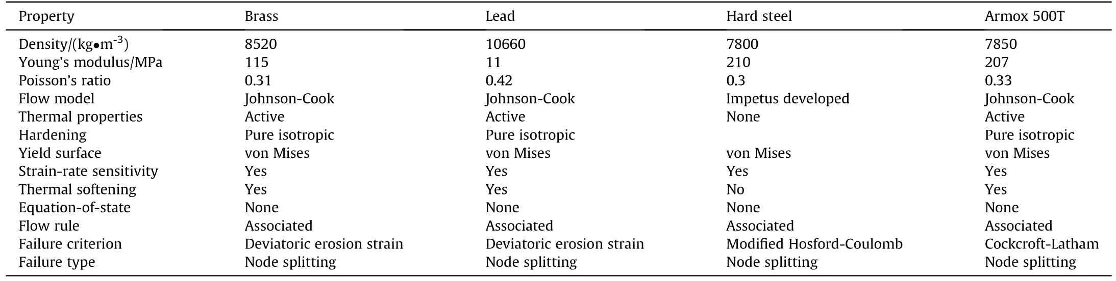
Table 3Overview on the modeling approaches.

Table 4Parameters of the JC model for the lead, brass and Armox 500T steel[16,22-24].

Table 5Parameters of the HSS model for the projectile’s core steel[16].

Table 6Parameters of the fracture models for the core steel and the Armox 500T steel,[16,24].

Table 7List of parameters used in the models.
4.Numerical results
The performed experimental shots have proven that the projectile’s behavior may differ significantly from one shot to another,Fig.12.Presumably then,the initial impact conditions play a role in the resulted projectile failure.
4.1.Modeling of the experimental cases
In the experiment, the target was inclined at 10°for the shot.The experiments showed that the subsequent six shots, during which the total initial yaw angles varied between 0.48°and 1.53°,resulted in different types of the residual core performance(intact,broken in the middle, fragmented).The numerical simulation was aimed to mirror the experimental set-up and repeat its initial conditions, i.e.the initial velocities of the projectile and the measured initial yaw and pitch angles.They were built on the default threat/target configuration and material modeling available in the card"terminal ballistic setting"of the IMPETUS software.The objective of the study was to verify if the numerical code may represent efficiently the experimental observations.
It must be noted that the calculations of the angle of deviation after the plate perforation have a certain error resulted from the post-processing of the experimental evidence based on which they were measured.Therefore,the comparison of the deviation angles obtained in the experiment and the simulation can be considered only as an approximation.Nevertheless,the experiment provides a clear visualization of the projectile core damages.
In Table 8, there is presented a comparison between the measurements taken due to the experiment and the calculations resulted from the simulations.In Fig.22, there are collected the visualizations of the side views of the performed shots and the suitable simulations.Similarly to the experiment, the time instant chosen to observe the projectile was set as 125 μs after the projectile hit the steel target.
It may be thus concluded that:
· The simulation of the experiments 22V 372, 370 and 369 modeled well the phenomenologically observed behavior of the cores.The core was intact in the shot 369 and broken in the shots 370 and 372.
· The simulations showed generally good tendencies of the core deviation after the plate perforation-at 120 μs,the pitch angles varied between 7°up to 10°comparing to the experiment, in which the core deviation angle was estimated between 4°and 14°.
· The calculated residual velocities were close to the experimental results (the average value of 740 m/s calculated for the experiment and the average value of 754 m/s calculated for the simulations).

Fig.17.(a)Default software position of the impact configuration at 10° inclination;(b)Global coordination system rotated, so that the numerical view might be compared with the experimental one.
· In each modeled case,the initial projectile spinning of the value 21050 rad/s was assumed.In average,the value of the spin after the plate perforation was calculated as 18540 rad/s.This characteristic is experimentally not verified.
However,
· In the three(out of five)cases,the default configuration did not result in the core breakage.
The computations produced a nearly perfect approximation of the residual velocity of the projectiles’cores;the average error was less than 3%(see Table 8).When the residual velocity is of interest in engineering approaches,a high efficiency of the IMPETUS should be valued.However, the deviation angles of the projectiles’ debris were less precise when compared to the values of after-perforation pitch angle of the cores determined experimentally based on the HS camera movies taken from the side.The average discrepancy between measured and calculated pitch angles is 34%,with a range of the simulation accuracies varied between 4 and 63%.It should be noted that the method used to measure pitch angles after the experimental testing may need improvements and is hampered by a hard-to-estimate inaccuracy.

Fig.18.(a)Superposition of the idealized position(no pitch and yaw deviation)initial position and the after-perforation position of the projectile’s core;(b)Core axis of symmetry.

Fig.19.Perpendicular impact with the pitch and yaw angle equals 0°.View of the plane XZ: (a) Projectile before hitting the plate; (b) Projectile after the perforation.
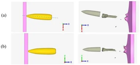
Fig.20.Impact with the pitch angle equaled 3° and the yaw angle equaled 0°.Side view on the plane (a) XZ and (b)YZ.
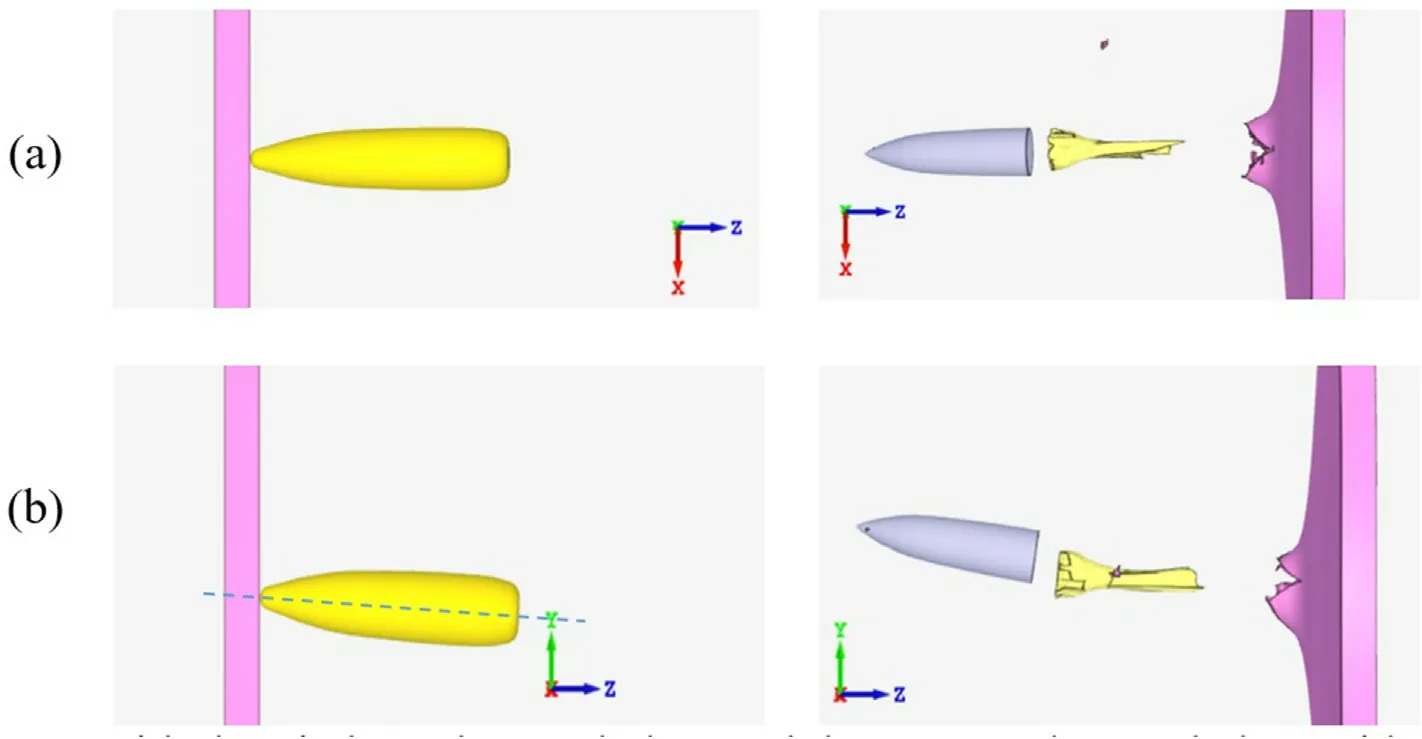
Fig.21.Impact with the pitch angle equaled 0° and the yaw angle equaled 3°.Side view on the plane (a)XZ and (b) YZ.

Table 8Comparison between the experimental and numerical results and the difference between the experimental and numerical results.
Users of IMPETUS may access the material card and modify values of the constituent functions applied in calculations and thus,affect the simulation according to alternations introduced by them.A reduced parametric study for the experimental case 22V 369 is therefore performed.This is the experimental test, in which the pitch and yaw angles upon an impact did not cause the projectile’s core fragmentation.Table 9 displays the results of the study.The analysis shows that reducing of Hosford-Coulomb damage parametersa,b,n,cdoes not affect the core sensitivity to a crack initiation.Decreasing values of the spall fracture stress sensitivity does not change the core behavior either, however their increase resulted in a more significant cracking of the projectile’s core.A similar effect is observed when the threshold of spall stress was reduced.With the decreasing values of σs,a number of cracks in the core and their range increased.Knowing that high-strength metals are susceptible to tensile stresses,this effect may be considered as justified.
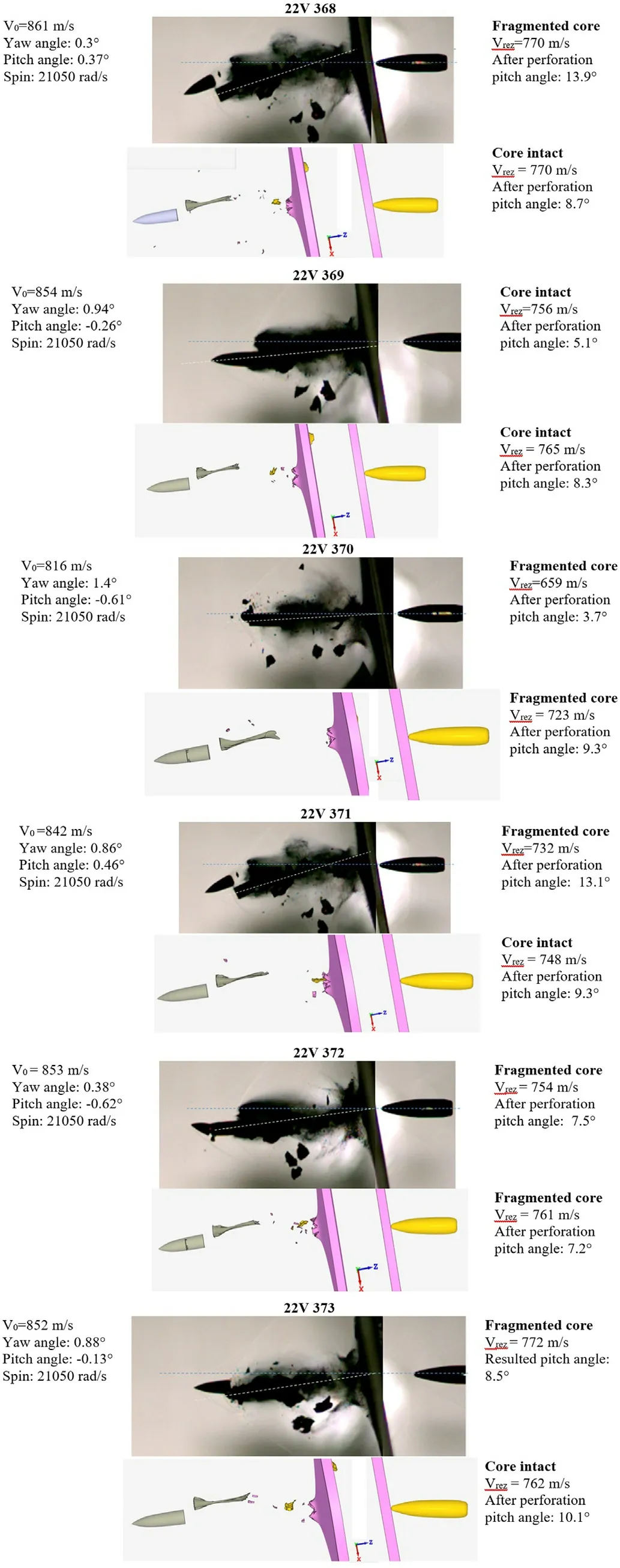
Fig.22.Comparison between the experiments and the simulations.
The study also demonstrates that varying the fracture model parameters does not affect the core fracturing as easily as it might have been anticipated.Experimentally, it was observed that the core remained intact in a single test, whereas the cores cracked more readily in most combinations of the yaw angles.As in the simulation varying the HC parameters does not affect greatly the core sensibility to onset of cracks,this may prove that the position of the projectile upon an impact plays a role in the resulting core performance.
Nevertheless, user-introduced modifications of the constitutive function should be always undertaken with caution and based either on the material characterization or on a detailed parametric study of the analyzed experiment test.In the discussed case,modifications implemented in the software material modeling should result in an acceptable description of all aforementioned experimental scenarios of the core behavior.
4.2.Discussion on the numerical results
Figs.23 and 24 present the visualizations of the damage parameter for the projectile’s core for the experiments 22V 369 and 22V 372.These are two different experimental cases, which were well repeated by the simulations.After the plate perforation, the projectile’s core remained intact in the case 369 and the core was broken in the case 372.The differences between the measured initial pitch and yaw angles were not large-for the shot 369:the pitch angle was measured as 0.26°and theyaw angle as 0.94°and for the shot 372:the pitch angle equaled to 0.62°and theyawangle to 0.38°.The collected images present five time instants proceeding an occurrence of the crack in the core of the experiment 372-i.e.the time period between 27.6 μs and 31.2 μs.One may observe the target and the core on the side view(planeXZFigs.23(a)and 24(a))and the"bottom"of the core(planeYZFigs.23(b)and 24(b)),where the crack started and propagated leading to the full core fracturing in the case 372.
Fig.25(a) presents the development of the damage parameter for an element which failed as the first in the simulation 372(indicated with an arrow).It is seen that about the 30 μs in the case 372, the damage parameter reached value 1.0 and following the fracture definition, it proceeded a crack initiation.The technique which was chosen to enable fracture in the projectile’s core was the node splitting,so the failed elements were not eroded and deleted from the mesh-they remained in the simulations but the connectivity with their neighbors was broken.In the modeled scenario 369,the damage parameter reached the value 0.7,the stress-strain state in the core did not cause a sufficient straining of the material,so that the failure criterion was activated.One may observe in Figs.25(b)and 25(c)that the values of the effective stress and strain in the directionZdo not vary much for the tests 369 and 372.About the time instant 30.0 μs, the core of the projectile in the impact scenario 372 was characterized by the effective stress of higher values(3100 MPa for the case 372,and 2000 MPa for the case 369),and similarly the strain ZZ(for the experiment 372,strain reached 0.014, whereas the experiment 369 it was calculated as 0.01).In Figs.25(d)and 25(e),it may be also observed that the values of the Lode angle parameter and the triaxiality factor have a generally similar course.
The triaxiality stress factor and the Lode angle parameter are the arguments of the Hosford-Coulomb failure criterion which modeled the projectile’s core failure.Failure criteria which account for these two arguments become more and more popular in dynamic modeling.Therefore, it is interesting to observe how these measures develop through the penetration phase up to themoment of the crack occurrence in the case 22V 372 (and to the equivalent moment in the not-fractured scenario of the case 22V 369).The detailed discussion on the not-intuitive parameter of the Lode angle may be found in the study [28].The Lode angle parameter together with a more straightforward meaningful parameter of the stresses triaxiality may be considered as the useful numerical measures and a convenient way of presenting stress states underwent by an analyzed component.Exemplary discussions may be found in works [29,30].

Table 9Parametric study of the sensitivity of the projectile’s core model.
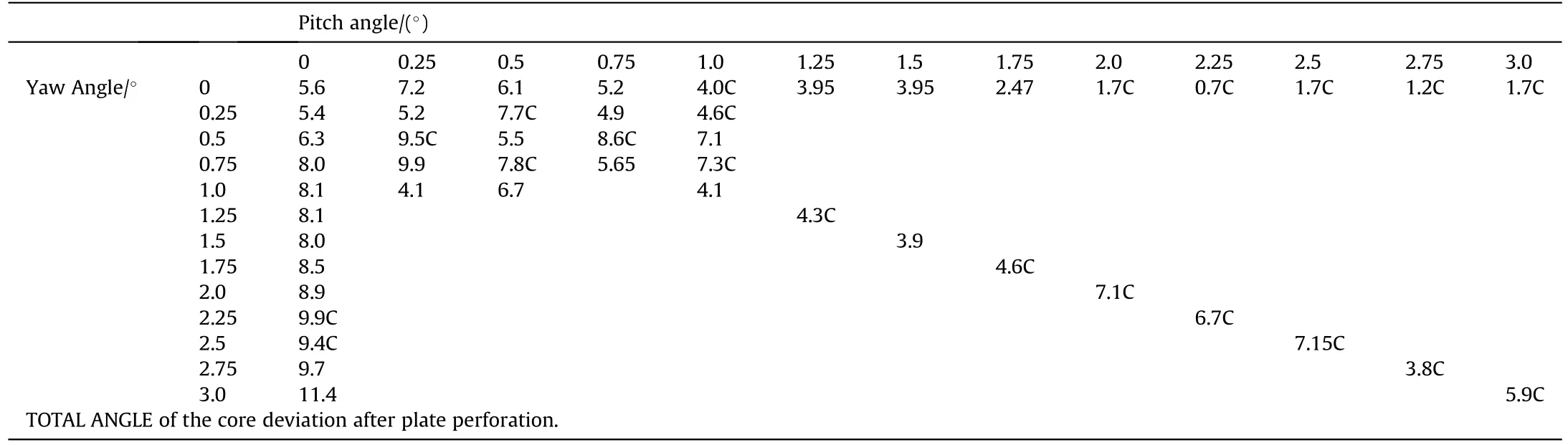
Table 10Matrix of the total angles of deviation calculated for the projectile core in dependence of the initial impact angles("C"-projectile’s core is fractured).Target inclination 10°NATO.
Fig.26 shows the maps of the stress triaxiality for the target steel plate at the beginning of the penetration process and for the projectile core just before the crack initiation.It may be observed that the rear part of the plate is bent (denoted by values of the triaxiality factor about 0.67 and the red color)and the front part of the plate just before the projectile’ stip is compressed (values reaching-0.67 and the blue color).Due to the contact with the plate,the projectile’s bottom part was bent (red color, triaxiality exceeding 0.67) and the upper periphery compressed (blue color,triaxiality factor about -0.67).The shearing state of stresses is denoted by the values of the triaxiality factor about 0 (and the green color).
The presentation of the dependences between the effective strain and the triaxiality factor and the normalized Lode angle parameter in Figs.25(d) and 25(e) allows to conclude that for the case 22V 372 up to 21.6 μs, the analyzed elements underwent a strong compression (the triaxiality exceeded -2/3, the Lode angle parameter about - 1).Later-on, between 21.6 μs and 24 μs in the both cases 372 and 369,the elements were sheared but not strongly enough to cause their failure.Finally, the loading path of the element in the case 372 led to the plain strain tension stress state(at 28.8 μs, the triaxiality factor reached the value about 0.35, the Lode angle was about 1), which was the stress state in which the element failed.A similar loading profile occurred to the equivalent element in the case 369,but an extent of the shear and tension state was not high enough that a fracture initiated.
The projectile’s core, as it may be seen on Fig.26(b), was in a direct contact with the plate along its periphery.The stress triaxiality map reveals that its upper part was compressed,whereas the bottom part was slightly stretched.The crack initiated because high-strength steels are susceptible to straining at tensile loading regimes.The numerical outcomes of the experiment 22V 372 are presented in further detail in Fig.27, on which the evaluation of stresses and strains can be followed for three nodes close to- and inside the crack (node B).Because node-splitting technique was employed to simulate fracturing, the over-strained elements were not removed but their nodes were broken apart.As it can be seen,the node’s B damage parameter reached 1 at time instant 30 μs,yet it was included in the calculation and still slightly loaded.An occurrence of the crack caused the release of straining of the nodes A and C.Their damage parameters hit 0.9 but after the crack appeared,the values of damage felt down quickly to the initial state close to zero.For all 3 nodes,the evolution of effective stress,stressZZ, and strainsZZwas comparable.Just before the onset of crack,these values reached their maximum for all three nodes and further, they decreased.
Based on the above discussion, it is important to note how refined are the interactions between the stress states preceding an onset of the crack in the oblique impact configuration with the influence of the initial pitch and yaw angles.It may be observed that the slight change of the angle of attack may result in slightly different loading states of the projectile’s core.As the simulation shows,a small bit more of shear-tensile loading decides if the crack occurs or not.
Fig.28 presents the front and back view on the crater which remained in the steel plate after the projectile passage.For all simulated cases,it has a regular circular shape and the diameter of 6.5 mm.Fig.14, which gives an overview on the steel plates perforated experimentally,shows that the entry and exit holes may have a regular circular shape but they maybe also elongated.The diameter in the circular craters is of the value very similar to the approximation obtained numerically,whereas the elongated entry holes were not repeated by the simulations.The features of the crater observed in the experiment, i.e.smooth entry and a slight petalling on the rear target side are correctly modeled in the FE simulations.
Despite not fully precisely simulated after-perforation behavior of the projectile’s core in comparison to the performed experiment,a parametric study was realized using the default IMPETUS configuration.Its results are summarized in the next section.
4.3.Matrix of the deviation angles
The matrix of the total angle deviation independence on the initial yaw and pitch angles was calculated for the configuration in which the steel plates were inclined at 10°NATO.The targets were made of ARMOX 500T and the threat was the 7.62 mm×51 AP P80 projectile.The projectile spin was set as 21050 rad/s.The plate size(117 mm×117 mm),projectile velocity(833 m/s),material models(see Section 3),time of calculations(90 μs)are default setting in the IMPETUS terminal ballistics modeling scenario.The total angles of the core deviation were calculated referring to the position of the core,when there was no pitch and yaw angle influence.
Table 10 presents a matrix of dependences between the initial pitch/yaw angles and the final core deviation given by the total deviation angle.This matrix shall be considered as a purely numerical approximation of the core deviation tendencies.As the limitations and drawbacks of the code modeling approaches are presented in the previous sections,the matrix may be claimed to be as good as the modeling techniques allow.Nevertheless, based on the performed simulations, some tendencies of the projectile core performance due to perforation of the HS steel plate aligned at 10°may be noted.
With the increasing values of the initial pitch and yaw angles of the projectile, the deviation angle of the projectile core after the plate perforation increases.
· Yaw angle has a more significant influence on the total core deviation than the pitch angle.
· Core fragmentation occurs more likely when the inclination is affected by both pitch and yaw angles.
The presented matrix obtained numerically indicates a tendency of the projectile core performance in dependence to the initial yaw and pitch angles characterizing the impact moment; an experimental confirmation of this finding would be a challenging but interesting perspective.
5.Conclusions
The numerical study was based on the experimental investigation of the behavior of the small-caliber 7.62 mm × 51 AP P80 projectiles shot against the 4.5 mm thick ARMOX 500T steel plates,inclined to the shots at the angle of 10°NATO.
The terminal ballistic testing comprised six shots, which each time had the different initial yaw and pitch angles at the impact moment-the total yaw angles varied between 0.48°and 1.53°.The resulting damages of the projectile core after the plate perforation varied depending on the case.Out of six shots,two shots resulted in a breakage of the core in the middle,three times the projectile core was fragmented in severalpieces and once the core remained intact.

Fig.25.Variables history for the element indicated by an arrow for the cases 22V 369 and 22V 372: (a) Damage; (b) Effective stress; (c) Strain ZZ; (d) Effective strain vs stress triaxiality (time instances for the case 372); (e) Effective strain vs normalized Lode angle (time instances for the case 372).

Fig.26.Stress triaxiality in: (a) Middle-cross-section of the steel target plate at 10 μs and (b) of the periphery of the projectile at 28.8 μs.
Despite being based on a small number of shots, this study demonstrates the intricacy of interactions that can occur in a setup used in terminal ballistics investigations.NATO STANARD AEP-55[9] requires a verification of the total yaw angle upon an impact but the performed testing proved that even total yaw angles much lower than required 5°may cause different types of the projectile core failure.The Standard suggests that yaw angles were measured by any suitable method-i.e.yaw card, orthogonal photographic or flash X-ray system, Doppler radar system,etc., which may provide results with different accuracy.
Knowing that an impact angle affects the performance of the projectile after target perforation, it would be of interest to regularize the standardized yaw angle measurements.

Fig.27.Case 22V 372:(a)Maps of the effective stress(bottom view).Graphs for 3 nodes in the fracture zone of:(b)Damage parameter;(c)Effective stress;(d)Stress ZZ;(e)Strain ZZ.
Since a single experimental example may not be representative and may lead to misinterpretation of experimental results, the information on yaw angles at the moment of impact should also be taken into consideration in academic studies.
Last but not least, a tendency to fracture observed for highstrength, high-hardness projectiles’ cores under even slight bending loads occurred during asymmetrical or oblique impacts,may also be considered as an effective defeat mechanism, which might be further optimized (e.g.Refs.[31-33]).
The experimental ballistic testing proved how complex the impact tests are.The initial impact conditions of the performed shots did not vary much but they resulted in different types of the residual core damages.An accurate representation of such an experiment with a slight variation of initial conditions and the different resulting projectile failure types is a challenge for numerical modeling,independently of a chosen calculation software.
The numerical simulations were performed using the default setting for the terminal ballistic scenarios available in IMPETUS Afea solver®.All objects required to represent the experimental configuration were available in the software library.The computation cost of each simulation was low, thus dozens of simulations were performed in a reduced time and without much effort necessary for their preparations.A simplicity of setting-up the test configuration should be hereby highlighted.
The numerical results showed generally a correct tendency in calculations of the core deviation.The calculated after-perforation pitch angles varied between 7.3°up to 10.5°, whereas in the experiment the average core deviation in the observed plane was estimated as close to 9°.The calculated residual velocities were close to the experimental results (the average value of 740 m/s calculated for the experiment and the average value of 755 m/s calculated for the simulations).The simulation captured the stressstrain fields in the projectile’s core which complex game causes a presence of crack or its lack.It should be emphasized that small changes of the initial projectile position in oblique impacts result in much different performances of the projectiles’ cores.Both the simulations and the experimental investigation prove that observation.
Acknowledgements
Sincere thanks are expressed to Mr.Paul Beillard (ISL), Mr.Laurent Sinniger(ISL)for performing the ballistic investigation and to Mr.Fabien Rondot(ISL)for valuable discussions.A feedback of Dr.Jerome Limido(IMPETUS)and Mr.Jiri Dohnal(PROTYPA)is hereby also acknowledged.

- Defence Technology的其它文章
- Reply to the note by Li Piani et al.
- Book review:“Impact Engineering:Fundamentals,Experiments and Nonlinear Finite Elements”By Marcilio Alves(2020)Price at Amazon: US$ 85.67.www.impactbook.org
- Note on: “Ballistic model for the prediction of penetration depth and residual velocity in adobe: A new interpretation of the ballistic resistance of earthen masonry”
- Remote sensing of air pollution incorporating integrated-path differential-absorption and coherent-Doppler lidar
- Micro defects formation and dynamic response analysis of steel plate of quasi-cracking area subjected to explosive load
- Experimental and numerical study on protective effect of RC blast wall against air shock wave