
Twisted Integration of Complex Oxide Magnetoelectric Heterostructures via Water-Etching and Transfer Process
2024-02-09 08:05:02GuannanYangGuohuaDongButongZhangXuXuYananZhaoZhongqiangHuMingLiu
Nano-Micro Letters 2024年1期
Guannan Yang, Guohua Dong✉, Butong Zhang, Xu Xu, Yanan Zhao,Zhongqiang Hu✉, Ming Liu
ABSTRACT Manipulating strain mode and degree that can be applied to epitaxial complex oxide thin films have been a cornerstone of strain engineering.In recent years,lift-offand transfer technology of the epitaxial oxide thin films have been developed that enabled the integration of heterostructures without the limitation of material types and crystal orientations.Moreover, twisted integration would provide a more interesting strategy in artificial magnetoelectric heterostructures.A specific twist angle between the ferroelectric and ferromagnetic oxide layers corresponds to the distinct strain regulation modes in the magnetoelectric coupling process, which could provide some insight in to the physical phenomena.In this work, the La0.67Sr0.33MnO3 (001)/0.7Pb(Mg1/3Nb2/3)O3-0.3PbTiO3 (011) (LSMO/PMN-PT) heterostructures with 45° and 0° twist angles were assembled via water-etching and transfer process.The transferred LSMO films exhibit a fourfold magnetic anisotropy with easy axis along LSMO < 110 >.A coexistence of uniaxial and fourfold magnetic anisotropy with LSMO [110] easy axis is observed for the 45° Sample by applying a 7.2 kV cm-1 electrical field, significantly different from a uniaxial anisotropy with LSMO [100] easy axis for the 0° Sample.The fitting of the ferromagnetic resonance field reveals that the strain coupling generated by the 45° twist angle causes different lattice distortion of LSMO, thereby enhancing both the fourfold and uniaxial anisotropy.This work confirms the twisting degrees of freedom for magnetoelectric coupling and opens opportunities for fabricating artificial magnetoelectric heterostructures.
KEYWORDS Magnetoelectric heterostructures; Twist angle; Epitaxial lift-off; Magnetic anisotropy; Ferromagnetic resonance
1 Introduction
The ability to control strain in magnetoelectric heterostructures has been one of the key approaches to manipulate a vast range of functional properties, since the strong electronic interactions in complex oxide materials, especially the 3d orbital electrons, make its physical phenomena sensitive to lattice deformations [1, 2].Generally, as for strain engineering, the lattice mismatch between epitaxial film and substrate modulates the phase transitions [3], enhances ferroic order [4, 5], and modifies charge conduction [6, 7].
However, the epitaxial growth has fundamental limitations and prevents the unrestricted manipulation of strain in film.Firstly, the maximum strain is determined by lattice mismatch during the epitaxial growth [8, 9].Secondly,because epitaxy only occurs for a relatively limited set of materials, whether the type and orientations of the materials or the strain coupling modes driven by magnetic or electric fields are restricted [10-12].Thirdly, the clamping effect constrains the strain transfer process [13].These reasons impose a serious obstacle to enhancing magnetoelectric coupling.
In recent years, epitaxial lift-offand transfer methods have been developed, enabling the integration of heterostructures without the restriction of crystal orientation and type.These techniques, such as chemical etching La0.7Sr0.3MnO3[14], SrRuO3[15], MgO [16] and SrCoO2.5[17], mechanical lift-off by graphene [18], as well as water-soluble Sr3Al2O6[19, 20], have produced a broad range of new heterostructures, such as CoFe2O4(CFO)/0.7Pb(Mg1/3Nb2/3)O3-0.3PbTiO3(PMN-PT), CFO/Y3Fe5O12(YIG) [18],La0.67Sr0.33MnO3(LSMO)/PMN-PT [21] and SrTiO3(STO)/Ce0.8Gd0.2O1.9(CGO) [22].Meanwhile, by applying pressure on the thin films in direct contact with substrates, the epitaxial film can achieve one-step transfer, thus resulting in higher quality [23].Based on these, referring to Moire heterostructures of 2D materials [24, 25], it could be anticipated that the twist angle between ferroelectric and ferromagnetic oxide film can also extend the degrees of freedom in strain control of magnetoelectric heterostructures [26].However,there are few related research so far.
In this work, an artificial assembly method is used to combine a (001)-oriented ferromagnetic LSMO film and a (011)-oriented ferroelectric single-crystal PMN-PT substrate, which is impossible realized through directly epitaxial growth.LSMO film is epitaxially grown on (001)-oriented SrTiO3(STO)-buffered Sr3Al2O6(SAO) layer by pulse laser deposition (PLD).After removing SAO layer, LSMO film is transferred to the PMN-PT with the twist angle between ferroelectric substrates and ferromagnetic films, such as 0° (0° Sample) and 45° (45° Sample).Before and after transfer, the easy axis within the thin film surface points to LSMO < 110 >, while the in-plane squareness of the magnetization curve (Mr/Ms) significantly increases after the lift-offprocess.By applying a 7.2 kV cm-1electric field,a coexistence of uniaxial and fourfold magnetic anisotropy with LSMO [110] easy axis is observed for 45° Sample,which is significantly different from the uniaxial anisotropy with LSMO [100] easy axis for 0° Sample.Moreover, the inplane angle-dependent ferromagnetic resonance field (FMR)results exhibit similar magnetic anisotropy, indicating that the 45° rotation of LSMO film on PMN-PT gives rise to different strain modes and lattice distortions from 0° Sample.This study demonstrates the twist angle degree of freedom for performance regulation in magnetoelectric heterostructures and opens up opportunities for fabricating artificial magnetoelectric heterostructures.
2 Experimental Section
2.1 Growth and Transfer of LSMO Thin Films
PLD was used to epitaxial growth sacrificial layer SAO and ferromagnetic film LSMO in turn on a single-sided polished STO (100) single crystal.The substrates’ temperature was 800 °C.The pulsed laser energy was 180 mJ and the frequency was 2 Hz.Meanwhile, the O2partial pressure was 20 and 30 Pa for the deposition of SAO and LSMO, respectively.Magnetron sputtering technology was used to grow electrodes of 50 nm metal Pt on the upper and lower surfaces of (011)-oriented PMN-PT single-crystal substrates.A resin glue (G1, Gatan, hardener/resin = 1:10) was used to stick as-grown LSMO films onto the platinized PMN-PT substrates at the twist angle of 45° ± 2° (45° Sample) and 0° ± 2° (0° Sample), respectively.During the transfer process, a continuous pressure was applied to the LSMO/PMNPT heterostructures, and it was heated at 120 °C for 30 min to ensure complete curing.Finally, the sacrificial layer SAO was dissolved in deionized water for 12 h.
2.2 Materials Characterizations
A high-resolution X-ray diffractogram (XRD) with θ - 2θ scanning (PANalytical X’ Pert Pro MRD) was used to characterize the crystallinity of LSMO/SAO/STO(001) and LSMO(001)/PMN-PT(011).And an atomic force microscope (AFM) (Bruker Dimension Inc.) was used to characterize surface morphology of the LSMO/SAO/STO (001)heterostructure.Meanwhile, the microstructure and epitaxial nature of the film and interface was characterized by scanning transmission electron microscopy (STEM) (JEOL JEMARM 200F) with a probe spherical aberration corrector.
2.3 Magnetic Measurement
The M-H hysteresis loops were measured by a vibrating sample magnetometer (Lake Shore 7404).An X-band(9.3 GHz) electron paramagnetic resonance system (JESFA200) was used for FMR measurements.The sample was placed in a rectangular cavity working at the TE102mode with a 360° rotating base.Electric field tuning FMR was explored by in situ poling the PMN-PT (011) along the outof-plane direction with Pt as electrode.
3 Results and Discussion
3.1 Fabrication and Structure of Artificial Magnetoelectric Heterostructures
To obtain high-quality LSMO films, SAO (35 nm) and LSMO (70 nm) are sequentially grown on STO (001) substrates using PLD.Then, LSMO/SAO/STO(001) is stuck onto the (011)-oriented platinized PMN-PT.The PMNPT(011)/LSMO/SAO/STO(001) is immersed in dissolved water to etch the sacrificial SAO layer.Two types of LSMO/PMN-PT are fabricated as shown in Fig.1a (x||LSMO[100],y||LSMO[010], a||PMN-PT[01-1] and b||PMN-PT[100]).The crystallinity of LSMO/SAO/STO heterostructure asgrown and LSMO/PMN-PT transferred from STO substrate is detected by XRD as shown in Fig.1b.Only (00l)-oriented diffraction peaks are found by θ-2θ scans, confirming the high crystallinity of LSMO/SAO/STO heterostructures and transferred LSMO films.All the (00l)-oriented diffraction peaks of LSMO films shift to the left, suggesting the increase of the lattice constant c with the disappearance of epitaxial stress after the transfer process.Figure 1c shows the lowmagnification cross-sectional Z-contrast STEM images of an as-grown LSMO/SAO/STO heterostructure.High-resolution STEM image of the LSMO/SAO interface reveals that a sharp interface exists between LSMO and SAO.Uniformly distributed atoms and the consistent structure indicate that the LSMO/SAO heterostructure is coherently strained and fully epitaxial.Meanwhile, the low root mean square surface roughness of LSMO/SAO/STO heterostructure is confirmed by the AFM (Fig.S1).Figure 1d shows the cross-sectional STEM image of the transferred 45° Sample, and LSMO film is tightly stuck and has a flat interface.The high-resolution image along PMN-PT [100] exhibits the LSMO [110] lattices.Meanwhile, LSMO [110] and PMN-PT [100] diffraction pattern is observed by cross-sectional selected area electron diffraction (SAED), as shown in Fig.1e, confirming the twist of crystal orientation in the heterostructure.
3.2 Magnetic Evolution of As-Grown and Transferred LSMO Films
The in-plane magnetization curves of the LSMO films before and after the transfer process exhibit the same magnetization features with coercive field only decreasing from 39 to 25 Oe, as shown in Fig.2a.However, for the out-of-plane, coercive field increases from 130 to 275 Oe (Fig.S2).Moreover, the obvious resonance field(Hr) shift indicates the strain relaxation after the transfer,as shown in Fig.2b.Due to the compressive stress from the STO substrate, the easy axis of the epitaxial LSMO film points to the < 110 > direction.However, the release of epitaxial strain causes 0.46% out-of-plane lattice constant increases, which could lead to a significant reduction in out-of-plane demagnetization energy (Note S1).Therefore, theHrdecreased by 1028 Oe.Besides, the biaxial in-plane anisotropy and an enhancedMr/Msafter transfer are observed, as shown in Fig.2c.The FMR results further exhibit a slight biaxial in-plane anisotropy and a 150 Oe increase ofHrafter strain release, as shown in Fig.2d.
3.3 Magnetoelectric Coupling of LSMO/PMN-PT
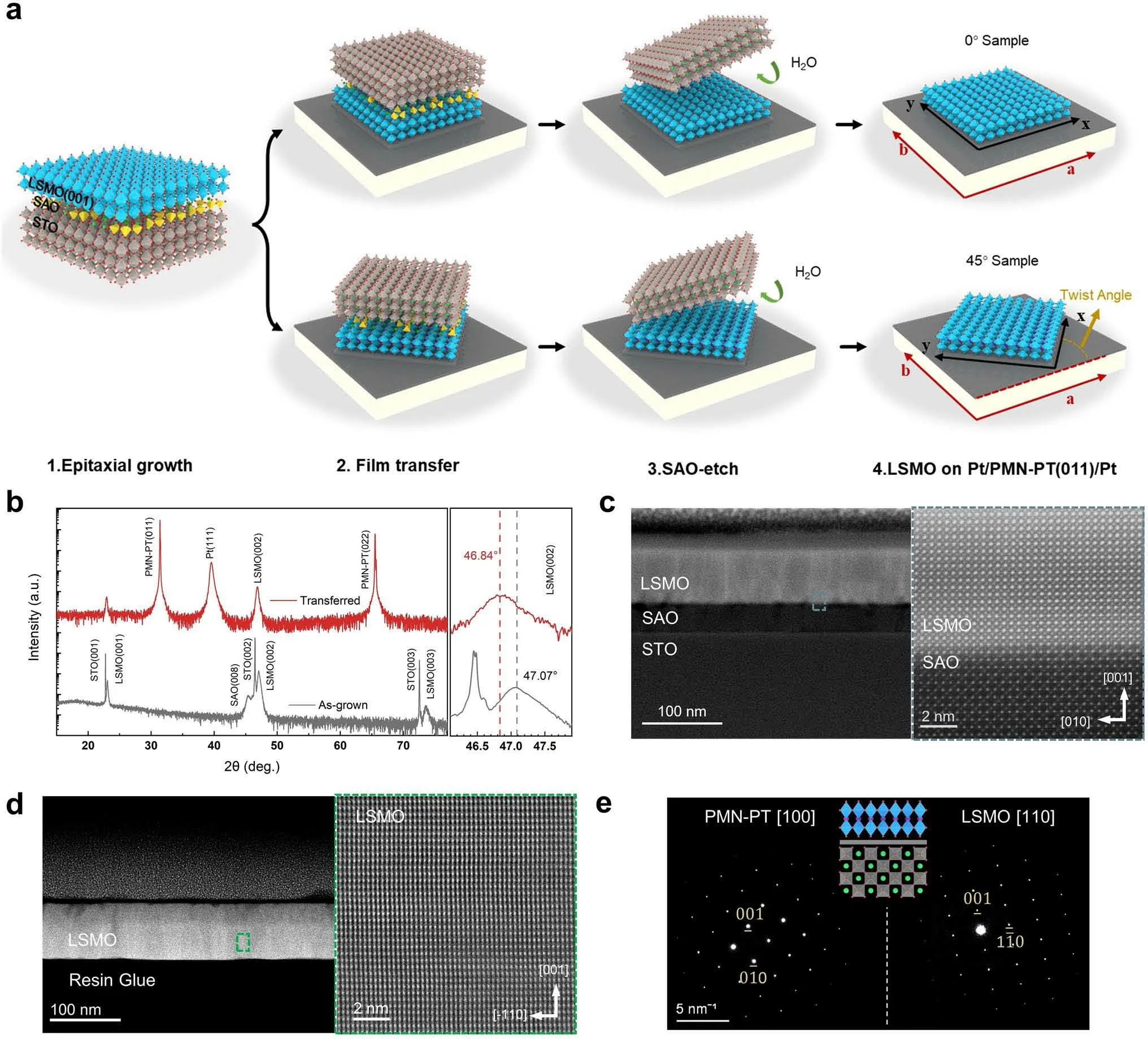
Fig.1 a Schematic diagram of LSMO film lift-offand transfer processes and structure of 0° Sample (top) and 45° Sample (down).b XRD patterns of the as-grown LSMO/SAO/STO (gray) and transferred LSMO on Pt/PMN-PT (red).c Low-magnification cross-sectional STEM image of an as-grown LSMO/SAO/STO heterostructure and high-resolution STEM image of the LSMO/SAO interface.d Cross-sectional TEM and highresolution STEM images of artificial LSMO/PMN-PT heterostructures with 45° twist angle.e Cross-sectional selected area electron diffraction images of artificial LSMO/PMN-PT heterostructures with 45° twist angle and the schematic diagram of the cross-sectional lattice structure for 45° Sample
To confirm the magnetoelectric coupling of LSMO/PMNPT, an electric fieldEis applied along the PMN-PT [011], as shown in Fig.3a.TheHr-Ecurve exhibits a loop-like behavior, as shown in Fig.3b, which originates from the non-180° (71°and 109°) polarization switching [28] and electricinduced irreversible R-O phase transition [29].The similar results have been reported by Liang, etc.[30, 31].R-O phase transition induces compressive strain along the in-plane PMN-PT [100] and tensile strain along the PMN-PT [0-11];meanwhile, polarization switching gives rise to a similar strain mode with R-O phase transition [32, 33].Ultimately,the presence of these two mechanisms results in the looplike curve.For both two heterostructures, theHrswitches at ± 1.6 kV cm-1and saturates at 7.2 kV cm-1, which provides two nonvolatile states of high and lowHrat 0 kV cm-1.
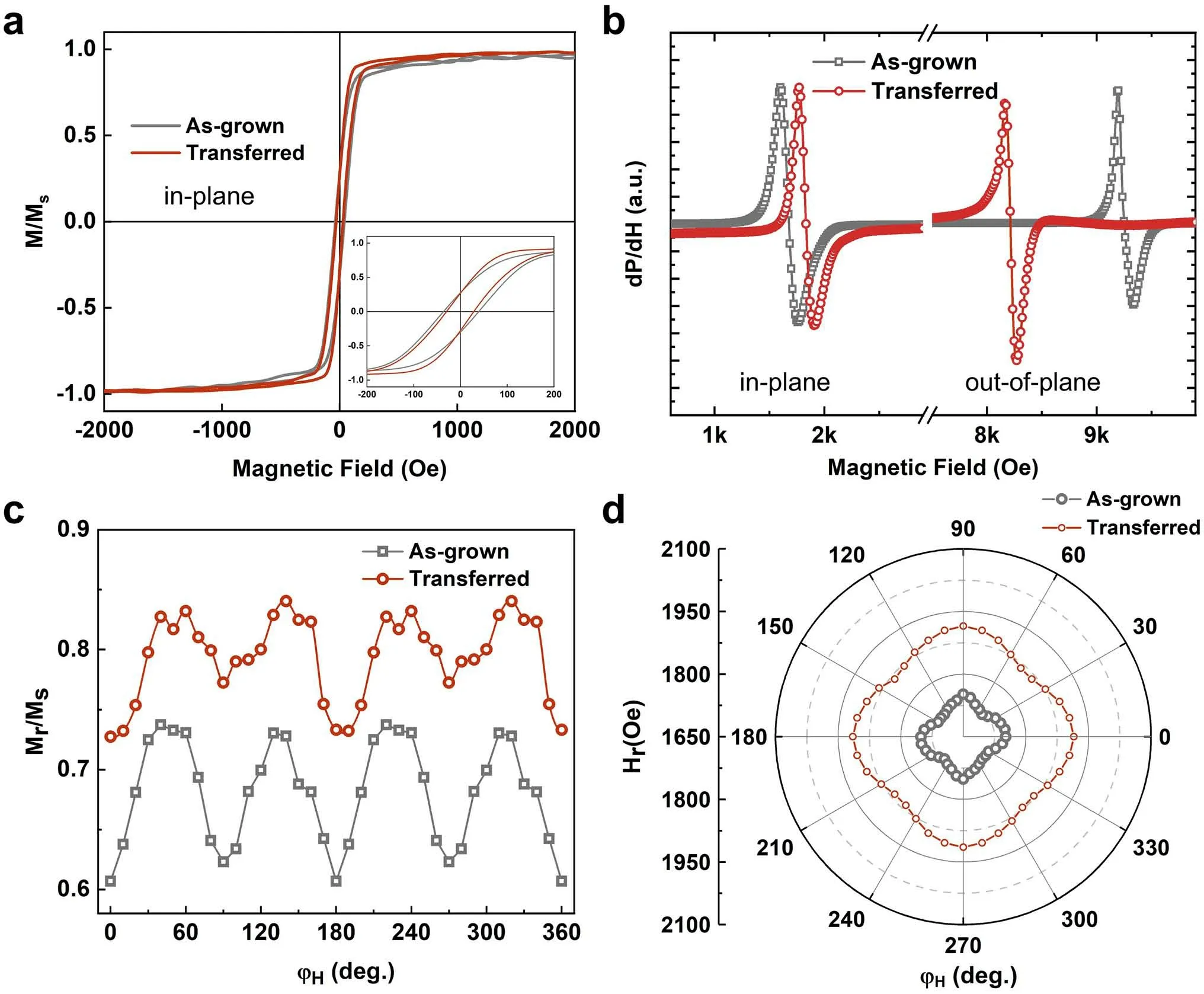
Fig.2 a Magnetization curves along the in-plane directions of as-grown (gray) and transferred (red) LSMO films, respectively.b In-plane and out-of-plane FMR spectra of as-grown (gray) and transferred (red) LSMO films, respectively.c In-plane orientation angle φH-dependent magnetization curve squareness Mr/Ms.d In-plane orientation angle φH-dependent Hr
The distinguishableHrshift is synchronously observed in two different heterostructures.The maximumHrshift along out-of-plane direction is 144.35 Oe for the 0° Sample and 188.48 Oe for the 45° Sample, corresponding to ME coefficient 20.07 and 26.18 Oe cm kV-1.According to the Kittel equations for out-of-plane cases [34],f=γ(Hr+Hk+Heff,z-4πMs) , (3) theHrshift can be roughly expressed as the effective field of the system’s magnetoelastic energy [35], which is mainly determined by the piezoelectric coefficient on the main axis of the film and the elastic coefficient of the ferromagnetic material.These results indicate that the twist angle changes the strain applied on film, leading to the differentHrshift between two heterostructures.Moreover, an in situ XRD exhibits different peak shifts for two samples under the same electric field, which demonstrates the distinguished lattice distortion (Fig.S3).Overall, the LSMO/PMN-PT heterostructures fabricated by the epitaxial lift-offprocess have a loop-likeHr-Ecurve.The strain applied on film could be changed by twist angle resulting in a different maximumHrshift, which provides a possibility for tunability and nonvolatility devices.
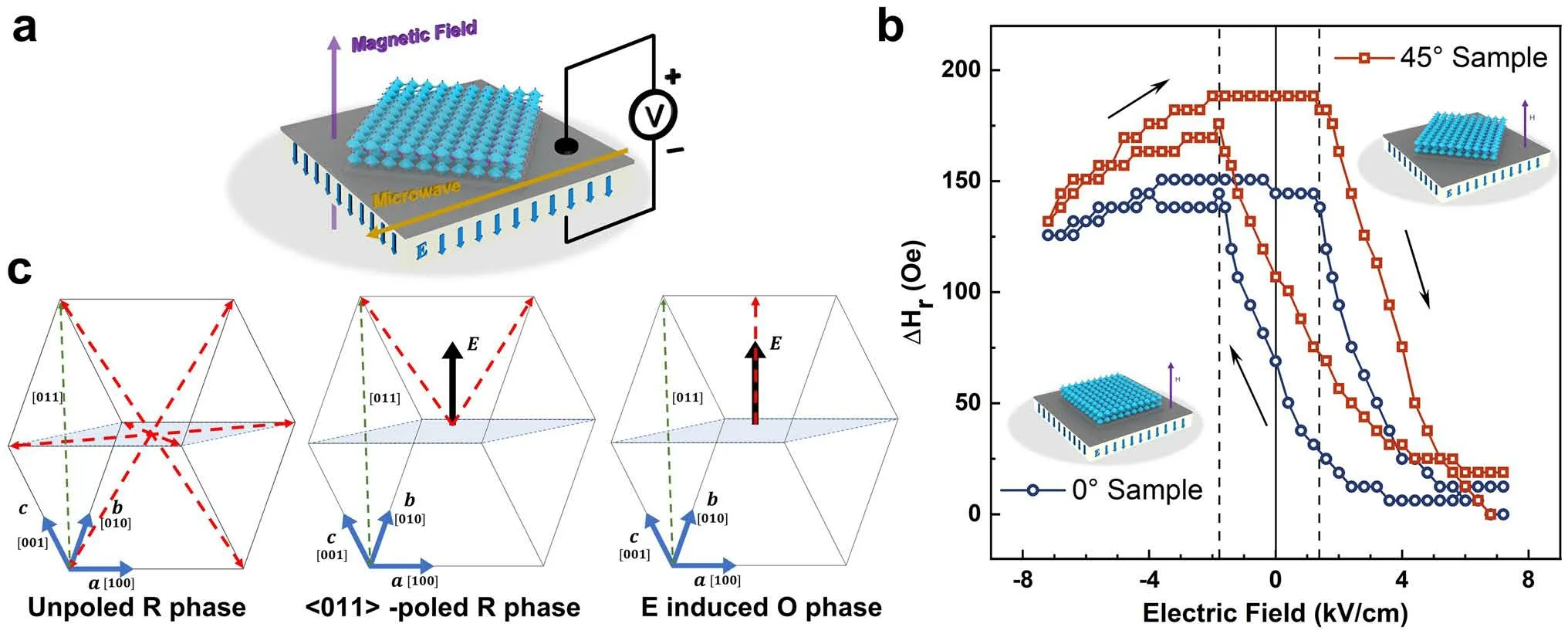
Fig.3 a Schematic diagram of FMR measurement with an applied bipolar electric field, the magnetic field points out of the plane.b Out-ofplane resonance field (Hr) as a function of electric field (E) for 0° Sample (blue) and 45° Sample (red).c Polarizations of the PMN-PT (011)substrate upon applying an electric field along the [011] direction.The red arrows represent the polarization directions for the rhombohedral (R)and orthorhombic (O) phases
3.4 Electric Field Control Magnetic Anisotropy of LSMO/PMN-PT
To further explore the in-plane magnetic anisotropy switching, a 7.2 kV cm-1electric field is applied when measuring the in-plane angle-dependent magnetization of the LSMO/PMN-PT heterostructures.In Fig.4a, b (gray line), theMr/Msplot after the transfer process for both 0° and 45° Samples exhibits a slight fourfold anisotropy with two magnetic easy axes LSMO [110] and LSMO [-110].This fourfold anisotropy in transferred LSMO film originates from the incomplete release of the biaxial epitaxial tensile strain [21,36].When the electric field is applied, a large compression strain along the PMN-PT [100] is induced.Thus, the fourfold anisotropy ofMr/Msswitches to the uniaxial anisotropy with an easy axis toward LSMO [100] for 0° Sample, as shown in Fig.4a.However, for the 45° Sample, the twist angle between the constituent layers conduces to a different in-plane magnetic anisotropy, as shown in Fig.4b.In this case, the easy axis appears atφH= 45°, coinciding with tensile strain and a positive magnetostriction coefficient of LSMO.However, the hard axis is alongφH= 160°, which indicates a complex lattice distortion induced by different strain modes.
Figure 4c exhibits the normalized M-H loops of easy axis (φH= 0°) and hard axis (φH= 90°) for 0° Sample.The squarenessMr/Msdramatically decreases from 0.88 to 0.29 with coercivity synchronously reducing from 72.6 to 25.1 Oe when in-plane magnetic field angular (φH) changes from 0° to 90°.Meanwhile, the coercivity field displays a similar angle-dependent feature withMr/Msas shown in(Fig.S4).The normalized M-H loop also exhibits a different magnetization feature for 45° Sample.When the magnetic field direction changes from easy axis (φH= 45°) to hard axis(φH= 160°), theMr/Msreduces from 0.87 to 0.53 with the coercivity field changing from 40.6 to 36.1 Oe.The differences of the magnetic anisotropy and magnetization feature at the electric field between the two samples further indicate the novel strain-induced magnetoelastic effect in the LSMO/PMN-PT heterostructures.
To further investigate the changes in magnetic anisotropy,the ferromagnetic resonance method is used.(The fitting method is shown in Note S1.) The schematic diagram of the coordinate system is shown in Fig.5a, where the azimuth of spontaneous magnetizationMand external magnetic fieldHwith respect to the sample surface is marked asθM,φM,andθH,φH, respectively.The out-of-planeHranisotropy for the two samples is not significantly different under+ 7.2 kV cm-1, as shown in Fig.5b, which indicates that the twist angle does not cause magnetization reorientation in out-of-plane direction.The fourfold magnetic anisotropy is observed in transferred films with easy axis along LSMO[110] and hard axis along LSMO [-110], as shown in Fig.5c,d (gray).Fitting results demonstrate a dominant fourfold anisotropy effectiveHf, since the fitting values ofHu= 14 Oe andHf= 33 Oe, which can be attributed to the incomplete release of epitaxial strain and the magnetocrystalline anisotropy of LSMO [27, 37].
After applying an electric field of + 7.2 kV cm-1, the 0°Sample changes to a uniaxial magnetic anisotropy with the easy axis along LSMO [100] and hard axis along LSMO[010], showing a dumbbell-like curve with fitting valuesHu= 120 Oe andHf= 5 Oe, as shown in Fig.5c.However, in the 45° Sample, fitting values ofHu= 68 Oe andHf= 55 Oe imply the coexistence of fourfold and uniaxial anisotropy in 45° Sample.The two different easy axes point toφH= 45° (LSMO [110]) andφH= 140°, while a strong hard axis is alongφH= 100°, as shown in Fig.5d.The termHurefers to the magnetoelastic energy, which describes the uniaxial stress anisotropy due to piezoelectric strain from the substrate [38, 39].For LSMO with a positive magnetostriction coefficient, the easy axis occurs along the tensile stress direction or perpendicular to the compressive stress direction.In 0° Sample, the compressive stress acts on LSMO [010] and tensile stress acts on LSMO [100].Thus,as electric field applied, LSMO film displays a uniaxial magnetic anisotropy with LSMO [100] easy axis.In 45°Sample, the 45° twist angle causes the compressive stress to act on the LSMO [-110] (φH= 135°), while the tensile stress acts on the LSMO [110] (φH= 45°).Therefore, the uniaxial magnetic anisotropy rotates 45° and easy axis points to LSMO [110], due to the twist angle.Besides, this twist angle causes aφf= 28° phase shift between uniaxial stress anisotropy and fourfold magnetocrystalline anisotropy, which explains the new type of magnetic anisotropy in 45° Sample.This result further indicates that, by the twisted integration, the specific substrate’s piezoelectric strain can produce a twist angle-dependent magnetic anisotropy in the magnetic films.This twist angle degree of freedom could help to discover new physical phenomena in artificial magnetoelectric heterostructures.
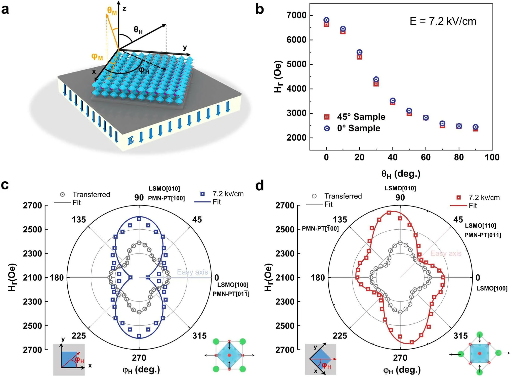
Fig.5 a Schematic diagram for polar coordinates of external magnetic field and spontaneous magnetization.The x-axis and the y-axis are parallel to the LSMO [100] and [010], respectively.b Out-of-plane (θH = 0°) angle-dependent FMR of 0° sample and 45° sample at 7.2 kV cm-1.c,d In-plane Hr anisotropy of the transferred and stress film at 7.2 kV cm-1.Points are test data; lines are fitted data.The substrate orientation is fixed, and the schematic diagram of in-plane structure and lattice distortion is shown below the plot
4 Conclusions
In summary, we applied the epitaxial lift-offtechnique to stick the epitaxial (001)-oriented LSMO ferromagnetic films onto the (011)-oriented PMN-PT ferroelectric substrates with different twist angles.Due to the 45° twist angle between LSMO and PMN-PT, the biaxial strain from PMNPT acts on the LSMO layer in different modes, resulting in the coexistence of uniaxial and fourfold in-plane magnetic anisotropy.This twist integration method provides tunability of the twist angle between different layers, allowing a new degree of twist freedom.This study demonstrates the twist angle degree of freedom for performance regulation in magnetoelectric heterostructures and confirms the great research potential of twist angle-adjustable through epitaxial lift-offtechnology.
AcknowledgementsThis work was supported by the National Key Research and Development Program of China (Grant No.2021YFB3201800), Natural Science Foundation of China (Grant Nos.U22A2019, 91964109, 52372123), State Key Laboratory for Mechanical Behavior of Materials (No.20222405), Innovation Capability Support Program of Shaanxi (Grant No.2021TD-12)and National 111 Project of China (B14040).The authors would like to thank the support from the Instrumental Analysis Center of Xi’an Jiaotong University.
FundingOpen access funding provided by Shanghai Jiao Tong University.
Declarations
Conflict of interestThe authors declare no interest conflict.They have no known competing financial interests or personal relationships that could have appeared to influence the work reported in this paper.
Open AccessThis article is licensed under a Creative Commons Attribution 4.0 International License, which permits use, sharing,adaptation, distribution and reproduction in any medium or format,as long as you give appropriate credit to the original author(s) and the source, provide a link to the Creative Commons licence, and indicate if changes were made.The images or other third party material in this article are included in the article’s Creative Commons licence, unless indicated otherwise in a credit line to the material.If material is not included in the article’s Creative Commons licence and your intended use is not permitted by statutory regulation or exceeds the permitted use, you will need to obtain permission directly from the copyright holder.To view a copy of this licence, visit http:// creat iveco mmons.org/ licen ses/ by/4.0/.
Supplementary InformationThe online version contains supplementary material available at https:// doi.org/ 10.1007/s40820- 023- 01233-z.
- Nano-Micro Letters的其它文章
- Multiphase Interfacial Regulation Based on Hierarchical Porous Molybdenum Selenide to Build Anticorrosive and Multiband Tailorable Absorbers
- Atomic Dispersed Hetero-Pairs for Enhanced Electrocatalytic CO2 Reduction
- Artificial Intelligence Meets Flexible Sensors:Emerging Smart Flexible Sensing Systems Driven by Machine Learning and Artificial Synapses
- Structural Isomers: Small Change with Big Difference in Anion Storage
- Engineering Strategies for Suppressing the Shuttle Effect in Lithium-Sulfur Batteries
- Intelligent Recognition Using Ultralight Multifunctional Nano-Layered Carbon Aerogel Sensors with Human-Like Tactile Perception