
Fluid-chemical modeling of the near-cathode sheath formation process in a high current broken in DC air circuit breaker
2024-01-25 07:13:52ShiDongPeng彭世东JingLi李静WeiDuan段薇YunDongCao曹云东ShuXinLiu刘树鑫andHaoHuang黄浩
Chinese Physics B 2024年1期
Shi-Dong Peng(彭世东), Jing Li(李静), Wei Duan(段薇), Yun-Dong Cao(曹云东),Shu-Xin Liu(刘树鑫), and Hao Huang(黄浩)
Key Laboratory of Special Electric Machine and High Voltage Apparatus(College of Electrical Engineering),Shenyang University of Technology,Shenyang 110870,China
Keywords: near-cathode sheath, atmospheric pressure air arc, fluid-chemical model, high current, DC air circuit breaker(DCCB)
1.Introduction
An atmospheric air arc is a high-density plasma that is generated when a DC air circuit breaker (DCCB) interrupts the current.[1]DCCB is now developing towards extinguishing the arc more effectively and rapidly,so the arc needs to be stretched rapidly when generated in the DCCB.[2]Metal splitter plates are usually used in a DCCB to extinguish the arc,whose principle is to cut the arc into series of sub-arcs through the splitter plates.The voltage drop of the near-electrode sheath formed by the sub-arcs can increase the arc voltage to the supply voltage, so that the arc is extinguished.[3]The near-electrode sheath can affect arc behavior and make the arc root hop, which affects the process of arc stretch.[4]In addition, the near-electrode sheath is the connection between the arc column and the electrode, and the heat and current transfer between the arc and the electrode is completed through the near-electrode sheath.The formation of the near-electrode sheath is an important problem for almost all plasmas, and it is one of the problems that has not been fully recognized.Therefore,an in-depth understanding of the arc sheath formation process can provide a method for energy regulation at the preliminary stage of the arc in DCCB.It can also be used as a prerequisite for studying the arc splitting and arc voltage raising process in DCCB,which provides theoretical guidance for rapidly interrupting DCCB.
As part of the connection components between the arc column and the electrode, the sheath significantly affects arc behavior.[5,6]The current is transferred through the sheath to the arc column to maintain arc combustion,which affects the energy distribution in the arc.The arc energy is transferred to the electrode through the sheath, which increases the electrode’s surface temperature and alters the electron emission law of the cathode.[7–9]At present, there are two main microscopic mathematical descriptions of the sheath in highpressure arc discharge.The first is a unified description.In this method, the arc column and sheath are described by the same governing equations, and the heat and current transfer between the arc and the electrode is considered.This method requires a large amount of computing resources and when a unified model is used it is usually necessary to modify some governing equations to get better agreement with experimental results.[10–15]In the second,the arc column and sheath are described separately,that is,different governing equations for local thermal equilibrium(LTE)arc column and non-local thermal equilibrium (non-LTE) sheath are used, which requires elaborate mesh division and large computing resources, so the requirement of solving accuracy is relatively high.[16–19]With these two modeling methods, researchers have obtained significant parameters of voltage drop, electron number density and voltage–current characteristics,[20]electron and ion number density,[21,22]and electron temperature[21,23]of the sheath.Benilovet al.established a model to describe the arcsheath-electrode heat transfer.The attachment modes of two kinds of arc roots on the electrode were found (i.e., defuse mode and spot mode),[24–28]and the differences between the one temperature model and the two-temperature model were compared.[29]Cejaset al.simulated the transition from atmospheric air glow discharge to arc discharge by a fluid model.[20]Baevaet al.simulated a low current arc discharge with argon gas with an improved one-dimensional unified fluid model.[14]Up to now, although numerical research can well predict the heat transfer and voltage drop of arc sheath, the models that are used are mostly steady state, so our understanding of the transient process of sheath formation and the complex chemical reaction kinetics in the sheath formation process is still insufficient.The chemical reaction kinetics and particle behavior between electrodes at the moment of arc generation can be analyzed by simulation, which can provide a theoretical basis for further study of arc stagnation on electrode and electrode ablation in the preliminary arc.
Due to the small dimensions of the sheath space,an inner sheath with a large physical field gradient,and the highly transient formation process of the sheath,it is difficult to measure sheath parameters directly in the experiment.[15,30]In particular, the high current arc has a high luminescence intensity,and hence the frequently-used plasma detection methods such as absorption spectrum and laser-induced fluorescence are no longer suitable for the detection of arc plasma.At present,the experiments on plasmas, including spectral diagnosis,[31,32]Langmuir probe[33]and high-speed imaging,[34,35]and so on are mostly focused on low density plasmas.The formation process of high current arc sheath lasts only tens of microseconds, and it is also difficult to observe the emission spectrum due to the limitation of the sampling rate of the spectrometer.The fluid-chemical model can solve the transient equations that describe the convection and diffusion of plasma particles/energy,which provides a new method to solve the above problems.[36]In recent years, dielectric barrier discharge (DBD),[37,38]corona discharge,[39,40]glow discharge,[11]partial discharge of insulating materials,[41]and plasma surface modification[42]have been studied with the fluid-chemical model, all of which are low density plasmas.The fluid model was established to study argon arcs at low or atmospheric pressures by Baeva and Benilovet al., which are all steady-state models.[14,27,43]For the transient arc sheath formation process, by assuming that the sheath is a nonlinear resistance,the arc extinguishing performance of DCCB is studied in Ref.[44].Although this hypothesis truly reflected the properties of the sheath voltage drop,the process of sheath formation, which is determined by the motion of the particles and the space charge distribution,was not analyzed in the model.As the capacity of the distribution network has expanded in recent years, the capacity of DCCB has gradually expanded and the voltage has risen to the medium-voltage.When the high current arc is interrupted in medium-voltage DCCB, the arc energy is high, and therefore dissipating the arc energy quickly, and realizing fast and effective currentlimiting interruption becomes harder.During the arc formation process,electron impact ionization is the main ionization mode between the electrodes.The cathode, as the emitter of electrons, has a more crucial role than the anode in the arc formation process.Therefore,an in-depth investigation of the formation process of the cathode sheath of the high-current arc can provide theoretical support for the initial energy regulation of the arc when medium-voltage DCCB interrupts the high current and the arc energy generated at the preliminary stage can be reduced effectively, which can lay a good foundation for effective and rapid interruption.Given that the high-current air arc in DCCB is a high-density plasma, particle collisions are intense in the early arc formation process,which is a highly transient process.In addition,many species are involved in air arc discharge,which makes reactions complex,and so the model needs elaborate mesh generation,which makes modeling difficult.Therefore,there are hardly any simulation studies involving the transient fluid-chemical model of an air arc.
The magneto-hydro-dynamic(MHD)model was used in Ref.[45], which is a kind of macroscopic model.The MHD model can describe the arc’s morphology through temperature field distribution but ignores the arc’s generation process.The fluid-chemical model adopted in this work is a kind of microscopic model,whose purpose is to simulate the arc generation process (cathode-sheath formation process) which cannot be considered sufficiently in the MHD model.To study the arc formation process further, in this work the medium-voltage DCCB (whose structure and working principle have been introduced in Ref.[45]) is taken as the research object and a fluid-chemical model considering the main reactions during the arc generation process is established.In contrast to the previous steady-state model,a transient solution is adopted in the fluid-chemical model used in this work and the electron emission boundary of the cathode is treated carefully, so that the model can simulate atmospheric pressure air arc discharge accurately.Using this model, the transient changes of electrons, ions, and electric fields during the formation process of the cathode sheath when medium-voltage DCCB interrupts different high currents are focused on in this work.The effects of different homogeneous external magnetic fields on the nearcathode sheath are also investigated.In this work, the physical model and mathematical description of the arc formation process are introduced in Section 2 and model verification is given in Section 3.The physical process of arc formation,including the formation process of the sheath and the evolution law of arc plasma between electrodes by taking 20 kA current interrupting as an example,are studied in Subsection 4.1.The variation law of plasma parameters between sheath and electrode when different high currents are interrupted is studied in Subsection 4.2.The influence of different homogeneous external magnetic fields on the near-cathode sheath is studied in Subsection 4.3.Finally, Section 5 gives the conclusions and outlook for future work.
2.Models
2.1.Physical model
When the contacts separate in a DCCB,the cathode emits electrons into the electrode gap under the action of the strong electric field.The electrons then move towards the anode under the action of the electric field and continuously impact with the neutral particles, ionizing to give positive ions and new electrons.After the electrons arrive at the anode and are absorbed by the anode,positive ions arrive at the cathode surface and the cathode sheath begins to form.
Figure 1 shows the structure of the arc and the nearcathode sheath during the arc discharge.The arc can be divided into three parts: the near-cathode sheath, the arc column,and the near-anode sheath.Usually,quasi-neutral conditions are used to define the edges of the space charge layer and the pre-sheath layer.In our numerical simulation, according to the theory proposed by Tonks and Langmuir,[46]combined with the criteria given by Franklin,[47]the sheath location with(ne+nn)/np=0.99 is considered to be the boundary between the space charge layer and the pre-sheath layer.ni>nein the space charge layer,and 0.99≤(ne+nn)/np≤1.01 in the presheath layer.Wherene,npandnnare the electron number density, positive ion number density, and negative ion number density, respectively.There is a voltage drop in the nearcathode and anode sheath,and the voltage drop of the arc column in the short-length arc is very small compared with that in the sheath.In the early arc formation process, the cathode sheath has an important effect on electron emission and electron impact ionization is the main ionization mechanism in the early arc formation process.Therefore,the cathode’s activity has a significant influence on the energy distribution during the process of arc formation.Starting from the cathode’s surface, the cathode sheath can be divided into three parts: the space charge layer, the ionization layer, and the thermal nonequilibrium layer.Most importantly, electron emission from the cathode surface plays a crucial role in these layers.In Fig.1, the thickness of the space charge layer, closest to the cathode, is about a few micrometers.In this layer, the quasineutral condition is no longer applicable and the voltage drop near the cathode is formed in this layer.Due to the acceleration of the strong electric field in this layer,the electrons enter the ionization layer after getting enough electron energy.In the ionization layer,high-speed electrons and neutral particles collide and ionize,generating positive ions and new electrons.The number density of positive ions multiplies and the electron density increases accordingly.This layer maintains the continuity of arc current and the thickness of the ionization layer is generally about tens of micrometers.Electrons pass through the ionization layer under the action of electric field and come to the thermal non-equilibrium layer, which is the closest to the arc column.The thermal conductivity of electrons is not equal to that of heavy ions, and the temperature of the electrons is still higher than that of the heavy ions.This layer maintains the continuity of arc heat transfer,and its thickness is tens to hundreds of nanometers.The electron enters the arc column through the thermal non-equilibrium layer.The center of the arc column(arc core)satisfies the condition of LTE but the edge of the arc column(arc periphery and arc plume)still deviates from the LTE condition.[48]This work focuses on the physical process of the near-cathode sheath.In the simulation and analysis,the near-cathode sheath is divided into the space charge layer and the pre-sheath layer.A more detailed classification of the pre-sheath layer, i.e., the subdivision of the ionization layer and the thermal non-equilibrium layer,will be considered in our future research.
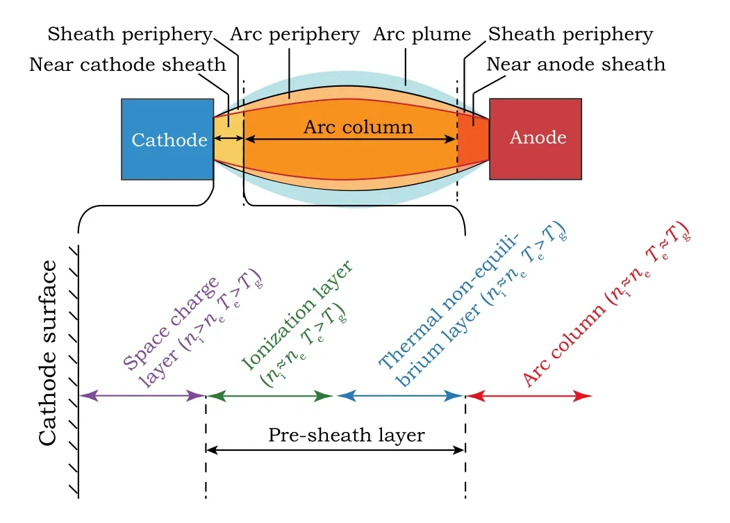
Fig.1.The structure of the arc and near-cathode sheath in atmospheric air arc discharge.
2.2.Mathematical model
2.2.1.Geometric model and basic assumptions
The two-dimensional axisymmetric model established in this work is shown in Fig.2, and the radius (BC and AD) of the contact is 10 mm.Due to the presence of N2, O2and noble gases in the air, complex physical and chemical processes occur between the electrodes in the process of air arc discharge.[49]Considering that an air arc discharge will produce a trace amount of O3,which will corrode the shell of the circuit breaker and according to Ref.[50],the air is simplified as a mixture that consists of 78%N2,21%O2,and 1%O3in this work and 16 kinds of species,46 gas reactions,and eight surface reactions were introduced.As the movement of electrons and ions in the electric field forms the arc current at the initial moment of arc formation, the arc current is in a quasisteady state.[51]Therefore, the current applied in this simulation does not change with time.Since the electrodes are in the dynamic process of small separation distance,the contact displacement within the simulation duration time (10000 ns) is very short.To avoid huge computation, the movement of the contact is ignored in this work and we assume that the contact separation has reached a fixed length.The effect of the arc self-generated magnetic field is also ignored.Because the near-cathode sheath formation process is very short,the effect of arc heating on the electrode and Joule heating generated by the current in the electrode are not considered here.

Fig.2.(a)The physical process between electrodes in the early arc formation process;(b)the geometric model of the simulation.
In the early arc formation process, the number density of the particles is determined by convection, diffusion, and chemical reactions.[52]Therefore,the mathematical model established in this work includes the electron continuity equations for solving the electron number density distribution,the electron energy conservation equations for solving the electron energy distribution,and the heavy particle migration/diffusion equations for solving the number density distribution of ions,excited particles,and other neutral particles.The above equations are self-consistent by coupling the Poisson equation to solve the electric field distribution.In addition, since photoionization does not play a significant role during the arc formation process, and the calculation amount is huge if photoionization is considered.[53]Therefore, photoionization is not considered in the model and the initial electron density of uniform spatial distribution is set to 1×10¹³m−3.Since the electron mean free path is much smaller than the electrode gap,the arc and near-cathode sheath formation process can be described by a fluid method.[54]
2.2.2.Electron transport equations
The electron number density conservation equation,electron energy density conservation equation, and electron momentum conservation equation are obtained by solving the electron continuity equations[38,54–57]
wherenεis the electron energy density;meis the electron mass;pe=nekBTeIis the electron pressure tensor;tis the time;uis the mass averaged fluid velocity;Iis the unit matrix;Eis the electric field intensity;Qis the external heat source;Qgenis the generalized heat source;Reis the electron source term;Senis the energy loss or gain due to inelastic collisions;νmis the momentum transfer frequency; andΓeandΓεare the electron flux and electron energy flux, respectively.The electron diffusion coefficientDe,electron energy migration rateµε, and electron energy dissipation rateDεare calculated using Einstein’s relation,respectively.De=µeTe,µε=(5/3)µe,Dε=µεTe.Teis the electron temperature;µe=e/meveis the electron mobility; andeis the elementary charge.
Poisson’s equation is used to solve the potential distribution
whereε0is dielectric constant in vacuum;εris the relative permittivity;andρvis the local charge density.
The drift velocity of the electronsueare denoted as
whereνeis the collision frequency between the electrons and neutral particles;Tgis the gas temperature;andkBis the Boltzmann constant.
The electron flux and electron energy flux are given by
The electron transport properties can be calculated by the electron energy distribution function(EEDF),[58]as shown below:
whereµeNnis the reduced electron mobility;DeNnis the reduced electron diffusivity;µεNnis reduced electron energy migration rate;DεNnis the reduced electron energy diffusivity.εis the electron energy.σmis the total momentum collision cross section;is a constant;andF(ε)is EEDF.The mean electron energy ¯ε=nε/ne.
The rate coefficient calculated using the cross-section data is a highly nonlinear function of the average electron energy[58]
whereσkis the cross-section of reactionk.
2.2.3.Migration/diffusion equations of heavy particles
Because of the high pressure and large ionization degree of high-current arc plasma, the influence of multi-component diffusion on arc plasma should be considered in the simulation.Therefore, the traditional Fick’s law is replaced by the heavy particles migration/diffusion equations considering multi-component diffusion,as shown below:
wherek=1,2,...,Qspecies,j=1,2,...,Nreactions are assumed,Rkis the mass fraction of thekth heavy particles; according to the composition of the air and the hypothesis conditions in this work, the initial mass fraction of N2, O2, and O3are set as 0.78,0.21,and 0.01 respectively.Mnis the mean molar mass;zkis the charge number for speciesk;jkis the diffusive flux vector;ρis density of the gas mixture;µk,mis the mixture averaged mobility for speciesk;andωkis the mass fraction for speciesk.
For speciesk, the average diffusion coefficientDkof the mixture is
whereDk jis the binary diffusion coefficient between specieskandj; andxjis the mole fraction of the target species for reactionj.
The reaction rate depends on the order of the reaction and the molar concentration of each species.The rate expressionRkis determined by the stoichiometric ratio of the system
wherevk jis the stoichiometric matrix;rjis the reaction rate corresponding to the reactionj; andMkis the molecular weight.
The time interval of plasma transition from nonequilibrium state to equilibrium state is called the relaxation time,which is realized by particle collisions.To calculate the collision frequency, the relation between the relative velocity and the collision cross section should be considered, and we need to find the average in the velocity space.[59]Therefore,within the range of usual plasma parameters,the electron–ion collision frequency is shown as, where lnΛis the Coulomb logarithm.In this work, since each gas phase reaction has a different reaction rate, and the reaction rates of some gas phase reactions are a function related to the electron temperature, a simplified formula is adopted to deal with the electron–ion collision frequency:
whereceis the electron molar concentration.
2.2.4.Boundary conditions
The boundary conditions of the electrons, ions, and excited particles are given by
The electron energy boundary condition is given by
whereniandnmare ion number density and metastable number density, respectively.Tiis the ion temperature;γiis the secondary electron emission coefficient; andΓiandΓmare the ion flux and metastable particle flux, respectively.αsandα'sare the step function of the electric fieldEand the normal vectorn
The self-bias potential of the lateral insulation surface is given by
whereD1andD2are the electric displacement field on two sides of the interface;JeandJiare the electron current density and ion current density, respectively.ρsis the surface charge density;n·Jiis the normal component of the total ion current density on the wall andn·Jeis the normal component of the total electron current density on the wall.
When the electrode is in the high temperature and high electric field, thermionic emission and field emission will be generated on the cathode’s surface.[60]The thermionic emission will occur from the micro-spots on the cathode when the cathode surface temperature is higher than 103K,[61]and field emission will occur when the electric field near the cathode surface is greater than 108V/m.[62]Murphy[63]and Christov[64]provided a theoretical derivation of the relationship between current density and the electron flux emitted by the cathode.Christov and Vodenicharov provided an experimental verification of the relationship between the current density and the electron flux emitted by the cathode in the high temperature and high electric field.[65]In this work,according to the research of Murphy and Christov,it is assumed that electrons are emitted from the cathode spots accumulation area.According to the Richardson–Dushman equation,the electron emission boundary conditions of the cathode spots accumulation area are given as follows:
whereJis the current density;Mis the constant;his the Planck constant;Tcis the temperature of cathode surface;Wis the escaping work caused by an external electric field;W0is work function;Esis electric field on contact surface;andfis field enhancement factor.After the liquid metal bridge ruptures,the temperature of the micro-spot on the cathode surface is between the melting point(1357.8 K)and the boiling point(2835 K) of pure copper.[66]The temperature of the cathode spots accumulation area is considered to be constant due to the extremely short time scale (microsecond) during the arc formation process.According to Refs.[66,67],Tc=2000 K was taken in this work.In this work, the effect of the microprotrusion on the breakdown at the contact surface is not considered,so the field enhancement factorfis set to 1.
In the simulation,the gas pressure is set to 1 atm(1 atm=101.325 kPa).The boundary conditions that are used in the model are summarized in Table 1.The 16 species (particles)considered in the model are shown in Table 2.The gas phase reactions and surface reactions considered in the model are shown in Tables 3 and 4,respectively.
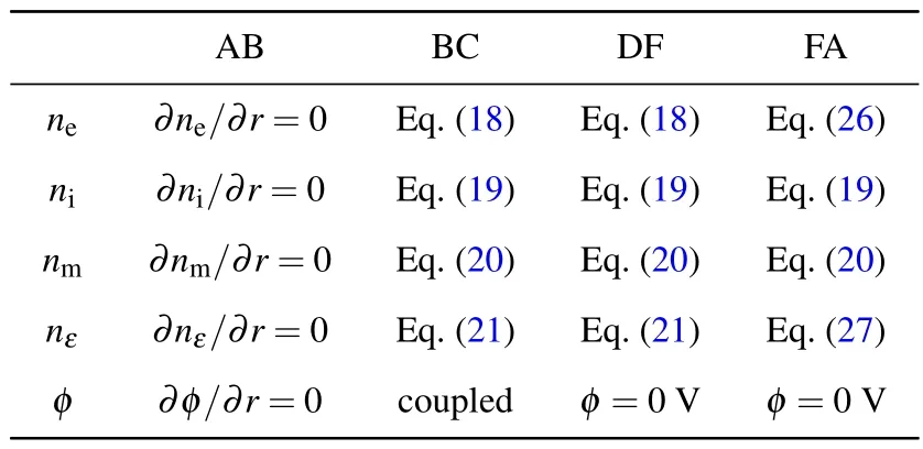
Table 1.Boundary conditions used in the model.
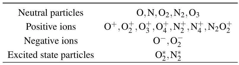
Table 2.The particles considered in the model.
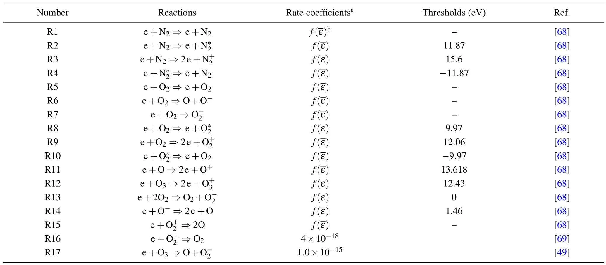
Table 3.The gas phase reactions considered in the model.
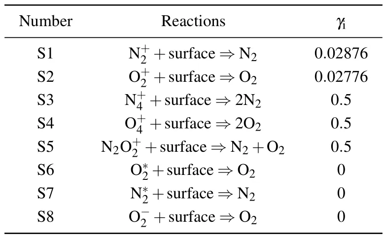
Table 4.The surface reactions considered in the model.
2.3.External circuit setup
In this work, an RC series external circuit is set to keep the discharge current constant.The external circuit is shown in Fig.3, and the external circuit is connected with the arc plasma computing domain.The capacitanceCbis set as 0.1 pF to make the current in the arc plasma computing domain rise smoothly,and the numerical stability at the initial moment of the simulation can be improved.
2.4.Meshes and convergences
The division of the mesh is of vital importance for the accurate solution of the model.The mesh can be considered to meet the requirement of solving accuracy by refining the mesh continuously until the solution results do not change with the mesh refinement.
To reduce the amount of calculation and ensure the accuracy of the computational results,the model is divided into two mesh subdivision regions, ABEF and CDFE, as shown in Fig.2(b).ABEF is the region where particles impact violently and the encrypted mesh is used in this region because the mean free path of electrons in high-pressure arc discharge is extremely short.Therefore, the maximum size of the free triangle mesh adopted in the model is 0.6 µm, the minimum size is 0.1 µm, and the maximum mesh growth rate is 1.1.CDFE is the region where partials impact non-violently.The maximum size of the free subdivision triangular mesh is 4µm and the minimum size is 0.1µm,the maximum mesh growth rate is 1.05.
The simulation is carried out through COMSOL Multiphysics 6.0®commercial software.[72]To ensure the calculation accuracy and improve the convergence of the model,the PARDISO solver[73]is used,and the backward difference method is adopted for time stepping.The computational duration of every simulation is less than 50 hours on the EPYC 7713 platform with 128 GB memory.
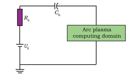
Fig.3.RC series external circuit.
3.Model validation
To verify the effectiveness of the model, a simulation model consistent with Ref.[74]was established, as shown in Fig.4(a).The anode and cathode are cylindrical;the diameter of the electrode is 1 mm;the separation of the electrode is fixed to 3 mm;the arc medium is air with 1 atm pressure;the anode voltage is 8 kV and the cathode is grounded; and the arc current is 0.8 kA.The electron number densities along the radial sampling transversals obtained by experiment and simulation are shown in Fig.2(a).The electron number densities of each sampling transversal at 10000 ns measured by the experiment are shown in Fig.4(b).The electron number densities of each sampling transversal at 10000 ns in the simulation model that are consistent with Ref.[74]are shown in Fig.4(c).It can be seen from Figs.4(b)and 4(c)that the simulated arc column radius is a little larger than the measured result because there is a high-current density in the arc discharge and the self-generated magnetic field generated by the arc current plays an important role in arc force.The radial Lorentz forcegenerated by the self-generated magnetic field on the arc plasma points to the interior of the arc and tries to pinch the arc to a smaller diameter.This phenomenon is called a Bennett pinch.[75]Therefore,the arc column shrinks due to the arc selfgenerated magnetic field.In our simulation,without considering the self-generated magnetic field,the arc column radius is slightly larger than the measured one.The electron number density distribution obtained by simulation presents a Gaussian distribution and the simulation result of electron number density at the axis is 4.69×10²³(y=1.2 mm), 3.32×10²³(y=0 mm),7.19×1023(y=−1.2 mm).While the measured result is 4.75×10²³(y=1.2 mm), 3.05×10²³(y=0 mm),6.70×1023(y=−1.2 mm)Therefore,the simulation and experimental results have a good agreement, which proves the validity of the simulation model.
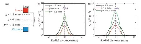
Fig.4.Numerical model validation.(a) The geometric model, the tungsten electrode contact separation is 3 mm, the arc medium is air with 1 atmosphere pressure, the anode voltage is 8 kV and the cathode is grounded, and the arc current is 0.8 kA.(b) Experimental measurement results.[74] (c)Simulation results.
4.Simulation results and analysis
4.1.The formation process of a near-cathode sheath with 20 kA arc current
In this section, a 20 kA DC short-circuit current interrupted in the medium-voltage DCCB is taken as an example to investigate the arc plasma behavior between electrodes and the near-cathode sheath formation process.
Figure 5 shows the evolution process of electron number densityneand ion number densityniwhen the 20 kA current is interrupted.Before the arc conducting path is established,field emission at the cathode surface is the main electron emission mechanism.After the arc conducting path is established,thermionic emission at the cathode surface is the main electron emission mechanism.During the arc formation process and arc combustion,electron impact ionization is the main ionization mechanism and is also the main means of positive ion generation between electrodes.It can be seen from Figs.5(b)–5(i)that at 1 ns,under the action of the electric field,electrons are emitted from the cathode’s surface and move towards the anode, and some electrons impact with the neutral particles between the electrodes,generating positive ions and new electrons.The number density of positive ions between electrodes is multiplying,and some electrons arrive at the anode and are absorbed by the anode.At 2.5 ns,electrons penetrate through the entire electrode gap and the arc column is formed.The ion number density in the arc column reaches the same order of magnitude as the electron number density 1022,the arc column is almost completely ionized,while the ion number density in the periphery of the near-cathode sheath (hereinafter referred to as the pre-sheath layer)is higher than the electron number density.This shows that electrons impact with neutral particles in the pre-sheath layer, and then ionize to generate positive ions and new electrons.With the increase of positive ions generated by the electron impact ionization in the pre-sheath layer,the internal electric field generated by positive ions is reversed with the external electric field,resulting in an increase of the electric field intensity in the near-cathode sheath.Electrons pass through the near-cathode sheath quickly under the strong electric field,so the number density of electrons in the near-cathode sheath is low.At 5.0 ns and 20 ns, the electron and ion number density in the arc column reaches the steady state at the order of magnitudes 1023.At the same time, the electron number density is larger than the ion number density at the outermost arc column.It can be seen that the outermost arc column is not completely ionized, which is called an arc plume in Ref.[48].After 20 ns, the electron number density and ion number density begin to decrease slowly because of the broadening of the arc column.At 500 ns, positive ions with slow velocity compared with electrons pass through the near-cathode sheath and reach the cathode’s surface,and positive ions on the cathode’s surface that have not been absorbed by the cathode are still there.At the same time, positive ions impact the cathode’s surface and the secondary electron emission is produced.When the arc reaches the steady state, the electric field intensity on the cathode’s surface reduces,which is not enough to maintain the field emission of electrons on the cathode’s surface.Therefore,when the steady state of the arc is established, the thermionic emission at the cathode surface and the secondary electron emission generated by the positive ions impact the cathode’s surface and maintain arc combustion.
Electron impact ionization is the main ionization mechanism between electrodes during the arc formation process.Figure 6(a) shows the evolution of the electron number density versus time along the axis.The electron number density in the arc column increases first, then decreases, and then increases until it reaches a steady state.Before 5 ns, the electrons emitted from the cathode impact with neutral particles to ionize between electrodes and the electron number density increases rapidly.At 5 ns, the electron number density approaches the order of magnitudes 1022m−3.During 5 ns–500 ns,electrons move to the anode under the action of electric field and are absorbed by the anode,and the electron number density between electrodes decreases gradually.After 500 ns,as positive ions arrive at the cathode, they impact the cathode’s surface and produce secondary electron emission, the cathode’s emission is enhanced,and the electron number density in the arc column increases again,reaches a steady state at 10000 ns, and a free burning arc is formed.Figures 6(b)and 6(c)show the evolution of the positive and negative ion number density,respectively.Positive ions are mainly produced by electron impact ionization, and negative ions are mainly produced by neutral particles absorbing electrons.The positive and negative ion number density in the arc column increases rapidly before 5 ns, and increases slowly until it reaches its steady state between 5 ns and 10000 ns.When the arc reaches a steady state, the number density of positive ions in the arc column is slightly higher than that of negative ions,indicating that the arc column has an electropositive property, which is consistent with the results reported in Ref.[76].In the nearcathode sheath, as shown in Fig.6(a), the electron number density is very low.This happens because a strong electric field in the near-cathode sheath is established due to the positive space charge at the junction between the arc column and the near-cathode sheath.The electrons are accelerated by the strong electric field and the electrons that are emitted from the cathode rapidly leave the near-cathode sheath.Due to the low electron number density and low collision probability in the near-cathode sheath, this region is called a collisionless region in Ref.[21].Therefore, the positive and negative ion number density in this region is low.However, the number density of positive ions in this region is 6–8 orders of magnitude higher than that of negative ions.As shown in Fig.6(d),there is a large amount of net space charge at the junction between the arc column and the near-cathode sheath.As time goes on,the positive space charge number density in the nearcathode sheath also increases,which will lead to the formation of an internal electric field at the periphery of the near-cathode sheath.This internal electric field is opposite to the electric field generated by the external circuit.The electric field reversed region is then formed.It is difficult for positive ions to break through the electric field reversed region to enter the near-cathode sheath and then be absorbed by the cathode.This is the main reason for the accumulation of positive charges and the high number density of net space charges in the periphery of the near-cathode sheath.
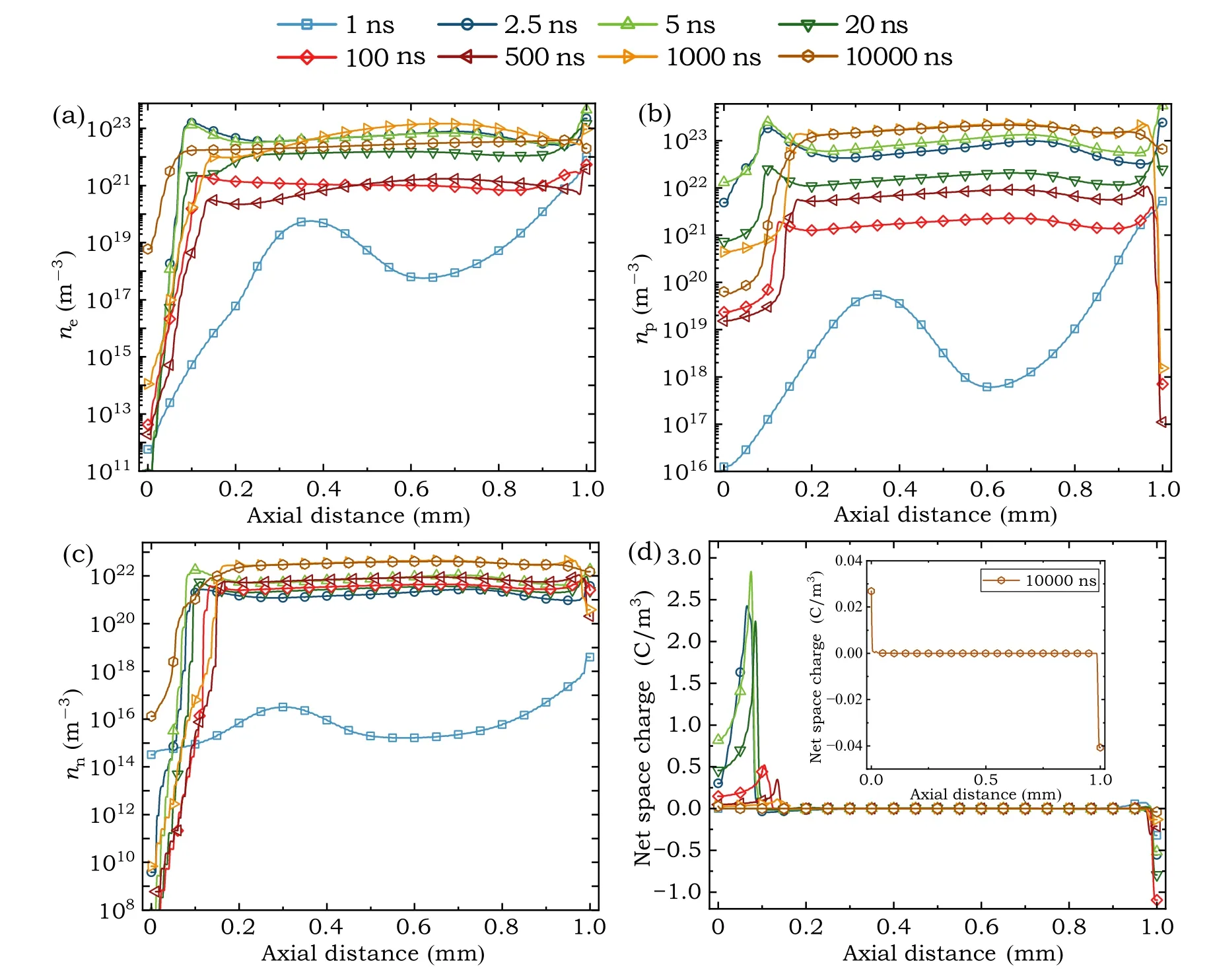
Fig.6.Contact fixed separation 1 mm,arc current 20 kA,discharge pressure 1 atm.The x-coordinate of 0 mm represents the cathode’s surface,and the x-coordinate of 1 mm represents the anode’s surface.(a)Electron number density along the axis;(b)positive ion number density along the axis;(c)negative ion number density along the axis;and(d)net space charge number density along the axis.
Figure 7 shows the electric potential and electric field intensity along the axis versus time.With the development of the arc discharge,the electric potential between electrodes decreases gradually until the electrode gap breaks down.A free burning arc is then formed when the voltage drop in the arc column is almost 0 and the voltage drop in the near-cathode sheath is established.During the establishing process of the near-cathode voltage drop, the value of this voltage drop is 1750 V at 5 ns.Meanwhile, the electrons emitted from the cathode’s surface have already penetrated the entire electrode gap and reached the anode surface.However, the positive ions emitted from the anode have not reached the cathode surface, there is a large electrical barrier in the near-cathode sheath, and the electrode gap has not broken down.Subsequently,the near-cathode sheath voltage drop decreases gradually.At 10000 ns,the voltage drop is 12.33 V,indicating that the electrode gap has broken down and a stable arc discharge is formed.In Fig.7(b), the electric field in the near-cathode sheath is distorted.Before 5 ns,the electric field is distorted in the near-cathode sheath and becomes larger and larger with the development of arc discharge,the distortion degree of electric field reaches its maximum at 5 ns,and the electric field intensity in the near-cathode sheath reaches the order of magnitudes 107V/m.Then,the distorted electric field in the near-cathode sheath decreases gradually and a relatively stable near-cathode sheath voltage drop is established.The collision reaction of particles between electrodes and the velocity difference caused by different particle masses increases the positive charge in the near-cathode sheath, which distorts and increases the electric field intensity in the near-cathode sheath.Because the electron number density at the periphery of the near-cathode sheath(pre-sheath layer)is higher,the collision reaction of electrons in this region is drastic, and so more positive ions are generated.Therefore, the growth rate of the electric field intensity near the cathode is higher than that near the anode.
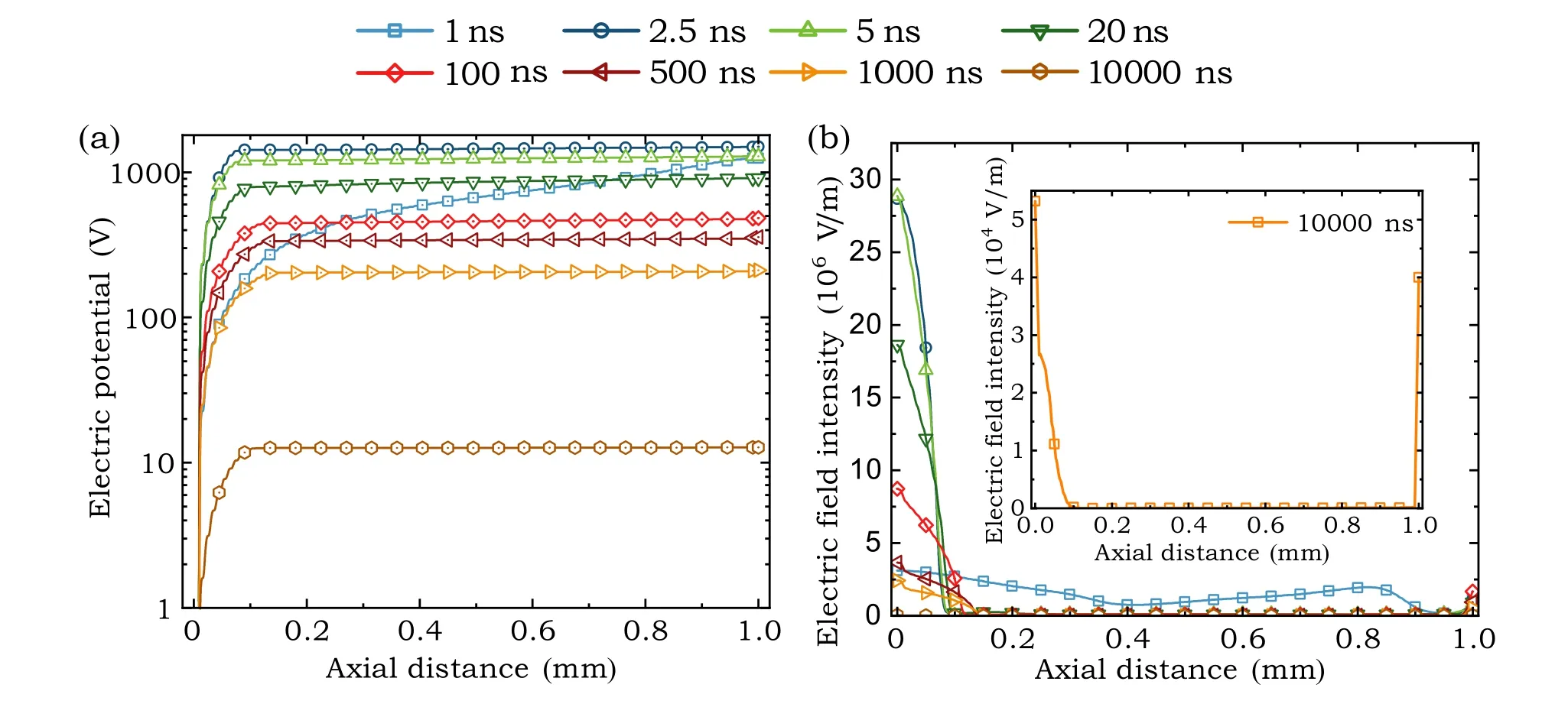
Fig.7.Contact fixed separation 1 mm,arc current 20 kA,discharge pressure 1 atm.The x-coordinate 0 mm represents the cathode surface and the x-coordinate 1 mm represents the anode surface.(a)Electric potential along the axis;and(b)electric field strength along the axis.
Figure 8 shows the distribution of different particles between electrodes along the axis at 10000 ns, only the axial data within 0.5 mm on the cathode surface is extracted for a clearer observation.In Fig.8(a),under the action of the electric field, the positive ions generated by electron impact ionization in the arc column migrate to the near-cathode sheath,those which have not been absorbed by the cathode are the main sources of positive ions.Meanwhile, the negative ions generated by neutral particles adsorbing electrons in the nearcathode sheath are the main sources of negative ions in the near-cathode sheath.Due to the fast movement and the high energy of electrons in the near-cathode sheath,the electron impact ionization happens easily and the adsorption reaction is of low probability to happen.The positive ion number density adjacent to the cathode is 4 orders of magnitude higher than that of negative ions,so the near-cathode sheath is electropositive, which has been referred to as a positive space charge layer in the Ref.[20].The positive ion number density is almost equal to that of negative ions in the arc column, so the arc column is quasi-neutrality.In Fig.8(b), N+2and O+2are the dominant positive ions along the axis.The number density of N+2is slightly higher than that of O+2in the near-cathode sheath and the number density of O+2is slightly higher than that of N+2in the arc column.In the near-cathode sheath, the number density of O+3increases significantly because the generation of O+3is mainly due to the electron impact ionization reaction R12 and the reaction rate of R12 increases significantly at a high electron temperature.[58]The O+3produced at the periphery of the near-cathode sheath migrates to the cathode’s surface under the action of the electric field, resulting in a higher concentration of O+3near the cathode surface.In Fig.8(c), the number density of O−is 6–7 orders of magnitude higher than that of O−2because O−mainly comes from the electron impact ionization reaction R13, while O−2comes from the electron impact ionization reaction R20 and adsorption reaction R42.Since the reaction rate of R13 is much higher than that of R20 and R42, the number density of O−is much higher than that of O−2.As the discharge pressure decreases,the difference between the number density of O−and O−2decreases.[77]
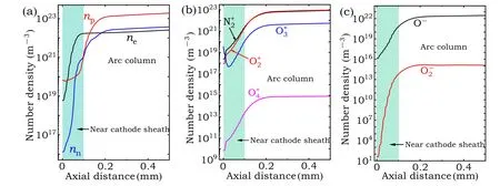
Fig.8.Contact fixed separation 1 mm, arc current 20 kA, and discharge pressure 1 atm.The x-coordinate of 0 mm represents the cathode surface.(a) Electron number density ne, positive ion number density np, and negative ion number density nn distribution along the axis at 10000 ns;(b)dominant positive ions distribution along the axis at 10000 ns;(c)dominant negative ions distribution along the axis at 10000 ns.
4.2.Effect of different current levels on the near-cathode sheath voltage drop
To understand the physical and chemical process between electrodes and the development law of the near-cathode sheath in the early arc formation process when different short-circuit currents are interrupted in medium-voltage DCCB, simulations with short-circuit current levels of 20 kA,40 kA,60 kA,and 80 kA were carried out in this work.The electron number densities between electrodes,net space charge,and voltage drop in the near-cathode sheath during the arc formation process were predicted.
Figure 9 shows the electron number density distribution along the axis with different arc currents at 10000 ns.The electron number density in the near-cathode sheath approaches 0,which is due to the high electric field intensity in the nearcathode sheath.The electrons are accelerated by the electric field,and so they cannot stay in this region.At the junction of the near-cathode sheath and the arc column,the electron number density increases rapidly.In this region,the electrons and heavy particles have a violent impact ionization.In the arc column, the electron number density is at the order of magnitudes 1022, and the higher the arc current is, the higher the electron number density is.In the near-anode region,the electron number density drops sharply, which is due to the rapid absorption of electrons by the anode.In Fig.9,the thickness of the near-cathode sheath is about 0.1 mm(including the space charge layer and the pre-sheath layer),and the thickness of the near-cathode sheath is independent of the arc current.
To further investigate the near-cathode sheath, the net space charge distribution at 10000 ns with different currents on the cathode surface within 0.1 mm along the axis is extracted in Fig.10.The net space charge has a maximum value on the cathode’s surface.Within 0.1 mm on the cathode surface, the net space charge number density decreases with the increase of axial distance, and decreases the fastest within 0.017 mm, which is called the space charge layer.[78]In the range of 0.017 mm–0.095 mm from the cathode surface, the net space charge number density remains relatively stable.In this region,the net space charge is at the order of magnitudes 10−4C/m3with arc currents 20 kA and 40 kA and at the order of magnitudes 10−3C/m3with arc currents 60 kA and 80 kA.This region is usually called the pre-sheath layer.The presheath layer can maintain the continuity of the arc current.In other words, electrons are ionized by impacting with neutral particles in this region after being accelerated by the electric field in the space charge layer.[79]According to this analysis,the thickness of the space charge layer is about 0.017 mm,the thickness of the pre-sheath layer is about 0.078 mm, and the thickness of the two layers is independent of the arc current.
Table 5 shows the near-cathode sheath voltage drop at 10000 ns.The near-cathode sheath voltage drop is 11.14 V at 80 kA and 12.33 V at 20 kA.Reference [80] obtained the near-cathode sheath voltage drop with a copper electrode air arc within the range of 10 V–12 V through experimental observation.The simulation results are in good agreement with the experimental results.The near-cathode sheath voltage drop decreases with the increase of arc current,which is consistent with the trend of the near-cathode sheath voltage drop reported in Refs.[29,81].Therefore, the larger the arc current is, the weaker the current-limiting effect of the splitter plates is,and the more difficult it will be to raise the arc voltage when the arc is split by splitter plates.
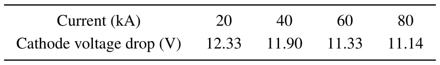
Table 5.Near-cathode sheath voltage drop when different currents are interrupted in DCCB.
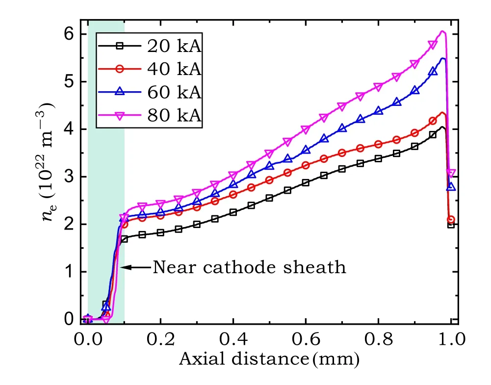
Fig.9.Contact fixed separation 1 mm,discharge pressure 1 atm,the electron number density distribution along the axis with different arc currents at 10000 ns when DCCB is interrupted.The x-coordinate of 0 mm represents the cathode’s surface and the x-coordinate of 1 mm represents the anode’s surface.

Fig.10.Contact fixed separation 1 mm, discharge pressure 1 atm, positive space charge distribution along the axis on the cathode surface within 0.1 mm with different arc currents at 10000 ns when DCCB is interrupted.The x-coordinate of 0 mm represents the cathode’s surface.
4.3.Effect of an external magnetic field on the nearcathode sheath
To achieve fast interruption,the external magnetic field is usually adopted to expel the arc to move along the arc runner in medium-voltage DCCB,which has a great influence on the arc splitting process.The larger the external magnetic field is,the faster the arc movement speed is.However, in the early arc formation process,the external magnetic field has little influence on the arc motion.After the arc is generated between two electrodes, no matter how the external magnetic field increases,the arc will stagnate at the electrodes for a short time,which is called the electrode stagnation of the initial arc.[82,83]In the actual DCCB product, due to the addition of the magnetic plate, the actual magnetic field direction in the product is perpendicular to the transverse plane of the arc chamber, which is considered to be the most favorable magnetic field direction for arc motion.[4]Accordingly,in this work,the magnetic field direction applied is perpendicular to the twodimensional plane in the simulation, with values of 0.01 T,0.02 T,0.03 T,0.04 T,and 0.05 T,respectively.To understand the influence of the external magnetic field on the formation process of a near-cathode sheath from the microscopic perspective, the arc formation process with 20 kA current under different homogeneous external magnetic fields is analyzed in this section.
Figure 11(a)shows the electron number density distribution along the radial transversal GH shown in Fig.2(b)under different homogeneous magnetic fields.In Fig.11(a),the electron number density in the sheath core is almost 0.When electrons pass through this region, they are accelerated to a high speed by the strong electric field in the near-cathode sheath and pass through this region quickly.The magnetic field has little influence on the electron number density in this region.In the sheath periphery,the electron number density increases with the increase of the homogeneous external magnetic field.This happens because under the action of the homogeneous external magnetic field, the electron trajectory deflects towards the periphery of the sheath, the electron impact ionization is enhanced, and the ion adsorption electron process is weakened,which leads to the increase of the electron number density in the sheath periphery.In Fig.11(b),the electron energy at the sheath periphery increases with the increase of the homogeneous external magnetic field and some high energy electrons in the sheath core are dispersed to the sheath periphery by the homogeneous external magnetic field, which indicates that the homogeneous external magnetic field has the effect of diffusing the arc sheath.The larger the magnetic field is,the more obvious the near-cathode sheath diffusion effect is,but the homogeneous external magnetic field has little influence on the electron number density and electron temperature in the sheath core.The arc can be diffused by increasing the magnetic field,but the magnetic field has no significant influence on the sheath core.
Figure 12(a) shows the distribution of electric field intensity under different homogeneous external magnetic fields along the axis.In Fig.12(a), the electric field intensity in the near-cathode sheath increases gradually,while the electric field intensity in the arc column is almost 0.With the development of arc plasma,the collision reaction between the particles and the velocity difference caused by the particle mass difference increases the positive space charge number density in the near-cathode sheath, which distorts and increases the electric field intensity in the near-cathode sheath.Because the number density of electrons at the sheath periphery is higher,the electron impact reaction is more intense, and more positive ions are generated,and the increase of electric field intensity in the near-cathode sheath is greater than that of the nearanode sheath.With the increase of the homogeneous external magnetic field, the electric field intensity in the near-cathode sheath appears to have a decreasing trend.This happens because under the action of the homogeneous external magnetic field, the electron impact ionization in the pre-sheath layer is weakened, the positive ion number density is decreased,and the electric field intensity is decreased accordingly.Figure 12(b)shows the distribution of electron temperature under different homogeneous external magnetic fields along the axis.With the increase of the homogeneous external magnetic field,the electron energy in the pre-sheath layer decreases gradually, which is manifested by a decrease in electron temperature.This happens because under the action of the homogeneous external magnetic field,the electrons move towards the anode and the electron energy in the near-cathode sheath is reduced.The homogeneous external magnetic field has little influence on the electron energy in the arc column.The decrease of electron energy in the near-cathode sheath can weaken the electron impact ionization process in the pre-sheath layer,and,to a certain extent, reduce the electron and ion concentration during arc generation.

Fig.11.Contact fixed separation 1 mm, arc current 20 kA, discharge pressure 1 atm; data is extracted along the radial transversal GH in Fig.2(b).The x-coordinate of 0 mm represents the axis.(a) Radial distribution of electron number density along the transversal GH under different homogeneous external magnetic fields at 10000 ns; and(b)radial distribution of electron temperature along the transversal GH under different homogeneous external magnetic fields at 10000 ns.
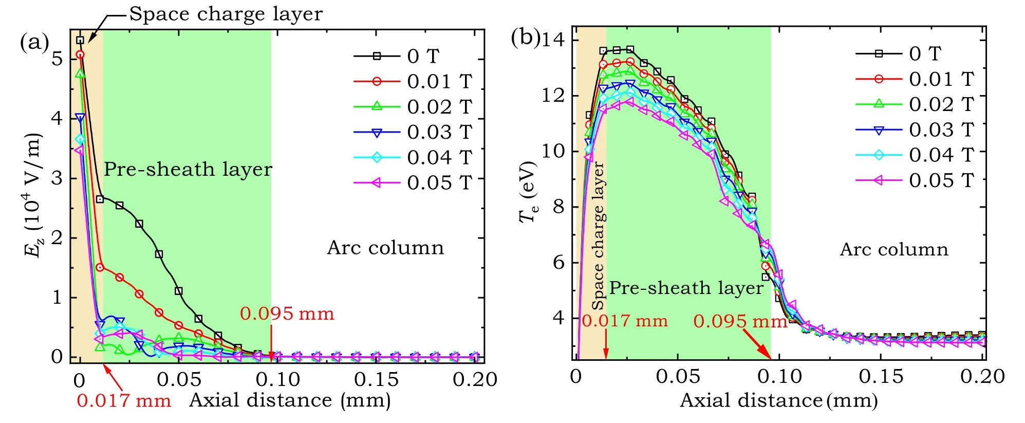
Fig.12.Contact fixed separation 1 mm, arc current 20 kA, and discharge pressure 1 atm.The x-coordinate of 0 mm represents the cathode surface.(a) Electric field intensity distribution under different homogeneous external magnetic fields along the axis at 10000 ns; (b) electron temperature distribution under different homogeneous external magnetic field along the axis at 10000 ns.
5.Conclusions and outlook
In this work, the fluid-chemical model was established based on the drift-diffusion equations of gas dynamics, coupled with the Poisson equation, and considering the complex variations of the collision, recombination,drift, and diffusion of electrons,ions,and excited particles between the electrodes in atmospheric pressure air arc plasma.The validity of the model is verified by comparison with the experiment.The formation processes of an air arc near-cathode sheath with the conditions of atmospheric pressure and high current, and the influence of different currents and different homogeneous external magnetic fields on the formation process of the nearcathode sheath are analyzed.
The radial distribution of electron number density obtained by simulation and experiment[74]shows a Gaussian distribution.The maximum electron number density at the axis and the radial distribution of electron number density obtained by simulation fitted well with the experimental results.This numerical model can predict the behavior of microscopic particles accurately(including electrons and ions)between electrodes and the parameters of the near-cathode sheath during the air arc formation process with atmospheric pressure.
At the initial stage of arc formation, the number density of electrons in the arc column increases at first,then decreases and then increases until it reaches stability, and the number density of positive and negative ions continues to increase until it becomes stable.After arc formation,the number density of electrons, positive, and negative ions are between 1022m−3–1023m−3, and the number density of positive ions near the cathode sheath is 6–8 orders of magnitude higher than that of negative ions.The dominant positive ions between the electrodes are N+2,O+2,O+3and O+4,and the dominant negative ions are O−and O−2.O+2is the most abundant positive ion, and O−is the most abundant negative ion.The thickness of the near-cathode sheath is about 0.095 mm, including the space charge layer it is about 0.017 mm,and the pre-sheath is about 0.078 mm, thus forming a voltage drop in the near-cathode sheath.The current ranges from 20 kA to 80 kA,and the voltage drop in the near-cathode sheath ranges from 11.14 V to 12.45 V.The voltage drop in the near-cathode sheath decreases with the increase of the arc current.
The influence of a homogeneous external magnetic field is also considered in this work and the formation process of near-cathode sheaths with 20 kA arc current under different homogeneous external magnetic fields is analyzed.Under the effect of the homogeneous external magnetic field, the electron number density at the sheath periphery increases, which indicates that the homogeneous external magnetic field makes the arc diffusion but the homogeneous external magnetic field has little effect on the electron number density and electron temperature in the sheath core.The larger the homogeneous external magnetic field is,the smaller the axial electric field intensity in the near-cathode sheath is,and the lower the energy of electrons entering the pre-sheath layer is.This indicates that increasing the homogeneous external magnetic field can weaken the electron impact ionization in the pre-sheath layer.It is shown that, to a certain extent, increasing the homogeneous external magnetic field can reduce the arc energy in the early arc formation process.
Our understanding of development law and basic theories of air arc discharge, the most common type of all discharges, are maturing.However, there is no uniform microscopic method for self-consistent description of arc discharge under all gas pressures.Current and future research should focus on establishing self-consistent numerical models to describe known theories and make accurate predictions.The behavior of particles between electrodes during the air arc sheath formation process with high current is mainly investigated and analyzed in this work.In the following improved model,the heat transfer between the arc plasma and electrode will be taken into account.Using one set of control equations to achieve the coupling of arc-sheath-electrode with atmospheric pressure air arc is the goal of our future research.In addition, in the field of engineering technology, the influence of contact surface morphology, the circuit breaker’s contact materials, and self-generated magnetic field from the arc on preliminary arc behavior can be further investigated by combining the fluid-chemical model established in this work with other existing numerical methods(e.g.,nonlinear surface heating method[84]and MHD method[85]).
Acknowledgments
Project supported by the National Natural Science Foundation of China (Grant No.51977132), Key Special Science and Technology Project of Liaoning Province (Grant No.2020JH1/10100012),and General Program of the Education Department of Liaoning Province(Grant No.LJKZ0126).
猜你喜欢
新航空(2023年11期)2024-01-16 19:13:15
新航空(2023年3期)2023-09-06 05:14:26
作文周刊·小学二年级版(2022年36期)2022-05-30 10:48:04
当代党员(2022年9期)2022-05-20 13:35:21
今日农业(2020年14期)2020-12-14 19:47:34
孩子·小学版(2019年3期)2019-09-10 07:22:44
宝藏(2017年7期)2017-08-09 08:15:16
宝藏(2017年6期)2017-07-20 10:01:01
职工法律天地·上半月(2017年2期)2017-05-17 12:05:09
高中生学习·高三版(2017年2期)2017-03-28 14:16:49

- Chinese Physics B的其它文章
- High responsivity photodetectors based on graphene/WSe2 heterostructure by photogating effect
- Progress and realization platforms of dynamic topological photonics
- Shape and diffusion instabilities of two non-spherical gas bubbles under ultrasonic conditions
- Stacking-dependent exchange bias in two-dimensional ferromagnetic/antiferromagnetic bilayers
- Controllable high Curie temperature through 5d transition metal atom doping in CrI3
- Tunable dispersion relations manipulated by strain in skyrmion-based magnonic crystals