Multifunctional polarization converter based on multilayer reconfigurable metasurface
Ping Wng , Yong Zhng , Yu Wng ,b, Hong-cheng Zhou , Zhong-ming Yn ,b,*
a School of Electrical Engineering, Southwest Jiaotong University, Chengdu, China
b Key Laboratory of Magnetic Suspension Technology and Maglev Vehicle, Ministry of Education, Chengdu, China
Keywords:Multifunctional polarization converter Multilayer metasurface Electrical reconfigurable metasurface Wide operational band
ABSTRACT In the modern wireless communication system, the manipulation for polarization of electromagnetic wave plays a important role in improving the capacity and reliability of communication.In this paper, a multifunctional polarization converter (MFPC) based on the multilayer reconfigurable metasurface is proposed,which can assist the source antenna to transmit and receive multiple polarization signals.The MFPC consists of a grating which can filter out the undesired polarization and four layers of metasurfaces incorporated with PIN diodes.The functions of the MFPC include LTC and LTL polarization conversions,co-polarization transmission and reflection for arbitrary polarization.By changing the states of PIN diodes,the functions of MFPC can be dynamically switched.Loaded on the aperture of source antenna,the proposed MFPC can serve as a transmissive array with multiple polarization channels, and can also provide EM protection for source antenna by reflecting the incoming interference waves.Cascading of the metasurfaces produces Fabry-Perot resonance in the MFPC,and it contributes to the realization of LTC and LTL polarization conversions.To verify the performance of the proposed MFPC, the prototype is fabricated and tested.The measured results show that the fractional bandwidths of four functions are all higher than 31.9% with transmission or reflection coefficients higher than -2 dB.The frequency band of each function is mainly concentrated in S-band.The measured data are in agreement with the simulated results.
1.Introduction
Polarization is one of the fundamental properties of electromagnetic (EM) wave.The manipulation and discrimination of polarization is critical for enhancing the carrying capacity of EM waves to information and the reliability of wireless communication.The polarization modulation was developed to improve the anti-interference capabilities of radars and multiple-input multiple-output (MIMO) systems [1-3].The polarization filtering and diversity were often used to overcome the multipath fading and enhance the signal-to-noise ratio [4,5].Airborne and satelliteborne polarimetric synthetic aperture radars (SAR) were used for observing weather and landform [6].However, the systems with multiple polarization commonly use several polarization channels for transmitters and receivers, which leads to the increase in volume,power consumption and cost.For a compact wireless system,a promising approach is to load a transmission-type polarization converter on the aperture of single-polarization antenna[6,7].The metasurface has provided an excellent candidate scheme for constructing the polarization converter.
As a two-dimensional artificial material composed of periodic units, the metasurface has giant optical activity, low loss, low weight and various of exotic properties,it has been widely used in polarization conversions of EM waves [8,9].Recently, various of polarization converters utilizing metasurfaces were reported.In Refs.[10-12], the linear-to-linear (LTL) polarization converters based on Fabry-perot (F-P) resonant cavity were proposed, they could operate with ultra-wide band and low loss.For linear-tocircular (LTC) polarization conversion, some single layer [13] and multi-layer[14,15]polarization converters were proposed based on anisotropic elements.Although the above-mentioned designs have excellent performances, the fixed functionality of metasurface limits their applications.For achieving switchable functions and enhancing the flexibility, the multifunctional polarization converters (MFPCs) were proposed by integrating RF devices [16-18]or tunable materials[19].However,the addition of tunable devices or materials is always accompanied by the decrease of transmission coefficient and the contraction of operational band, which will deteriorate the radiation efficiency and bandwidth of the feed antenna.
In this paper, a wide-band MFPC based on the multi-layer metasurface is proposed, whose designed schemes include transmission and reflection modes.For the transmission mode, the MFPC can achieve the switchable functions including copolarization transmission, LTC and LTL polarization conversions.For the reflection mode, the incident waves with orthogonal polarization will be reflected by the MFPC, thus it can provide EM protection for source antenna by reflecting the incoming interference waves.The dynamic switches between functions are completed by changing states of the PIN diodes embedded on the metasurfaces.Each layer employed in the MFPC has stable EM responses in a wide frequency band,which is conducive to obtain the large operational bandwidth.Meanwhile, the multiple reflections of waves and F-P resonances excited in metasurface are illustrated in this paper.To verify the design of MFPC, a prototype was fabricated and tested.The measured results shown that the operational bandwidth of the MFPC with each function is more than 31.9%with transmission or reflection coefficients higher than -2 dB.The frequency band of each state is mainly concentrated in S-band.The measured results show agreement with the simulated ones.Comparing with the reported multifunctional transmission-type polarization conversion metasurfaces, the proposed design has more functions, including the manipulations of polarization and propagation mode of EM wave, and has wider operational bands.The proposed design may be applied in satellite communication and polarimetric radars in S-band.
2.Operational principle of the multifunctional polarization converter
The conceptual illustrations of the proposed MFPC with different functions are shown in Fig.1.The top layer of MFPC is a grating composed of substrate and metal strips parallel to x-axis,which only permits y-polarized waves to pass through.The middle layer and bottom layer are reconfigurable metasurfaces integrated with PIN diodes.The states of middle layer can be switched between polarization conversion and co-polarized transmission by changing the bias voltage on diodes.The bottom layer also has two states.At one state,only the x-polarization waves can penetrate the bottom layer and the y-polarization waves will be reflected.At the other state,the waves with arbitrary polarization can penetrate the bottom layer.The functions of the MFPC include LTC and LTL polarization conversions, co-polarization transmission and reflection for arbitrary polarization.The relationships between working states of each layer and the MFPC are shown in Table 1.
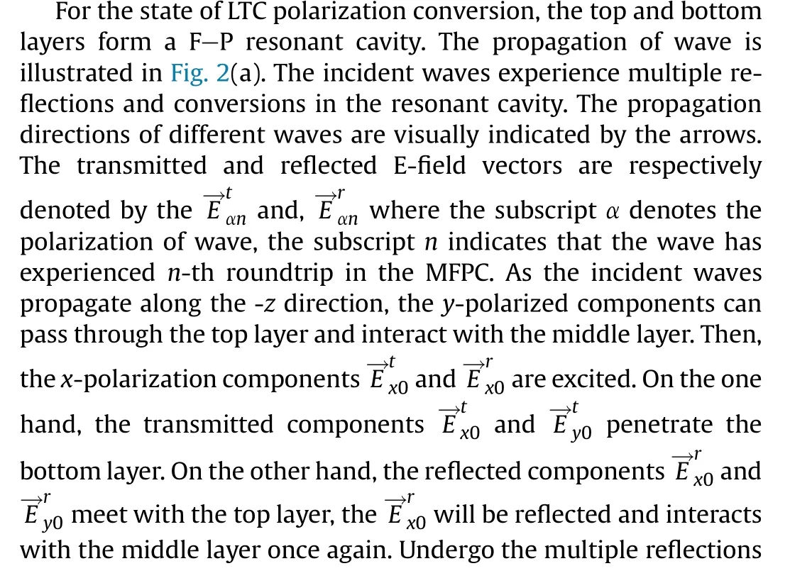

Fig.1.The conceptual illustration of the MFPC with different functions: (a) LTC polarization conversion; (b) LTL polarization conversion; (c) Co-polarization transmission; (d)Reflection for arbitrary polarization.

Table 1Working states of each layer and functions of MFPC.

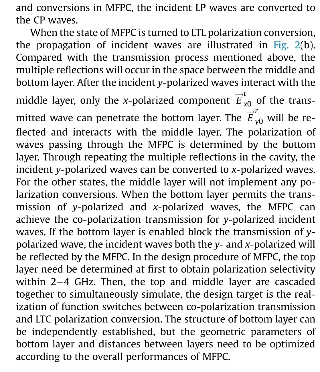
Fig.2.The schematic diagram for the propagation of incident wave: (a) The state of MFPC is LTC polarization conversion; (b) The state of MFPC is LTL polarization conversion.
3.Design and simulations of the multifunctional polarization converter
3.1.Geometric structure of the MFPC
The proposed MFPC consists of five layers,both the middle and bottom layers employ the bi-layer reconfigurable metasurface.The unit cell of MFPC is shown in Fig.3.Each layer of the MFPC is separated by air gap.The period dimension p of the square unit cell is 42.43 mm.The substrates for all layers are FR4 with εr=4.3.The distances between adjacent layers are chosen as follows:h01=19.5 mm,h12=13.4 mm,h23=20.0 mm,h34=21.4 mm.The patterns etched on the middle and bottom layers consist of metal meander lines, they can serve as the elements for polarization conversion and the DC bias lines.Thus, there are no extra feeder lines are introduced for controlling the PIN diodes, which can suppress feeder complexity and the interference [7].
3.2.Design of the top and middle layer
The unit cell of the top and the middle layer are shown in Figs.4(a)-4(d), the simulated results of top layer is given in Fig.4(e).The front side of the top layer is covered by eight metal strips parallel to the x-axis,there are no metal patterns on the back side.The middle layer is composed of two layers of reconfigurable metasurface with identical structures.Although this will lead to a larger profile comparing with the single-layer structure, the bilayer structure can exhibit more stable EM response in wide frequency band,which is conducive to expand the bandwidth of MFPC[14,20].In each substrate of middle layer, the orthogonal copper meander lines which can independently control the transmission coefficients in u- and v-axes are respectively etched on the front and back sides.The Skyworks SMP1345-079LF PIN diodes are embedded in the meander lines on front side.The different equivalent circuits corresponding to the ON/OFF states of the PIN diode are shown in Fig.4(d).The geometrical parameters of the grating and the middle layer are chosen as follows: w1=1.0 mm,w2=1.0 mm, w3= 0.2 mm, d1=4.3 mm.
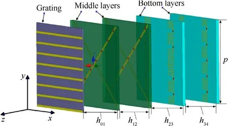
Fig.3.The periodic geometry of the proposed MFPC.
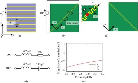
Fig.4.The periodic structures and simulated results of the grating and middle layers:(a)Front view of the grating;(b)Front view of the middle layer;(c)Back view of the middle layer; (d) Equivalent circuits of the PIN diode at ON/OFF state; (e) Transmission coefficients of the grating.
Considering the EM wave interacts with the middle layer, the incident y-polarized wave can be divided into two orthogonal components whose polarization are respectively aligned with uand v-axes.When the PIN diodes in the middle layer are switched on, both the meander lines aligned with u- and v-axes can be equivalent to inductive branches.The transmitted components with u- and v-polarization still can form the y-polarized wave.When the diodes are switched off, the meander line along the vaxis will equivalent to a capacitive branch.Some discrepancies will be produced in the magnitude and phase of transmitted components aligned with u- and v-axes.Therefore, the polarization of transmitted wave synthesized by u- and v-polarized components will be changed.According to our previous work [21], if the transmission and reflection coefficients of a polarization conversion surface (PCS) satisfy the following equation:
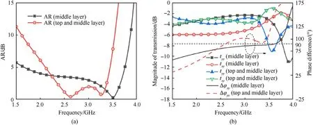
Fig.5.The transmission coefficients and phase difference of the middle layers as PIN diodes are switched off.
the F-P resonant cavity composed of a grating and the PCS can achieve LTC polarization conversion.Where tσρ(rσρ) denotes the transmission(reflection) coefficient of the PCS from ρ-polarized to σ-polarized waves,k0is the free-space wave number.The structure of proposed middle layer has been optimized to reach the condition Eq.(1).The axial ratio (AR) and transmission coefficients of the middle layer and a composite structure which consists of the top and middle layer are shown in Fig.5.The AR of transmitted waves can be obtained as follows:
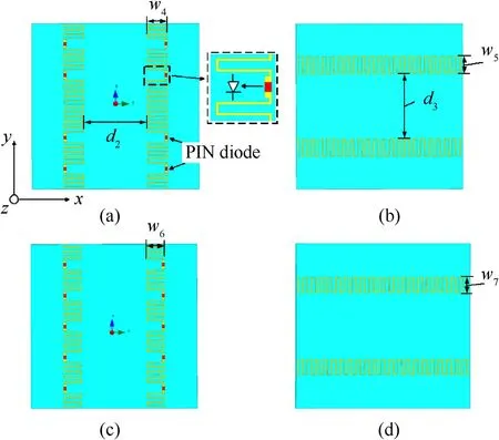
Fig.6.The periodic structure of the bottom layers:(a)Front view of the first metasurface layer;(b)Back view of the first metasurface layer;(c)Front view of the second metasurface layer; (d) Back view of the second metasurface layer.

Fig.7.Equivalent circuits of unit cell of single bottom layer at two polarization: (a) y-polarization; (b) x-polarization.
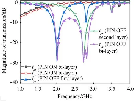
Fig.8.The transmission coefficients of the bottom layers as PIN diodes are switched on/off.
where a=|txy|4+|tyy|4+2|txy|2∙|tyy|2∙cos(2Δφxy),Δφxy=arg(txy)-arg(tyy).The simulation tasks are performed by using CST Microwave Studio.The periodic boundaries are equipped with the unit cell in simulation to obtain the performances of array under plane incident wave.Within 2.22-3.34 GHz,although the Δφxyof composite structure and middle layer are both close to 90°,the|tyy|and|txy|of the composite structure are closer to each other due to the effect of F-P resonance.Therefore, the bandwidth with 3 dB AR of composite structure is larger than the middle layer.
3.3.Design of the bottom layers
The unit cell of the bottom layer is shown in Fig.6, the orthogonal meander lines which are etched on the different sides of the substrate form a polarization selective surface.In the bottom layer, the two metasurfaces are incorporated with 8 and 10 pieces of PIN diodes, respectively.The optimized geometrical parameters of the unit cell are chosen as follows: d2= 16.81 mm,d3= 17.61 mm, w4= 4.4 mm, w5= 4 mm, w6= 3.6 mm,w7=3.3 mm.The equivalent circuits of single surface at x- and ypolarization are shown in Fig.7.Where Tsubdenotes the transmission line substitute for the substrate,L1denotes the inductance generated by the meander lines on front side under y-polarized waves, L2denotes the inductance generated by the meander lines on back side under x-polarized waves.
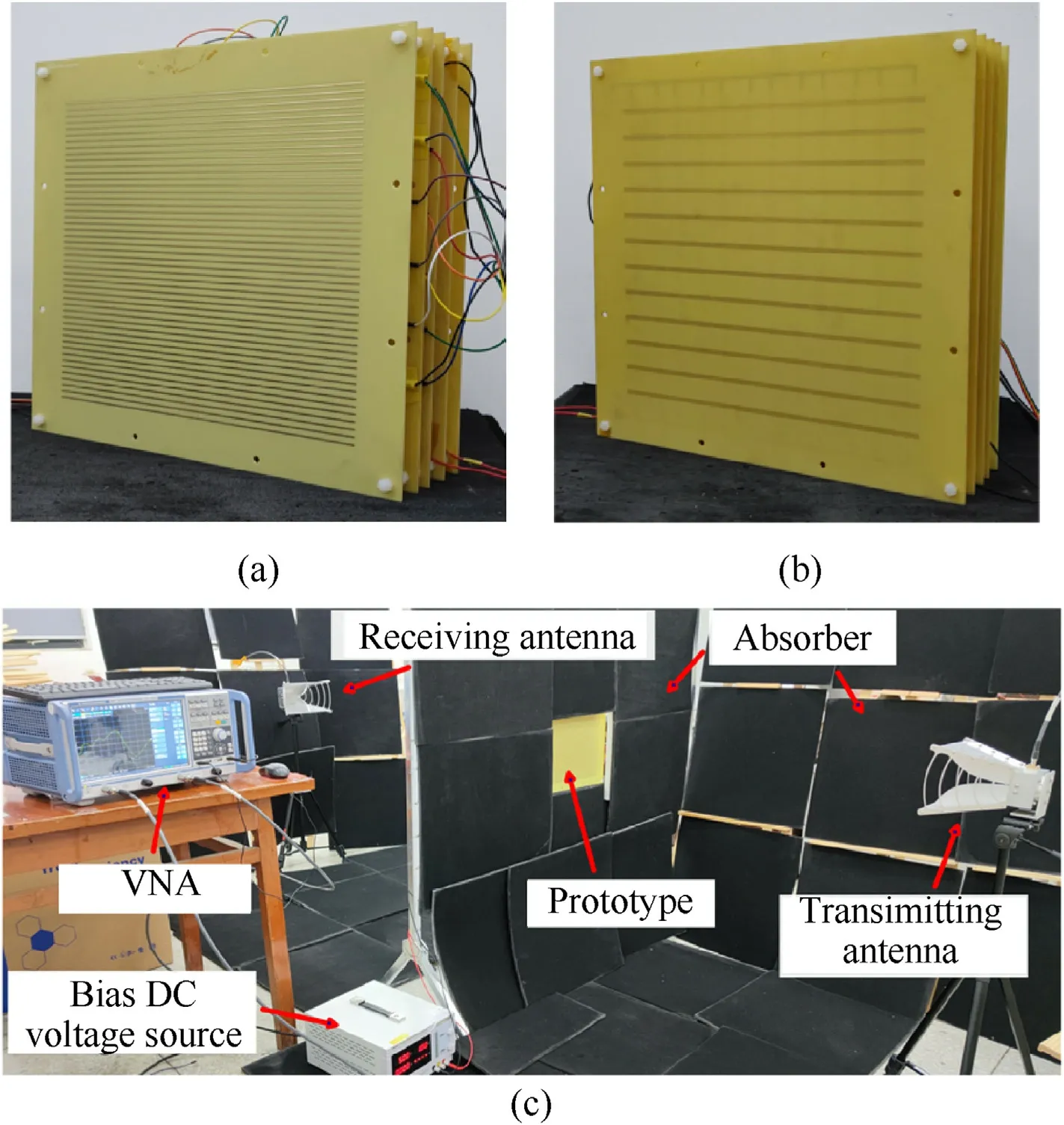
Fig.9.Photograph of the prototype for (a) front view and (b) back view.(c) The schematic scene of measurement setup.
The transmission coefficients of bottom layers are shown in Fig.8.When the PIN diodes are switched off,the series resonance of the CTand L1leads to the stop-band which can hinder the transmission of y-polarized wave.The purpose of placing different numbers of PIN diodes on the first and second surfaces is to introduce different equivalent capacitance, which can cause the stop-band of the two surfaces emerging in different frequencies.A wider stop-band can be created by cascading the two layers.The magnitude of tyyis less than -5 dB within 1.87-3.01 GHz.The meander lines with tortuous structure can exhibit large equivalent inductance, which conduces to improve the transmittance of xpolarization wave.The equivalent inductance will rise with the increase of meander line widths w4-w7[22].When the PIN diodes are switched on, the x- and y-polarization wave can penetrate the bottom layers with similar frequency response.In Fig.8, both tyyand txxare higher than -1.58 dB within 1.87-3.01 GHz.The resistance of PIN diode Rs will cause the transmittance decrease of ypolarization wave.Therefore, the meander lines on the front side are wider than ones on back side to balance the transmittance in xand y-direction.
4.Simulation and experimental verification
To verify the performances of the proposed design under normal incidence plane waves,the prototype was fabricated,and tested by using the free-space method.As shown in Figs.9(a) and 9(b), the prototype with the dimension of 320×320×79.6 mm3consists of 6 × 6 unit cells.Adjacent layers of the prototype are fixed by the nylon screws.The fabrication of metal wires on the prototype utilized the craft of immersion gold.The measurement setup is presented in Fig.9(c), which is mainly composed of two wide-band linear-polarized horn antennas and a vector network analyzer Rohde&Schwarz ZND8.The distance between the transmitting antenna and prototype is 1.5 m,which equals the distance between the receiving antenna and prototype.The distance is larger than 2D2/λu= 1.33 m, i.e., the prototype is placed in the far field of the antennas.Where D is the aperture dimension of horn antenna, λudenotes the free-space wavelength corresponding to 5 GHz,D = 0.2 m, λu= 0.06 m.When the transmission (reflection) coefficients need to be measured, the two horn antennas are placed on different (same) sides of prototype, and the apertures of antennas are always towards the prototype.The working states of PIN diodes on prototype are changed by the bias signals which are provided from the tunable DC voltage source.
The comparison between the simulated and measured results of prototype are shown in Fig.10.Where t+ydenotes the transmission coefficient from y-polarization to right-handed circular polarization, it can be obtained as follows:
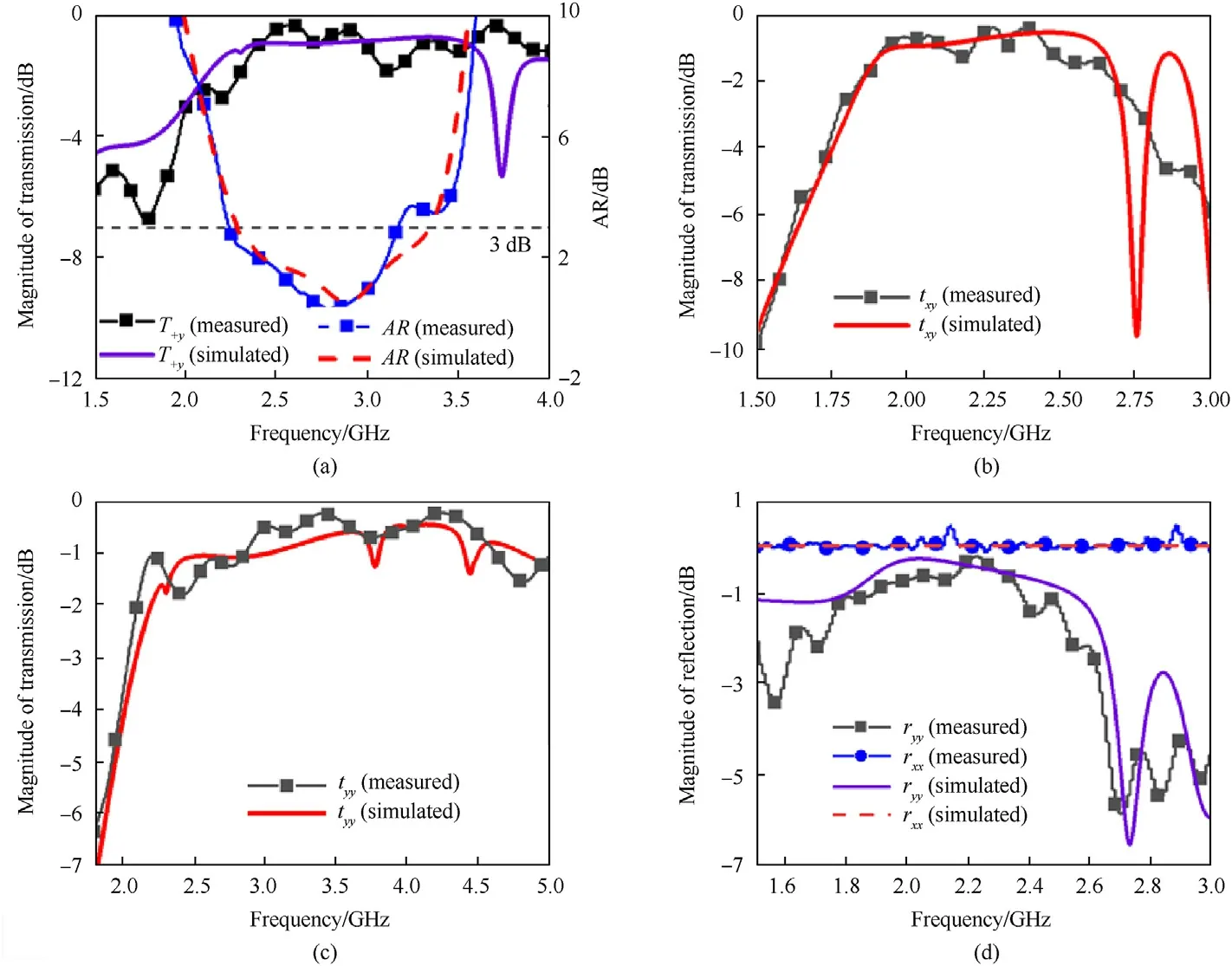
Fig.10.The measured data of prototype comparing the simulated results: (a) LTC polarization conversion; (b) LTL polarization conversion; (c) Co-polarization transmission; (d)Reflection.

Table 2The measured frequency bands of different functions.

Table 3Measured result comparisons of the multifunctional polarization converters.
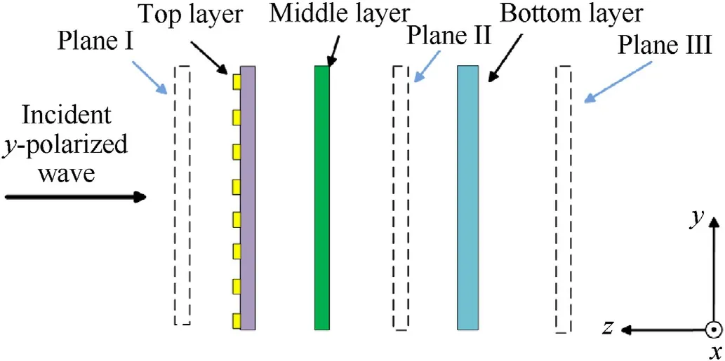
Fig.11.The schematic diagram for exhibiting the positions of three cutting planes and each layer of MFPC.
According to the measured results, the operational frequency band of prototype with transmission or reflection coefficients higher than -2 dB are given in Table 2.It can be found that the bandwidth of each function is larger than 31.9%, the overlapping frequency band is from 2.29 to 2.53 GHz.The measured results are in agreement with the simulated ones.There are some deviations in the measured results which may be caused by the limited fabrication precision and imperfect calibration.In the experiment,the equivalent capacitance and resistance of PIN diode will be changed with the shift of frequency and bias voltage, which will also cause the discrepancy between the simulated and measured results [23,24].Meanwhile, the consistency of diode soldering can affect the measured results [25,26].It can be seen from Fig.10(d)that the magnitude of reflection |ryy| is less than |rxx| within operational band.Because the x-polarized wave can be directly reflected by the top layer,however,the y-polarized wave has to undergo the transmission in MFPC before and after being reflected the bottom layer.The y-polarized wave suffers the extra loss caused by the MFPC.The comparison between the simulated results of proposed design and some other reported transmission-type MFPCs is shown in Table 3.Although the multilayer structure causes the profile of proposed MFPC reaches 0.64λ0(λ0is wavelength corresponding to the center frequency), comparing with the reported designs, the proposed MFPC can exhibit both wider operational band and richer functionalities for manipulating EM waves.Moreover,the complex feed network and high power source are not needed for the MFPC,which is conducive to release the volume and weight of wireless system with multiple polarization (see Table 3).
To illustrate the effect of proposed MFPC on incident wave, we provide the electric field distributions with three planes in x-y cutting view at 2.4 GHz during each state.The positions of three cutting planes and the electric field distributions are shown in Figs.11 and 12, where φ denotes the phase of incident wave.The incident y-polarized wave propagates along the-z axis.In the plane I, the electric vectors are always parallel to y-axis.For the state of LTC polarization conversion, the incident wave experiences multireflection and polarization conversions under the action of F-P resonances, the electric vectors rotate clockwise in the plane II.The incident LP wave is converted to the CP wave.The electric field in plane III remains circularly polarized and has a phase delay relative to plane II.For the state of LTL polarization conversion, as shown in the plane II,the electric vectors of the incident wave are twisted after passing through the middle layer.In plane III, the directions of electric vectors are locked to the x-axis.For the state of co-polarization transmission, the directions of the electric vectors in plane III are preserved on the y-axis.For the state of reflection,the magnitude of electric field in plane III is low, the MFPC can effectively suppress the transmission of incoming wave.
5.Conclusions
To expand the polarization channels of the compact wireless communication system,a MFPC based on multilayer metasurface is proposed in this paper.The MFPC consists of a single-layer grating and four layers of reconfigurable surfaces.By switching the working states of PIN diodes embedded on the MFPC, the functions can be changed between LTC and LTL polarization conversions, copolarization transmission and reflection for incident waves.Therefore,the MFPC can serve as a transmissive array with multiple polarization channels and a radome for EM protection.Meanwhile,the MFPC exhibits wide operational band and high transmission or reflection coefficients.The prototype test verifies that the proposed MFPC has reliable capability for manipulating the EM wave, the measured results of the MFPC are consistent with the simulated ones.Compared with the reported transmission-type polarization converters,the proposed design has advantages of versatility,wide band and low loss.The design of MFPC may provide an approach for manipulating multiple polarization and achieving transmissionreflection switching, it has application prospects in S-band radar and satellite communication.
Declaration of competing interest
The authors declare that they have no known competing financial interests or personal relationships that could have appeared to influence the work reported in this paper.
Acknowledgements
This work was supported in part by the Joint Funds of the National Natural Science Foundation of China (G02) (Grant No.U1834203) and in part by of the Science and Technology Department of Sichuan Province (S01) (Grant No.2020JDTD0009).
- Defence Technology的其它文章
- Eigen value analysis of composite hollow shafts using modified EMBT formulation considering the shear deformation along the thickness direction
- Synthesis of energetic coordination polymers based on 4-nitropyrazole by solid-melt crystallization in non-ionization condition
- RDX crystals with high sphericity prepared by resonance acoustic mixing assisted solvent etching technology
- Study of residual stresses and distortions from the Ti6Al4V based thinwalled geometries built using LPBF process
- Modeling and simulation of solvent behavior and temperature distribution within long stick propellants with large web thickness undergoing drying
- Assessment of the ballistic response of honeycomb sandwich structures subjected to offset and normal impact

