
Modeling of Micropores Drilling Force for Printed Circuit Board Micro-holes Based on Energy Method
2023-10-29 11:41ZHENGXiaohu郑小虎RUANHaoCHENHongbo陈宏博LIUXiaojia刘骁佳LIUZhenghao刘正好
ZHENG Xiaohu(郑小虎), RUAN Hao(阮 浩), CHEN Hongbo(陈宏博), LIU Xiaojia(刘骁佳), LIU Zhenghao(刘正好)
1 Institute of Artificial Intelligence, Donghua University, Shanghai 201620, China 2 Shanghai Industrial Big Data and Intelligent Systems Engineering Technology Center, Shanghai 201620, China 3 College of Mechanical Engineering, Donghua University, Shanghai 201620, China 4 Shanghai Institute of Aerospace Precision Machinery, Shanghai 201600, China
Abstract:The quality of printed circuit board (PCB) micro-hole processing directly determines the stability of the inner and outer circuit connections. Micro-hole drilling technology is a typical method for PCB micro-hole processing. The problem of optimal control of its drilling force is one of the main factors affecting the quality of micro-hole machining. To address this problem, the thrust forces and torques in PCB drilling were first modeled and analyzed, and the corresponding prediction models were established. The drilling force analysis was carried out through the micro-hole drilling experiment, the specific cutting energy under different feed rates was calculated, the influence of the size effect was clarified, and the accuracy of the prediction model was verified. The result shows that during the drilling of glass fiber cloth, changes in the material removal mechanism are induced as the feed per revolution is varied. When the feed per revolution is less than the tool edge radius, the glass fiber is not cut by the main cutting edge, but is crushed and broken. When the feed per revolution is greater than the radius of the tool edge, the glass fiber is cut by the main cutting edge. At the same time, the established analytical model can accurately reflect the influence of the size effect on the drilling torque in PCB micro-hole drilling, and the error is within 10%. This method has certain practical application value in controlling PCB micro hole processing quality.
Key words:printed circuit board(PCB); micro-hole drilling; predictive model; size effect; multi-layer material
0 Introduction
With the increasing demand for data transmission in the information age, it has brought great challenges to the development of printed circuit board (PCB) technology that undertakes data transmission carriers. As an important micro-component for the connection and support of components in electronic products, it is widely used in micro-electromechanical systems (MEMS), electronics and biomedicine industries[1-3]. The micropores inside the PCB are the main form of information exchange between layers of the multi-layer PCB, so it is particularly important to ensure the micropores processing of composite materials represented by the glass fiber reinforced polymer (GFRP)[4-5]. Due to its high efficiency and high precision, micro-hole drilling technology is the main method for micro-diameter processing. As for the research on PCB drilling, domestic and foreign scholars usually focus on the optimization of the drilling path, the control of the drilling temperature, and the optimal design in the selection of drilling materials[6-9]. With the development trend of miniaturization, integration and precision of electronic products, the number of micropores, the diameter of micropores and the quality of the wall of the PCB have put forward new requirements[10]. Therefore, drilling force modeling is important for predicting the quality of PCB micro-hole machining and improving tool life.
A lot of research has been done in China and abroad on the modeling of drilling forces for multi-layer composite materials. Diaz-Alvarezetal.[11]proposed a relevant model for the drilling of biocomposite materials, and analyzed the influence of different conditions on the drilling quality during drilling. Lietal.[12]developed a drilling force model based on oblique cutting theory, which could be used to predict the thrust force and torque of deep hole drilling with staggered teeth boring and trepanning association (BTA). Anandetal.[13]used the method of converting right-angle cutting into the oblique-angle cutting to predict the mechanical model of thrust force and torque of micro-drilling of carbon fiber reinforced plastic composite laminates. In order to control the layering and burr height of laminated materials, relevant scholars[14-15]have proposed different mechanism models to predict the drilling force and torque suffered by carbon fiber reinforced plastics (CFRP)/Ti machining. Gaikheetal.[16]predicted the thrust force and torque for drilling glass fiber reinforced plastic materials to investigate the effect of different combinations of cutting speed and feed rate on thrust force and torque. Many studies have shown that in the field of micro-hole drilling, research on drilling force and its characteristics is crucial for controlling the quality of micro-hole processing. However, the application of the drilling force model to PCB micro-drilling is seldom studied and needs to be further explored.
For the modeling issue of PCB micro-hole drilling, this paper established an analytical model of PCB micro-hole drilling force based on a specific cutting energy formula, aiming to predict thrust force and torque. Then, micro-hole drilling experiments were conducted to analyze drilling force while clarifying the influence of size effects during the drilling process. Finally, the experimental data were used to verify the analytical model and provide guidance for quality control of micro-hole drilling.
1 Establishment of PCB Micro-hole Drilling Force Model
In this study, the analytical model method is used to model the thrust force and torque in PCB drilling, as shown in Eqs. (1) and (2). Shawetal.[17]established a drilling force prediction formula for metal processing, including the axial force and torque prediction formula. The specific form is as follows:
(1)
(2)
whereFis the thrust force,Tis the torque,HBis the hardness of the workpiece,cis the chisel edge length,dis the diameter of a drill, andfis the feed rate. The other parameters,a,K′1,K′2,K′3,K′4andK′5, can be obtained by drilling experiments. In the above formula, in addition to the existence of 6 fixed constants, the ratioc/dof the chisel edge to the drill diameter is also a constant, so the above formula can be simplified as
F=K1(fd)1-a+K2d2,
(3)
T=K3f1-ad2-a,
(4)
whereK1,K2andK3are new constants.
Shawetal.[17]established another equation of calculating torque based on size effect theory, which was the relation between effective specific cutting energyuand (fd)-a, shown as
(5)
Dharan pointed out in his study[18]that since the above equations are discussed mainly for the work done by the tool, related to material properties and machining parameters, avoiding the issue of tool geometry. Therefore, Eqs. (1) and (2) with suitable values ofa,K′1,K′2andK′3can be used to predict the drilling force in composites as well, in addition to metal drilling.
Since the prediction model can be determined after the values ofa,K1,K2andK3are obtained, the logarithm of both sides of Eq. (5) can be taken at the same time, as shown in Eq. (6), where the constantais still obtained through Eq. (5). The torqueTis measured experimentally.
(6)
When the specific cutting energyuis calculated, Eq. (6) can be regarded as a linear equation with lg (fd) as the independent variable. The regression equation of lguand lg (fd) can be obtained through experiments, and the coefficient of the regression equation is (-a), which is the slope of the straight line.
After the indexais determined, then (fd)1-aandf1-ad2-ain Eq. (3) and Eq. (4) are taken as two variables, and the logarithms are taken for each of the two equations, and Eqs. (3) and (4) are converted into 2 linear equations with (fd)1-aandf1-ad2-aas independent variables respectively. In order to determine the value of the above constants, it is necessary to carry out micro-hole drilling experiments. The regression equations ofF,Tand (fd)1-a,f1-ad2-aobtained through the experiments are the equations ofFandT.
2 PCB Micro-hole Drilling Experiment
2.1 Experimental procedure
Since the size effect in PCB micro-drilling process is mainly reflected in the change of drilling specific energy, which is mainly obtained by drilling torque calculation, this study adopts the experimental method of dynamometer torque measurement to analyze the size effect in PCB micro-hole drilling process and provides experimental data for drilling force model.
In this study, the drilling force measurement experimental platform designed with reference to the relevant micromachining literature[19-20]is shown in Fig.1. In Fig.1,Xrepresents the left-right movement,Yrepresents the front-back movement, andZrepresents the up-down movement. The platform uses a Kistler9272 dynamometer (originally from Winterthur, Zurich state, Switzerland) to measure torque and conduct micro-hole drilling experiments with a diameter of 0.4 mm. The geometric parameters of the drill are shown in Table 1. And the processing material is FR-4 double-sided copper-clad PCB, and its performance parameters are shown in Table 2.
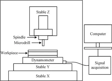
Fig.1 Schematic of hardware system for force measurement

Table 1 Characteristic parameters of FR-4 board

Table 2 Geometric parameters of drill bit
In this study, the single-factor experimental method is used to study the influence of the size effect during PCB drilling by analyzing the torque variation with different feed per revolution selected while the spindle speed is kept constant. The torque signals obtained are shown in Fig.2.

Fig.2 The measured torque signals(feed=0.002 mm/r, speed=40 000 r/min)
Some of the experimental parameters are shown in Table 3. The experiments are repeated three times for each group.

Table 3 Experimental parameters
2.2 Determination of model constants
The drilling force model constant was determined by micro-hole drilling experiments, and the fitted curve between the specific cutting energy lguand lg(fd) is obtained after data analysis, as shown in Fig.3. The fitted equation is shown as
lgu=2.065-0.418 9lg (fd).
(7)
The slope of Eq. (7) is the value of (-a), then we can getaas 0.418 9.

Fig.3 lg u vs lg(fd) (d=0.4 mm)
Therefore, after substituting the value of the constanta, the fitting curve between the thrust force and (fd)1-ais determined, as shown in Fig.4, and the determined fitting equation is the thrust force model shown as
F=1.201+341.4(fd)0.5811.
(8)
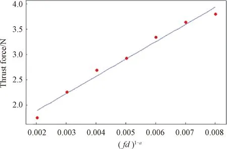
Fig.4 Thrust force vs (fd)1-a (d=0.4 mm)
Similarly, the fitting curve between the obtained torqueTandf1-ad2-ais shown in Fig.5, and the torque fitting equation is shown as
T=-0.0089+14.79f1-ad2-a=
-0.0089+14.79f0.5811d1.5811.
(9)
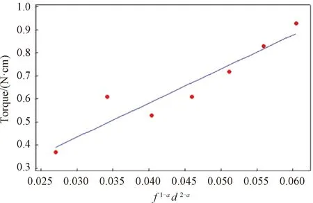
Fig.5 Torque vs f1-ad2-a (d=0.4 mm)
3 Results and Discussion
3.1 Analysis of experimental results
After the above experiments, the variation curve of the relationship between torque and feed per revolution can be obtained, as shown in Fig.6. Figure 6 reflects that the relationship between drilling torque and feed per revolution is generally proportional. In particular, there is a small jump in drilling torque when the feed is 0.003 mm/r, but a significant drop in drilling torque when the feed is 0.004 mm/r, followed by a continuous positive increase, a phenomenon that occurs due to the effect of size effect in micro-fabrication.

Fig.6 Feed per revolution vs torque (d=0.4 mm, speed=40 000 r/min)
The relationship between specific cutting energy and feed per revolution is shown in Fig.7, where the value of specific cutting energy is derived from Eq.(5), which reflects the general trend of decreasing specific cutting energy as feed per revolution increases. Among them, the specific cutting energy can jump significantly when the feed is 0.003 mm/r, indicating that the material removal process is mainly based on extrusion at this stage. When the feed reaches 0.005 mm/r, the change of specific cutting energy tends to be stable, indicating that in the steady-state cutting stage, the fiber material mainly occurs shear fracture.
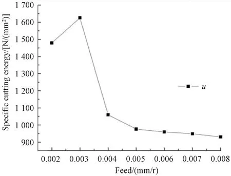
Fig.7 Specific cutting energy vs feed (d=0.4 mm, speed=40 000 r/min)
The structure of glass fiber cloth is shown in Fig.8. Glass fiber cloth is made of glass balls or glass blocks, which are melted, drawn and spun at high temperatures. Each bundle of the original filaments is composed of hundreds or even thousands of monofilaments. Due to the characteristics of high tensile strength and high brittleness of glass fiber, in the process of drilling glass fiber cloth, with the change of the feed per revolution, the material removal mechanism will change. The diameter of the glass fiber in the PCB board used in this study is 0.011 mm, which is exactly within the variation range of the tool edge radius.

Fig.8 Picture of structure of glass fiber cloth
The principle of the size effect of PCB micro-drilling is shown in Fig.9. When the feed per revolutionfrevis greater than the radius of the tool edger, the glass fiber is cut by the main cutting edge; whenfrevis less thanr, the glass fibers are crushed after being squeezed, and the above changes in the material removal mechanism are specifically reflected as changes in specific cutting energy.

Fig.9 Size effect in micro-drilling of PCB
3.2 Model verification
After obtaining the fitting equations for the thrust force and the torque, those are Eqs. (8) and (9), experimental verification was conducted using drill bits with diameters of 0.6 mm and 1.0 mm, and the verification results are shown in Figs.10 and 11. The analysis shows that the predicted drilling force of 1.0 mm diameter drill bit is more accurate than that of 0.6 mm diameter, while the results obtained from the experiment and the theoretical calculation show the same variation trend with an error within 10%, so the analytical model is reasonably designed and the results are valid.

Fig.10 A plot showing comparison of experimental values and estimated values of the thrust force (speed=40 000 r/min)

Fig.11 A plot showing comparison of experimental values and estimated values of the torque (speed=40 000 r/min)
4 Conclusions
1) Based on Shaw and Oxford established cutting equation theory[17], the constantsa,K′1,K′2,K′3,K′4,K′5andc/dcombination formulas determined by experiments are simplified. After simplification,K1,K2andK3are obtained as new constants, and the drilling force model constants are determined through the drilling force measurement experimental platform, which provides experimental data for the specific cutting energy, thrust force and torque fitting curves.
2) During the drilling of glass fiber cloth, changes in the material removal mechanism are induced as the feed per revolution is varied. When the feed per revolutionfrevis less than the tool edge radiusr, the glass fiber is not cut by the main cutting edge, but is crushed and broken. When the feed per revolutionfrevis greater than the radiusrof the tool edge, the glass fiber is cut by the main cutting edge.
3) The fitted formulas for thrust force and torque are obtained experimentally and verified by data comparison. Experiments are conducted using drill bits with diameters of 1.0 mm and 0.6 mm, respectively, and the error rate of the prediction model is found to be within 10%, indicating that the method has some practical application.
This study focuses on the optimization control of drilling force in PCB micro-hole machining, and establishes a prediction model for drilling force. At the same time, drilling force analysis and model validation are conducted through micro-hole drilling experiments. Through comparison of experimental data, it is found that the prediction error rate of the model is within 10%, indicating that the prediction method has certain practical application functions.
In addition, for PCB board micro-hole drilling, the drilling quality can be further improved by the following ways. One is to optimize the tool structure and improve the working accuracy of the machining platform. The other is that we can continue to establish the formula for calculating the edge stress of micro milling cutter and establish the edge design method of micro milling cutter based on this to optimize the PCB micro hole drilling process. These will be the next major research directions.
 Journal of Donghua University(English Edition)2023年5期
- Journal of Donghua University(English Edition)的其它文章
- Preparation of Cellulose Acetate Butyrate Porous Micro/Nanofibrous Membranes and Their Properties
- Highly Sensitive Electrochemical Detection of Nitrite Based on Cationic Surfactant Modification of Conductive Carbon Black
- Concise Synthesis and Fertility-Promoting Activity of Thiamidol
- Calculation and Analysis of Acoustic Characteristics of Straight-Through Perforated Pipe Muffler Based on Multilayer Sound Absorbing Material
- Design and Structure Optimization of Plenum Chamber with Airfoil Baffle to Improve Its Outlet Velocity Uniformity in Heat Setting Machines
- Image Retrieval Based on Vision Transformer and Masked Learning