Research on Frequency Improvement for LOX/kerosene Rocket Engine-Servo Loop
WANG Ke,HE Jiang,LI Miaoting,NIE Jiawei
Xi’an Aerospace Propulsion Institute,Xi’an 710100
Abstract: In order to suppress the low-frequency resonance phenomenon in the engine-servo loop during the development of the 1200 kN LOX/kerosene engine,the inherent characteristics of the loop were analyzed by finite element simulation and experiment.Based on the method of finite element simulation,the modal analysis of the engine-servo loop was carried out,and the finite element model was modified according to the results of modal test,so that the results of finite element simulation were in agreement with the results of the modal test.On this basis,various sensitive factors were analyzed with the finite element software.The results show that the stiffness of the bearing and gimbal mount as well as the stiffness and dip angle of the pull rod have great influence on the natural frequency of the engine.Based on these conclusions,the structure of the engine was improved.The modal analysis of the improved single-engine and double-engine structures was carried out using numerical simulation and modal test.The results show that the low-order frequency of the improved single-engine and double-engine structures was significantly improved,and the effectiveness of the improved scheme was verified,which provides a solution to improve the low-order natural frequency in the engine-servo loop.
Key words: LOX/kerosene engine,engine-servo loop,low-order frequency characteristics,modal analysis
1 INTRODUCTION
The load frequency of the engine-servo loop has an important effect on the amplitude and phase characteristics of the servomechanism,which affects the stability quality of the rocket control system[1].The inertia load torque produced by the engine following the vehicle’s motion not only causes engine swing angle bias,but also causes the coupling between the vehicle’s elastic vibration frequency and the local frequency characteristics of the engine-servo loop because it contains the vehicle’s elastic vibration signal.There is a coupled resonance boundary between the local dynamic characteristics of the engine-servo loop and the vehicle’s dynamic characteristics.For a system whose vehicle’s structure and dynamic characteristics are determined,it is necessary to ensure that the load frequency of the engine-servo loop is higher than the coupled resonance boundary to avoid local and global resonances.
In the early stage of the development of the 1200 kN liquid LOX/kerosene engine,the low-frequency resonance phenomenon occurred many times during the joint test of the engine and servomechanism,where the engine and test stand shook violently,which was also seen in the measured strain,vibration and displacement data of the engine.It is found that the resonance occurs at resonant frequency of near 6 Hz.The analysis show that the first-order frequency of the engine-servo loop is about 6 Hz,which is lower than the minimum frequency required by the rocket.
There are some changes in the natural frequency of the carrier rocket during the whole course of flight.The transverse natural frequency of the rocket ranges between 2 Hz and 3 Hz,and the longitudinal natural frequency ranges from 4.5 Hz to 9 Hz.Hence,if the engine has a resonant frequency of about 6 Hz,the low frequency resonance occurs when the rocket adjusts its attitude through the engine,and an excitation of about 6 Hz will be applied to the rocket.This may damage engine components,cause engine failure,damage the swing system,and affect the flight control accuracy of the vehicle,resulting in failure to complete the predetermined attitude adjustment.It also can initiate concurrent POGO problems[2]and cause rocket low-frequency resonance.In this case,it may lead to damage to the equipment and injury to passengers on-board the rocket,and even cause the rocket fly out of control or the launch vehicle structure to fail,thus leading to destruction of the vehicle and loss of lives[3].Therefore,the low-frequency resonance of the engine at about 6 Hz was the first problem to be solved before the full engineering application of the engine could be realized.
For the low frequency characteristics of liquid rockets,HUANG[4]used the finite element method to calculate the modal of four parallel connected liquid rocket engines.The engine model was simplified in the research,which not only reflects the main characteristics of the structure,but also saves computer resources and time.The natural frequency and modals of four parallel connected engines could be obtained.Many of these modals have large axis motion,therefore it is necessary to avoid them coupling with the low frequency pulsation of the engine and the low-frequency vibration of the vehicle.LI[5]developed a linear small perturbation dynamics transfer matrix model for analysis of a LOX/kerosene staged combustion cycle engine,which was based on the modeling technology of modularization and topology generation.As per the alternating current fluid network theory,the low frequency characteristics of the engine system were investigated by using the transfer function method.HE[6]established a linearized small deviation frequency domain model by emphatically considering the influence of gas turbine and pump dynamic characteristics,which was based on the liquid oxygen system in a LOX/kerosene staged combustion cycle engine.The influence of the gas turbine pressure ratio,the dynamic gain of the oxygen pre-pressurized pump and the gas mixing section on the system frequency characteristics were calculated by using a complex coefficient state space matrix.The results showed that under the low pressure ratio condition of the preloaded turbine,the system response amplitude becomes larger,which has less influence on the system frequency.The higher the dynamic gain of the pressurized pump,the lower the system frequency and the larger the amplitude.The longer the gas mixing section,the lower the system frequency and the smaller the amplitude.Based on the Rayleigh-Plesset equation and the characteristics of gas jet,the transfer function model of the gas condensing process in the pipeline between pumps was established in conjunction with the oxygen pipeline,pump and other component models[7].The simulation results showed that high inlet pressure and super-cooled liquid oxygen change the inertia and flexibility of jet gas and increase the characteristic frequency of the oxygen system.The results of the engine thermal test under different boundary conditions showed that increasing the inlet pressure of oxygen circuit or decreasing the temperature of liquid oxygen can increase the frequency of the oxygen system from 8.3 Hz to 11 Hz,which is consistent with numerical simulation results.WANG[8]used the transfer matrix method to simulate and analyze the frequency characteristics of a large thrust LOX/LH2 rocket engine system.It is found that the mid-and high-frequency oscillation characteristics of the gas generator cycle engine system are obvious,but the low-frequency oscillation characteristics are not obvious.Therefore,it can be concluded that the high-thrust LOX/LH2 engine with gas generator cycle has little effect on the low-frequency longitudinal coupling vibration of the large launch vehicle.From the above research,we can see that low-frequency vibrations are common problems in liquid rocket engines.Researchers often use numerical simulations to analyze various influencing factors of low-frequency vibrations,so as to establish the main factors that affect the low-frequency vibrations,and then provide guidance for the design of an engine and rocket’s overall structure.
After analyzing and studying the data,it was decided to take the combination of modal test and simulation analysis to determine the inherent characteristics of the engine.The simulation model was used to analyze various sensitive factors,to determine the improvement direction for the engine,and then to implement structurally,conduct test and verification,thus to ensure the inherent characteristics of the engine meet the overall requirements.
2 ENGINE STRUCTURE SPECIFICATIONS
The 1200 kN liquid LOX/kerosene engine is a pump-pressure combustion cycle engine,and its structure is shown in Figure 1.The pre-pump swing mode was adopted in order to realize the thrust vector control of the engine.The main components include a thrust chamber,a gas generator,a turbine pump,valves,a gimbal mount,and frames.The servomechanism or pull rod is hinged with the frame and the thrust chamber,and the frame is connected with the gimbal mount by bolts.The gimbal mount and the thrust chamber are hinged by two rigid shafts arranged on the thrust chamber,and bearings are arranged in the middle to realize the relative rotation of the thrust chamber and the gimbal mount.
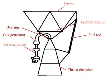
Figure 1 Diagram of engine structure
3 ANALYSIS OF LOW FREQUENCY CHARACTERISTICS AND PRINCIPLE OF MODAL TESTS
3.1 Low Frequency Characteristics Analysis Method
Targeting the low-frequency resonance phenomenon in the engine during testing,the inherent characteristics of the engine were studied by means of a combination of test and simulation analysis.The main analysis approach for the low frequency characteristics of the engine are as follows:
1) The modal tests of the engine and the servomechanism were carried out to determine the vibration mode of the engine,which provides the basis for the preliminary establishment of the simulation model.
2) A finite element model was established to analyze the engine modal,and the simulation setting was adjusted in line with the modal test results,so that the simulation results would be consistent with the test results.
3) The influence factors of low frequency were analyzed by using finite element software,and engine structure was upgraded according to the analysis results.
4) The simulation analysis and modal test of the improved engine and servomechanism were carried out to verify the improved results.
3.2 Modal Test Principle
Modal test analysis is divided into four stages[9,10]: test excitation,signal analysis,parameter identification and application of modal parameters.The modal parameters of the structure can be identified by determining the frequency response function.That is,by measuring the excitation forcef(t) and the response outputx(t) of the system under random excitation or percussion excitation,the frequency response function of the system can be determined according to the definition:

whereH(ω) refers to the frequency response function,Gxf(ω)refers to mutual power spectrum of force and response,Gff(ω)refers to self-power spectrum of force excitation.
For a multi-degree-of-freedom system with viscous damping,the dynamic differential equations are as follows:

Through Laplace transform,we can obtain:
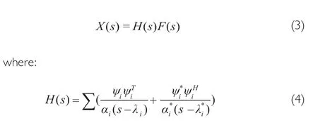
Whens=jω,the frequency response function of the system can be expressed as follows:

whereλ i=αi+αi=-ξiωni,ξirefers to the modal damping ratio,ωnirefers to the natural frequency,ψirefers to the vibration mode.
The corresponding function of the pulse can be obtained by inverse Fourier transform of the Equation (5):
The measured frequency response function obtained from the Equation (1) and the theoretical frequency response function obtained from the Equation (5) can be used to determine the natural frequency,damping ratio and vibration mode of the structure.The modal parameters of the structure can be identified from the time domain by the pulse response function as Equation (6),along with the natural frequency,damping ratio and vibration mode of the structure.
4 SIMULATION ANALYSIS AND EXPERIMENTAL STUDY
In the aspect of liquid rocket engine dynamic modeling,YANG[11]established the launch vehicle’s dynamic model for engine-servo loop,and analyzed the influence of load frequency on the amplitude-phase characteristics of the servomechanism and the stability of vehicle.DONG[12]analyzed the vibration characteristics of the engine by modal test and commercial software.The simulation results were in good agreement with the test results.YUAN[13]studied the low frequency structure dynamics of liquid rocket engine,and established a credible low frequency dynamic model of the engine.The above research shows that it is feasible to analyze the low frequency characteristics of engines by finite element simulations,which provides some guidance for the low frequency finite element analysis and modal test of engine-servo loop.
4.1 Establishment of Simulation Analysis Model
In this study,the finite element dynamic model of the engine-servo system was established by using the finite element software.Based on the modal test results,the finite element parameters were modified,so the final model could reflect the low frequency characteristics of the system correctly.Thus,the influence of each factor on the dynamic characteristics of the system could be analyzed,which provided a basis for the subsequent structural improvement.
The engine finite element model,as shown in Figure 2,is composed of the engine swing part,a gimbal mount,frames,the pull rod and upper and lower support models.
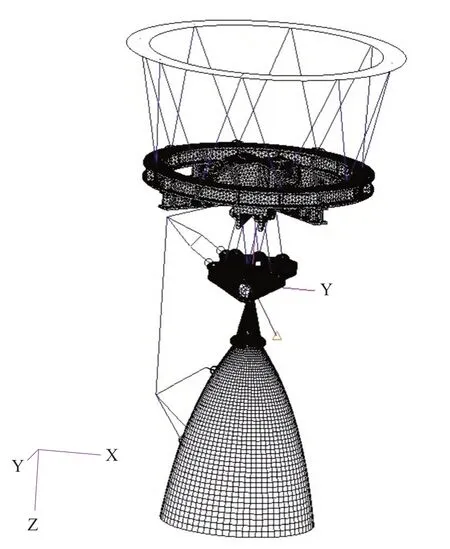
Figure 2 Engine finite element model
In the test condition,the top of the frame is connected with the moving frame and the static frame.Due to the stiffness of the moving frame,the influence of the moving frame can be neglected based on the static frame which is large enough.
After continuous improvement,the first three modals obtained by finite element simulation were in good agreement with the modal test results.Table 1 and Table 2 show the simulation calculation and modal test results of pull rod state and the servomechanism zero-position maintenance state,respectively.

Table 1 Simulation calculation and modal test results of pull rod state
It can be seen that the first three order simulation calculation results of the engine were in good agreement with the modal test results,and the established model reflects the low frequency characteristics of the system,which shows that the structural sensitivity analysis based on the model is feasible.
4.2 Sensitive Factor Analysis and Test Verification
In order to better analyze the low frequency characteristics of the engine,the influence of the parameters on the low frequency modal of the engine was analyzed based on the simulation model.The influence factors of low frequency include the center of mass and mass of the engine,the radial stiffness of bearings,the stiffness of frames,the stiffness of gimbal mount,the stiffness and the inclination angle of pull rod.The effectsof the above factors on low frequency are shown in Figure 3.Where the mode corresponding to the first-order frequency is in the direction of vertical swing,and the mode corresponding to the second order frequency is in the direction of oscillation.

Figure 3 Engine low frequency sensitivity analysis diagram
From the Figure 3,we can see that:
1) The stiffness of bearings and gimbal mount has great influence on the low frequency modal of engine.Since it is difficult to improve the stiffness of the original gimbal mount structure,it was necessary to redesign a new gimbal mount scheme.
2) The influence of the stiffness of the pull rod on the low frequency modal along the swing direction cannot be neglected.The frequency along the swing direction can be increased by increasing the stiffness of the pull rod,but the effect becomes smaller when the stiffness is above a specific value.
3) The frequency along the swing direction can be increased by improving the angle of the pull rod,but the diameter of the rocket and the limitation of the installation space should be taken into account.
5 STRUCTURE IMPROVEMENT AND VERIFICATION
5.1 Structure Improvement
Through the analysis of the stiffness and low frequency simulation of various frames and gimbal mount design schemes,four main measures to solve the low frequency problem were determined:
1) Increase the stiffness of frames and gimbal mount;
2) Increase the angle of servomechanism;
3) Increase the stiffness of the gimbal mount along the swing direction;
4) Improve the stiffness of the servomechanism and its lower fulcrum loop.
5.2 Engine Dynamic Characteristics Prediction
The finite element software was used to simulate the improved single-engine and double-engine structures.The finite element model is shown in Figure 4.The results of the engine simulation are shown in Table 3.It can be seen that the first-order frequency of the single-engine and double-engine engines can be improved obviously via servomechanisms and pull rods,which proved that the engine structure improvement strategy adopted in this study can effectively solve the low-frequency vibration problem of engine-servo loop.
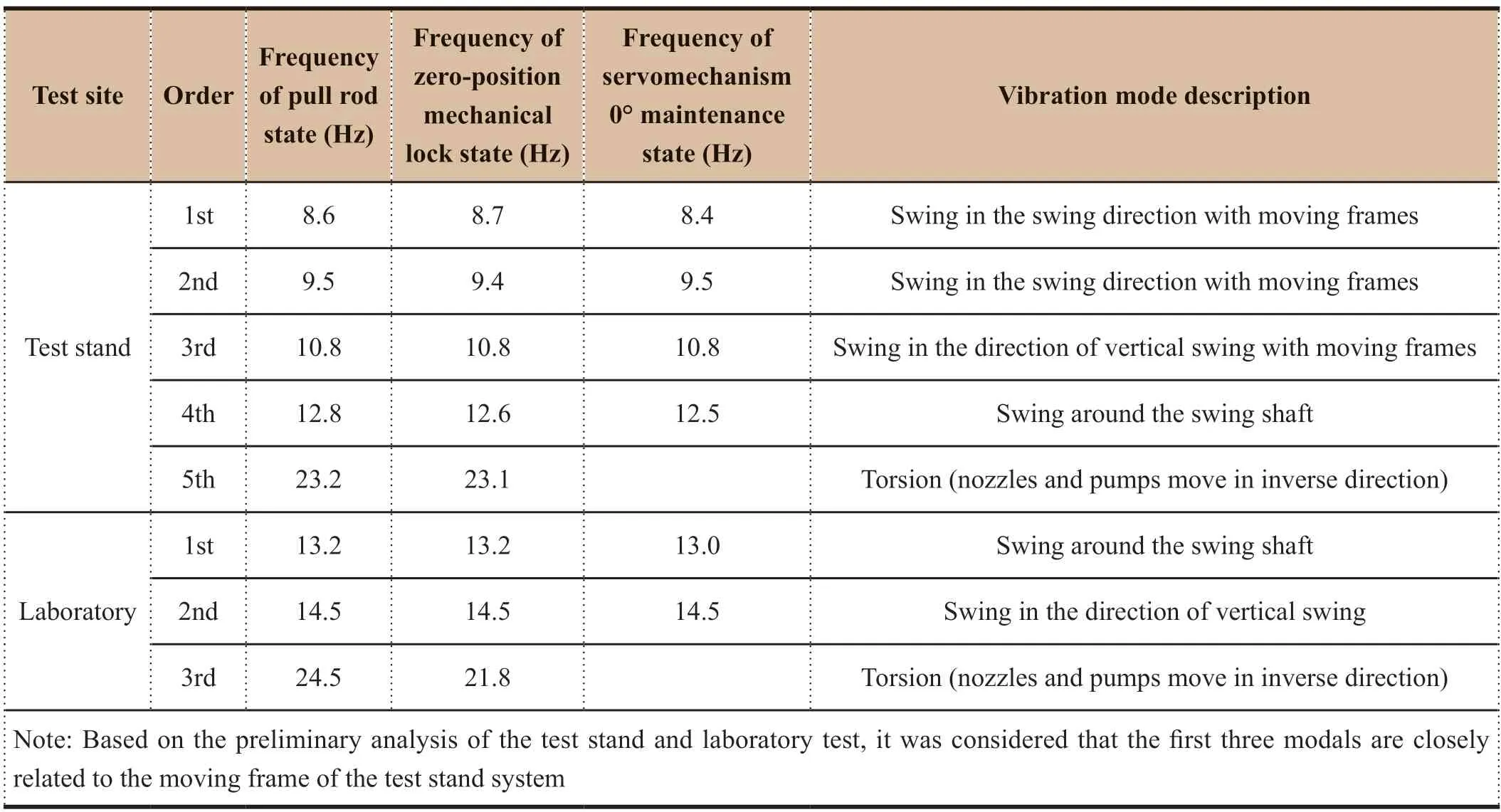
Table 3 Results of engine simulation prediction

Table 3 Results of engine simulation prediction
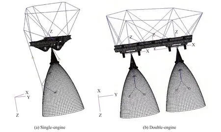
Figure 4 The finite element model of engine
5.3 Modal Test Verification
In order to further verify the practical application impact on the engine structure improvement strategy adopted in this study,modal tests of the single-engine booster engine were conducted under operational conditions in the laboratory and on the test stand,respectively.Based on the analysis of the results of previous modal tests,it was established that the stiffness and mass of the moving and static frames have a considerable influence on the test results,which affects the analysis and determination of the results.Moreover,the boundary condition of the test stand cannot guarantee an absolute rigid support condition for the end face of the frame so the modal verification test with the frame of which the upper end is fixed should be considered.At the same time,the next improvement scheme was determined according to the test results,which provided data support for the establishment of the dynamic characteristic simulation model of engine structure.
The test method was to invert the engine and the frame on the ground,then connect the engine frame and the platform to ensure the rigid condition of the boundary,as shown in Figure 5.

Figure 5 Laboratory modal test
The modal test results are shown in Table 4.It can be seen that the results of the modal test on the test stand are influenced by the test stand system,therefore the first two frequencies are lower.The first-order frequency in laboratory has obviously been improved,but the working state of the servomechanism was slightly reduced,which indicates that the boundary condition of the engine and the operational state of the servomechanism have a significant effect on the modal of the engine.
The results in the laboratory were improved greatly when using the reverse fixed support,and it is also confirmed that the boundary condition influences the modal identification.The results also showed that,there are limitations under the condition of the test stand with the top of the frame fixed as the boundary.In order to predict the low frequency characteristics of the engine using the product frame more accurately,the model of the engine needs to be modified with the modal test results from the laboratory.
6 CONCLUSIONS
The main conclusions of this paper are as follows:
1) Reasonable boundary conditions should be chosen to determine the modal of the engine,and measuring points should be set in the key components such as the nozzles,the swing shafts,gimbal mounts,frames and upper and lower fulcrums of the servomechanism,and appropriate excitation methods and parts should be selected,and a multi-channel tester and a three-way sensor should be used to minimize the test deviation.
2) A reasonable test scheme should be determined to accurately test the center of mass and the inertial moment of the engine,which will lay a foundation for establishing the simulation model of the engine.
3) A reasonable simulation model should be established,especially the stiffness of the servomechanism and bearings should be determined accurately.
4) After the simulation model is established,sensitive factors of the engine should be analyzed,so that the selection of key parameters will enable an effective and feasible scheme to be established in theory,and then the test pieces should be fabricated and verified.Hence by perfecting the simulation model,the static design of the engine can be upgraded to a dynamic design,and the low frequency problem can be avoided in the initial development stage of the engine.
5) Five main measures have been taken to solve the low frequency problem of the engine: an integrated design scheme for the frame-gimbal mount was adopted;reduced frame height;increased the angle between the axis of the servomechanism and thrust chamber;increased the stiffness of the gimbal mount of the swing direction;and improve the stiffness of upper and lower fulcrum loop for the servomechanism.
6) Through modal test,simulation calculation,sensitivity analysis,sensitive test verification,structural design improvement,modal test verification and perfecting simulation model process,it was found that the first-order frequency calculation value for the single-engine and double-engine boost engines can meet the general requirements when the top of the frame is fixed as the boundary.
- Aerospace China的其它文章
- Application of Artificial Intelligence in Outer Space Dispute Resolution
- Structural Analysis and Life Prediction of Thrust Chambers For Hydrogen-Oxygen Rocket Engines
- Dynamic Analysis of Launch Vehicle Piping Systems
- 12-Point Leveling Systems for Mobile Platforms and Emergency Plans
- Design of A Hot Redundant Communication Network for Drive Control Systems of Mobile Launch Platforms
- Cooling Technology for Thrust Chamber of LM-5B LOX/kerosene Engine

