Dynamic physical characteristics of DC arc on arcing horn for HVDC grounding electrode line
Yicen LIU(刘益岑),Chenguang YANG(杨晨光),Yujun GUO(郭裕钧),∗,Xueqin ZHANG(张血琴),Song XIAO(肖嵩),Guoqiang GAO(高国强) and Guangning WU(吴广宁)
1 School of Electrical Engineering,Southwest Jiaotong University,Chengdu 611756,People’s Republic of China
2 State Grid Sichuan Electric Power Research Institute,Chengdu 610041,People’s Republic of China
Abstract The dynamic physical characteristics of a DC arc on an arcing horn for a high voltage direct current(HVDC)grounding electrode line are significantly different from those of the switching device arc,secondary arc,AC fault arc and pantograph-catenary arc.In this work,an experimental platform for the DC arc on the arcing horn was built,and mechanisms of the arc column short circuit and arc root movement were studied.This work further analyzes the characteristics and mechanisms of the arc motion when wind speed and direction,magnetic field and the expansion angle of the electrode are varied.Arc root movement is more likely to occur at the upper electrode.There is a competitive relationship between arc expansion and the transferring effect.The effect of wind on the arc column is greater than the effect on the arc root.The magnetic field has a significant driving effect on both the arc column and the arc root.The research results provide a comprehensive experimental basis for further probing the method of DC arc suppression,and the improvement of the arcing horn.
Keywords:grounding electrode line,arcing horn,DC arc,dynamic physical characteristics
1.Introduction
The development of the Chinese economy and its energy distribution are extremely unbalanced,with load centres and energy bases being far apart,so developing large capacity,long distance,and high voltage transmission technology has become an effective solution to this problem[1].By December 2021,China had established 16 ultra high voltage direct current(UHVDC)transmission projects.
The grounding electrode line is an important part of a high voltage direct current(HVDC)transmission system,as it provides a grounding channel for unbalanced current,and operating current when the HVDC runs at ground return operation mode[2].The use of a grounding electrode line offers important benefits to the lightning performance for both extra high voltage direct current(EHVDC)and UHVDC transmission projects,as described in IEEE Technical Report 62.If the grounding electrode line is struck by lightning,and string parallel gap breakdown is caused by overvoltage impulse,the grounding current will form a persistent current along the lightning discharge channel,which damages the insulation of the line and seriously threatens the safety of the HVDC transmission system.Usually,the insulator string of the grounding electrode line is installed at both ends with an arcing horn,which leads the arc away from the insulator string,thus protecting the insulator string and ensuring the normal operation of the HVDC system[3].The insulator string and arcing horn of the grounding electrode line are shown in figure 1.However,since there is no periodic zerocrossing point of the DC current,the arc formed by the persistent current of the grounding electrode line is difficult to extinguish,which in turn causes serious ablation to the insulators and hardware,causing faults such as conductor fracture and string disintegration.The grounding electrode lines of the±500 kV Yi-Mu HVDC transmission project and the ±800 kV Bin-Jin UHVDC transmission project failed to extinguish the arc in time after the breakdown of the arcing horn gaps occurred,resulting in the insulator and the wire being burned and falling off[4,5],as shown in figure 2.This seriously affected the normal operation of the power transmission channel.
The arcing horn has the function of lengthening and transferring the arc,thus protecting the insulator and the grounding electrode line,which is important in ensuring the safe and reliable operation of the HVDC transmission system.The DC arc on the arcing horn in open space is influenced by the electrode type,environment and other factors,and its movement process is extremely complex.Therefore,it is necessary to study the dynamic physical characteristics of the DC arc on the arcing horn carefully,to explain the motion characteristics of the long-gap DC arc in open space.The research results provide a comprehensive experimental basis for improving the performance of the arcing horn and its ablation resistance,and for developing an arcing horn suitable for the HVDC system.
An arc is a complex physical phenomenon that is usually affected by multiple forces during its motion.Due to the small mass of the arc,even a small force will change its state of motion.A large amount of research has been carried out worldwide on the motion characteristics of arcs,mainly focusing on switching device arcs,secondary arcs,AC fault arcs and pantograph-catenary arcs.The switching device arc is in a closed space,such as splitter plates[6].The motion characteristics of the switching device are different from the arc in open air.In terms of the arc fault of the transmission line,it is mainly for AC arcs such as secondary arcs[7–10].Its electromagnetic environment is different from that of a DC arc.Due to the strong airflow environment,the development characteristics of the pantograph-catenary arc are completely different from that of the DC arc[11–13].In addition,pollution flashover under different pollutions,such as ice,snow and contamination,were studied[14,15].But the arc characteristics of pollution flashover are different from the air-gap arc on the arcing horn.
In this work,the experimental platform was built for the DC arc on the arcing horn,the arc motion characteristics were studied,and mechanisms of arc column short circuiting and arc root movement during arc movement were studied.The characteristics of arc motion and its influencing mechanism were analyzed under different wind speeds and directions,magnetic field and the expansion angle of the electrode.The results of the study provide a comprehensive experimental basis for further probing the method of DC arc suppression,and the improvement of the arcing horn.
2.Characteristics of the DC arc on the arcing horn
2.1.Experimental platform and test method
Figure 3 shows the experimental platform for a DC arc at the arcing horn.The experimental platform mainly consists of a DC power supply,two arcing horn electrodes,a high voltage probe,a current sensor,an oscilloscope,a high speed camera,a ND filter and an arc-inducing wire.The DC power supply has an output current range of 0–150 A and an output voltage range of 0–1500 V.It can be operated in constant current mode.The high voltage probe model P6015A and the current sensor model CT6846-05(0–20 kHz)are used to measure arc voltage and current waveforms via the oscilloscope mode MDO3012.The high-speed camera model FASTCAM Nova S6 is used to record the arc movements and transmit them to the PC.A light filter(ND1000)needs to be added in front of the camera to avoid oversaturation of the light sensor during the experiment.The aperture of the camera needs to be adjusted to a suitable level to prevent string light from affecting the discrimination of the arc.
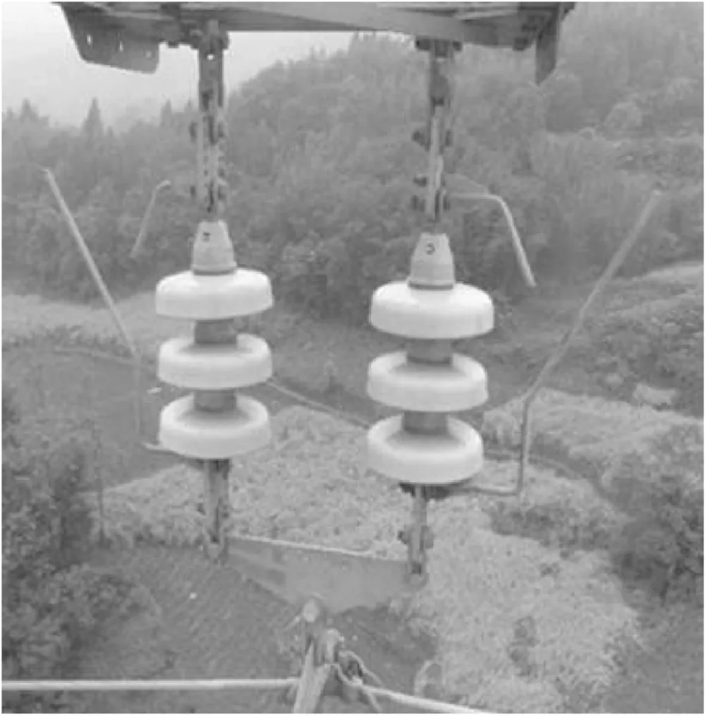
Figure 1.Insulator string and arcing horn of grounding electrode line.
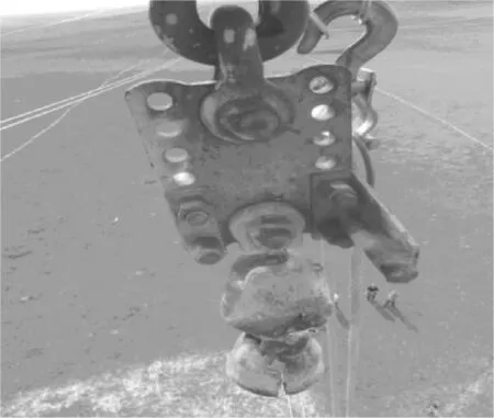
Figure 2.Insulator string and arcing horn after severe burning.
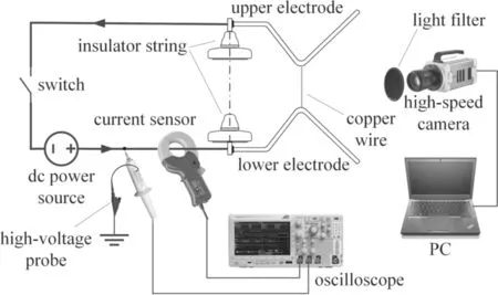
Figure 3.Experimental platform for a DC arc on an arcing horn.
It is difficult to initiate the arc by overvoltage in long gap arc experiments,arc initiation wires are generally used to initiate the arc.According to existing experimental studies,there is no significant difference in the arc motion between the use of arc initiation wire to initiate the arc and the use of overvoltage to initiate the arc;a copper wire of Φ 0.15 mm was used to initiate the arc in this work.
To study the influence mechanism of the DC arc motion on an arcing horn,the wind field,magnetic field and the electrode expansion angle α are varied while keeping the arcing horn distancedconstant.The wind field is generated by an adjustable fan,the magnetic field perpendicular to the electrode plane is generated through a coil.The arc is photographed by the high-speed camera,and the horizontal displacementlcof the arc column and the displacementlrof the arc root are measured,as shown in figure 4.
2.2.Characteristics of the DC arc on the arcing horn
Figure 5 shows the whole process of the DC arc on the arcing horn.The shutter speed of the camera is 1000 fps,that is,every second it takes 1000 pictures,with an interval of 1 ms per frame.The gap distance is 20 cm,the electrode expansion angle is 45°and the DC power source is set to 100 A constant current output.Figure 6 shows the voltage and current waveforms of the DC arc from start to extinguishment.
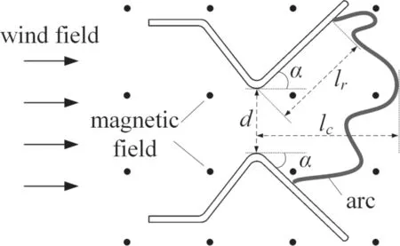
Figure 4.Motion parameters of DC arc on arcing horn.
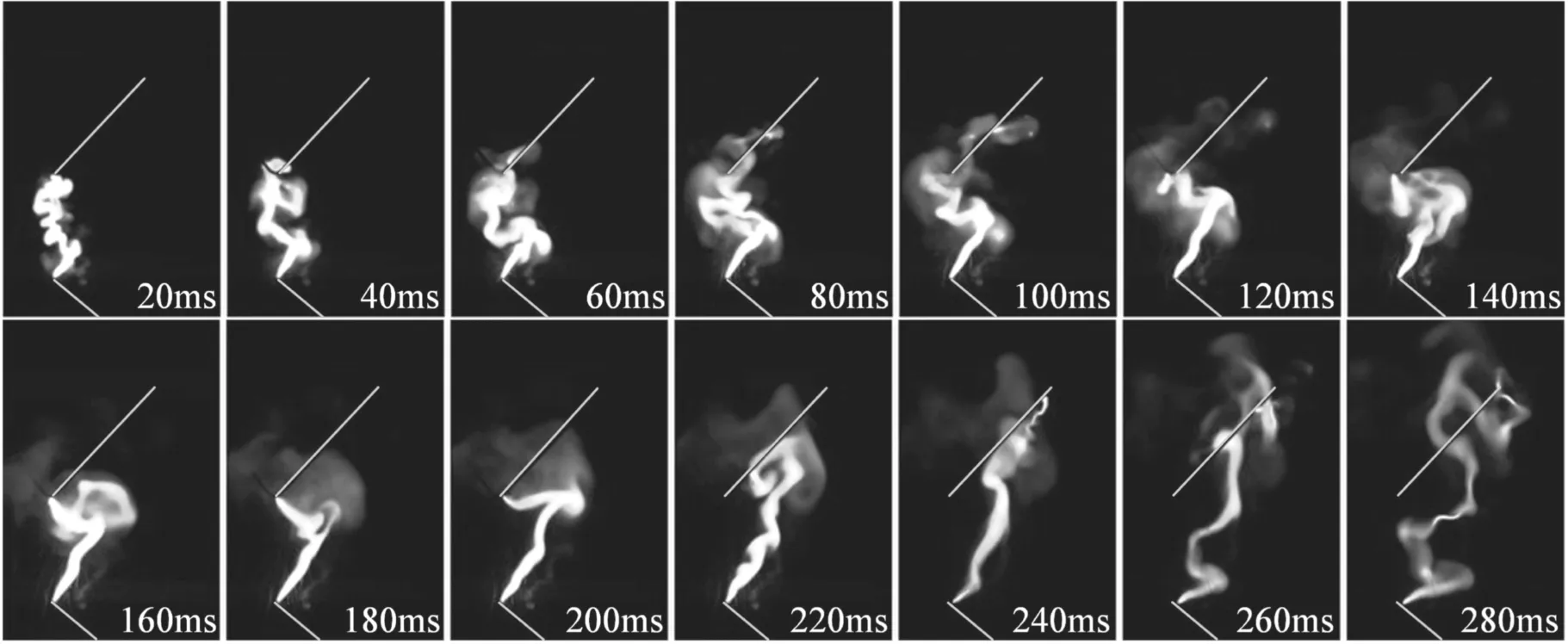
Figure 5.Development process of DC arc on arcing horn.
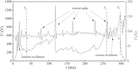
Figure 6.Voltage and current waveforms of DC arc on arcing horn.
As can be seen in figure 5,due to the Joule heat effect generated by the current,the copper wire quickly vaporizes,forming a plasma discharge channel.As the plasma cannot dissipate immediately,the initial arc brightness is high and the overall elongation is not obvious.Each part of the arc moves in a different direction under the action of electromagnetic forces,causing the arc to have extremely irregular distortion.Thereafter,the arc develops in a rightward and upward motion led by the electrode.The electromagnetic force has a major effect on the arc motion,the electromagnetic force at the arc root is larger,so the velocity of the arc root is faster than that of the arc column.The arc drifts upward and continues to elongate,and the voltage increases.When the arc length reaches its limit,the voltage rises,the input energy cannot maintain the burning of the arc,and the arc is then extinguished.
As shown in figure 6,the arc voltage and current change regularly with the motion of the arc.In general,the arc stretches longer and the voltage tends to increase under the expansion and transferring effect of the arc horn electrode.When the length of the arc increases to a certain level,the arc column short circuit and arc root movement are more likely to occur,and the length of the arc suddenly decreases,resulting in a voltage drop.The current is negatively correlated with the voltage and fluctuates somewhat.When the voltage dips,the current is often accompanied by a steep increase,forming a pulse.Due to the thermal inertia of the arc,the current waveform generally lags the voltage waveform by 1–2 ms.The arc movement can be divided into three phases:
(1)0–t1:initial stage.Initially,once the arc has started,the arc moves at a small speed and no obvious displacement occurs.The arc column is influenced by its own magnetic field and the direction of movement of each part is random,resulting in distortion.At this stage,the arcing horn gap is distributed with a large amount of plasma that cannot be dissipated,charged particles,high-energy neutral particles,and copper vapor fill the gap,resulting in frequent short-circuiting of the arc column,causing the arc current oscillation.The oscillation range is 33–133 A,about 30%–70% of the current amplitude.The voltage and current have opposite trends,as the arc voltage increases with arc elongation while the current decreases because of increased arc resistance due to the diffusion of plasma.Once the arc column has a short circuit or the arc root moves,the arc resistance decreases,the current increases instantaneously and the voltage drops.
(2)t1–t2:development stage.The velocity of the arc increases under the action of electromagnetic forces.The arc root moves towards the end of the electrode,the arc column also moves in the electrode expansion direction.The arc is expanded upwards and forward by thermal buoyancy and electromagnetic forces,and the arc length increases.When the voltage reaches 612 V,the arc root moves and the arc length decreases significantly,then the voltage drops to 187 V rapidly with a steep increase of the current to 187.5 A,resulting in a pulse.After that,the arc continues to expand,the voltage generally maintains an upward trend,during which several arc column short circuits and arc root moves occur,resulting in a voltage drop and a steep increase in current.Byt2(260 ms),the cathode arc root reaches the end of the electrode,the arc voltage reaches 745 V,and the current is reduced to 87 A.
(3)t2–t3:maintenance stage.The arc has been stretched to a sufficient length and the arc voltage has increased to a certain degree.The gap is filled with a large amount of plasma,the arc column is extremely unstable,the arc voltage and current fluctuate.Att3(298 ms),the arc voltage reaches a peak of 1101 V and the current reduces to 72 A.During this period,the arc has been sufficiently expanded,the shape of the arc is extremely irregular,the distance between a certain two sections of the arc column or between the arc column and the electrode is too small to be prone to the arc column short circuit or arc root movement,resulting in an unstable arc current.There is a large oscillation,but the overall trend of current is down.
(4)t3–314 ms:extinguishing stage.The input energy is not sufficient to maintain the arc,its brightness is rapidly reduced and the arc extinguished until the 314 ms current is reduced to 0.In this stage,the compounding and diffusion of electrons and ions in the plasma are strengthened,deionization exceeds ionization,the gap insulation is restored and the voltage returns to the supply voltage.The recovery process takes about 20 ms.
2.2.1.Mechanism of the DC arc root movement.Due to thermal buoyancy,the arc has a tendency to move upward,making the arc column closer to the upper electrode.As the arc length increases,when the voltage of the arc column is high enough,air breakdown is likely to occur,forming a new arc root.Figure 7 shows the process of arc root movement;the corresponding moments are marked in the picture.The arc root R on the upper electrode moves towards the end of the electrode end,and the arc column as a whole drifts upwards and spreads out in an irregular shape near the upper electrode.One section of the arc columns gradually approaches the electrode,eventually leading to breakdown and the formation of a new arc root R′ at 117 ms.As can be seen from the change in brightness,the density of the plasma near the electrode gradually increases.After R′ is formed,it exists in parallel with the original arc root R for 2–4 ms,after which the brightness of R gradually decreases until it disappears.During this process,current transfer occurs between the two arc roots.As the arc root moves from the end of the electrode to near the middle of the electrode,the arc length decreases and the voltage drops from 745 to 513 V.At the same time,the current rises from 81 to 137 A due to the reduction of the arc resistance.

Figure 7.Process of arc root movement.

Figure 8.Process of arc column short circuit.
2.2.2.Mechanism of the DC arc column short circuit.During the movement of the DC arc on the arcing horn,due to the bending and deformation of the arc column,it is very easy for two nonadjacent arc columns to come close together,thus leading to a short circuit.Figure 8 shows the process of arc column short circuit,and the numbers in the figure represent the corresponding moments.The arc has bent significantly and has an overall upward trend,with the main part of arc column A closer to the upper electrode.The two sections of arc columns e and f are gradually approaching and short circuit at 172 ms.As can be seen from the change in brightness of the arc,the density of the plasma between arc columns e and f gradually increases until a stable discharge channel is formed and a new arc column A′ is formed eventually.Since the original arc column A is not immediately extinguished,arc columns A and A′ are present at the same time.The brightness of arc column A′gradually increases while the brightness of arc column A gradually decreases due to current shunt and transfer from A to A′ due to a lower arc resistance.The arc current rapidly increases from 87.5 to 134 A,and the voltage drops from 338 to 229 V due to the reduced arc length.Thereafter,arc column A gradually dissipates,and arc column A′ is much brighter and larger in diameter than arc column A,eventually replacing arc column A as the new arc column.
3.The influence mechanism of the DC arc on the arcing horn
3.1.The expansion angle of the electrode
The expansion angle of the electrode has a significant effect on the motion of the arc.Figure 9 shows the arc column displacement curves for electrode expansion angles of 15°,30°,45°and 60°,respectively.The arc moves away from the initial position along the electrode expansion direction.As the expansion angle increases,the velocity of the arc column decreases.When an arc column short circuit or arc root movement occurs,the arc column displacement tends to decrease.Analysis of figure 10 reveals that as the expansion angle increases,the arc root motion speed increases,and the frequency and amplitude of arc root movement also increase,indicating that the arc stability decreases as the expansion angle increases.The average velocities of the arc column and arc root at the electrode expansion angles of 15°,30°,45°,and 60°,respectively,are shown in figure 11.
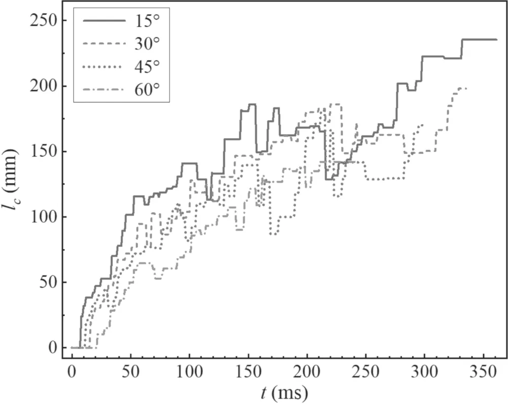
Figure 9.Displacements of the arc column at different expansion angles.

Figure 10.Displacements of the arc root at different expansion angles.
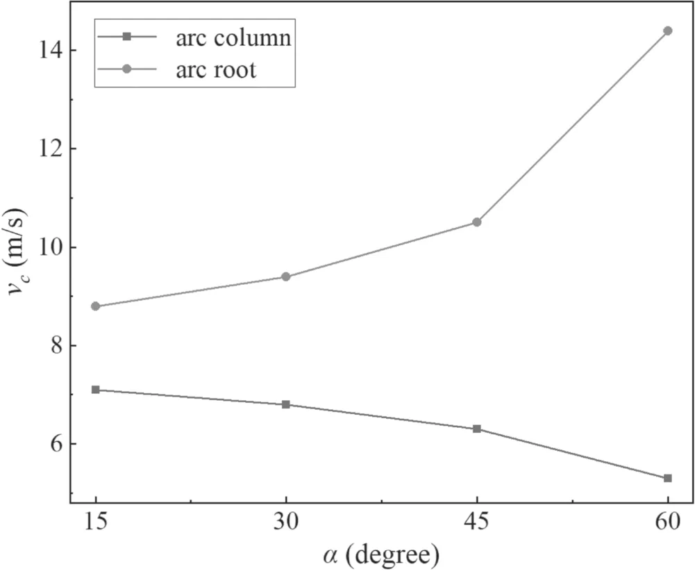
Figure 11.Velocities of arc column and root at different expansion angles.
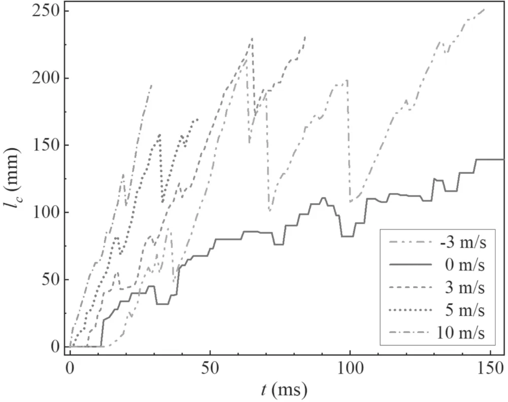
Figure 12.Displacements of DC arc column at different wind speeds and directions.
As the electrode expansion angle increases,the angle between the vertical direction of thermal buoyancy and the direction of electrode expansion decreases,and the combined force of electromagnetic and thermal buoyancy increases.Therefore,the force on the arc root increases and the velocity increases.The arc root moves faster than the arc column,so the arc root plays a pulling effect on the arc column.For electrodes with large expansion angles,the stretching of the arc root on the arc column is stronger in the vertical direction,and for electrodes with small expansion angles,the stretching of the arc root on the arc column is stronger in the horizontal direction.Therefore,as the expansion angle increases,the horizontal velocity of the arc column decreases,suggesting that the arcing horn has a diminished effect on arc sparing and the ability to transfer the arc to move away from the starting position is less with increasing expansion angle.Therefore,as the expansion angle increases,the horizontal displacement velocity of the arc column decreases,indicating that the transfer effect of the arcing horn decreases,and the ability to transfer the arc to the end,in order to move away from the starting position,is smaller with the increase of the expansion angle.
As the expansion angle increases,the horizontal velocity of the arc column decreases,making it easier for the arc column to move closer to the electrode.The charged and energetic particles in the arc plasma are distributed around the electrode,resulting in reduced air insulation strength,triggering a higher probability of air breakdown,and a higher likelihood of arc root movement.It was found that the frequency and amplitude of arc root movement increased with the increase in the expansion angle.The average frequency of arc root movement was 1.8,2.5,3.3 and 4.4 times,and the average amplitude was 79 mm,98 mm,113 mm and 190 mm when the expansion angles were 15°,30°,45° and 60°,respectively.
An increase in the expansion angle of the electrode leads to a stronger arc stretching,but a lower arc transferring effect,so there is a competitive relationship between the two.It can be seen from the figure that near the expansion angle of 45°,there is a clear inflection,so the choice of 45°can take into account the arcing horn on the expansion performance and transferring performance of the arc.
3.2.Wind speed and direction
The arcing horn is installed at both ends of the insulator string of an overhead grounding electrode line,in an open space at a height of 30–50 m.The DC arc on the arcing horn is greatly influenced by wind in the actual environment as the wind speed increases with height above the ground.As can be seen from figure 12,the higher the wind speed,the greater the arc column speed in downwind conditions.The average velocity of the horizontal direction of the arc column was −17.1,5.7,27.3,36.7,66.9 m s−1at wind speeds of −3,0,3,5,10 m s−1,respectively.Figure 13 shows the arc development at wind speed −3 m s−1(upwind).It can be seen that the arc column has been blown to the left of the gap,but the arc root movement does not appear to be affected and still moves along the electrode expansion direction.Therefore,in the case of upwind 3 m s−1,the arc column is subjected to less electromagnetic force than the wind load,and the arc column moves in the opposite direction,but its speed is less than that in the case of downwind 3 m s−1due to the offset of electromagnetic force.The impact of wind on the arc column is greater than the impact of the arc root,which is more influenced by electromagnetic forces.

Figure 13.Development process of DC arc on arcing horn at wind speed −3 m s−1(upwind).
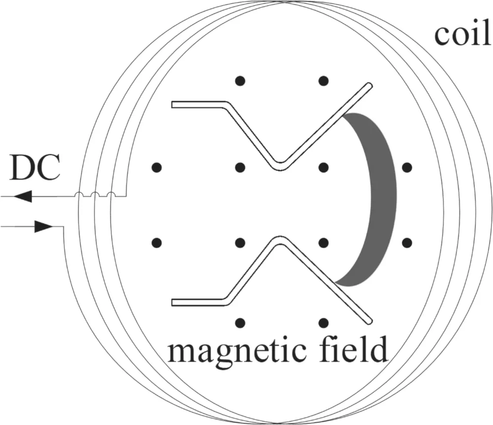
Figure 14.External magnetic field generator.
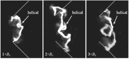
Figure 15.Images of DC arc at different external magnetic fields.

Table 1.Average velocities of arc column and arc root under different magnetic fields.
The drop inlcdecreases as the wind speed increases because the arc plasma is easily blown by the wind.The frequency and amplitude of the arc root movement and arc column short circuit are reduced.The arc burning time was 148,298,85,49,26 ms at wind speeds of −3,0,3,5,10 m s−1,respectively.Wind accelerates the arc cooling,which makes the arc dissociation weaker and reduces the arc dissociation and enhances the compounding effect of electrons and ions.
3.3.Magnetic field
The magnetic field is the main factor influencing the DC arc on the arcing horn.When the DC arc is burning on the arcing horn,the grounding current of the HVDC system passes through the overhead grounding conductors on both sides of the insulator string,and the arc current flows into the Earth through the hardware,the cross-arms and the tower body.These currents form a cross magnetic field at the gap,driving the arc towards the direction of electrode expansion,so that the arc moves away from the insulator string to avoid the ablation of insulators and hardware.
In order to study the effect of magnetic field on the DC arc,a magnetic field generating device is designed in the experiment by injecting DC into the multi-turn coil to establish a magnetic fieldBzin the gap,with the direction of the field vertical to the plane where the arcing horn is located,as shown in figure 14.The strength of the magnetic field is proportional to the number of ampere-turns,so changing the number of coil turns can change the magnitude of the magnetic field.In this experiment,the coil has a diameter of 60 cm,and the current passed is 100 A.
Figure 15 shows the images of the arc at different magnetic fields from 50 ms after the arc start.As can be seen from the figure,the magnetic field has a clear driving effect on the arc.The larger theBz,the more dispersed the arc plasma,the less brightness and diameter,and the horizontal displacement increases to 89,116,141 mm respectively.The arc column is a spiral,and the radius of the spiral increases with the magnetic field,which not only strengthens the expansion of the arc,but also accelerates the involvement of the surrounding cold air,cooling the plasma temperature more rapidly.The arc root is subjected to electromagnetic force more obviously,and the angle between the arc root and the electrode increases with the increase of the magnetic field due to its force direction pointing to the electrode,and the arc root is almost parallel to the electrode at 3×Bz.Figure 16 shows that the greater the magnetic field intensity,the longer the arc column moves.The average velocities of arc roots are also increased by the action of the magnetic field,as shown in table 1.
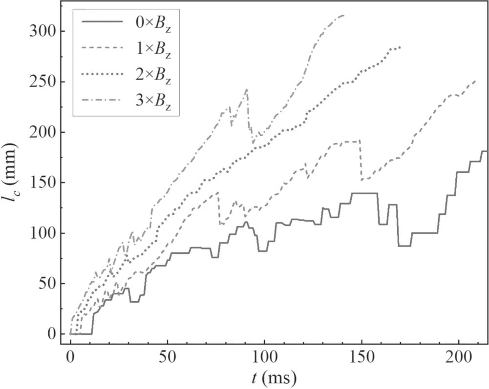
Figure 16.Displacements of DC arc column at different magnetic fields.
4.Conclusions
(1)The DC arc on the arcing horn comprises four stages:initiation,development,maintenance and extinguishment.During the initial and extinguishing phases,the arc current oscillates at a rate of 30%–70%of the current amplitude.The arcing horn has the function of lengthening and transferring the arc.During the arc movement,arc column short-circuiting and arc root movement occur frequently,causing voltage dips and current pulses.Due to the thermal buoyancy,the arc as a whole is shifted upward and arc root movement is more likely to occur at the upper electrode.
(2)The larger the electrode expansion angle,the greater the longitudinal expansion effect on the arc,but the smaller the transferring effect.Therefore,the larger the expansion angle,the more likely the arc column is to be close to the electrode,the higher the probability of breakdown between the arc column and the electrode,and the more likely it is to trigger arc root movement.The arc root movement frequencies were 1.8,2.5,3.3 and 4.4 for expansion angles of 15°,30°,45° and 60°,respectively,with average movement amplitudes of 79,98,113 and 190 mm.An expansion angle of 45°can take into account the expansion and transferring performance of the arcing horn.
(3)Wind has a significant effect on arc motion,affecting the arc column more than the arc root.The average velocity of the horizontal direction of the arc column was 5.7,27.3,36.7,66.9,−17.1 m s−1at 0,3,5,10,−3 m s−1wind speed,respectively.Increased wind speed accelerates the diffusion and cooling of the arc plasma,making the arc easier to extinguish.The higher the wind speed,the less the arc root moves and the arc column short circuits.Wind has less of an effect on the arc root,which still moves in the direction of electrode expansion in upwind conditions.
(4)The magnetic field has a strong driving effect on both the arc column and the arc root.Due to the electromagnetic force,the direction of force points to the electrode.The larger the magnetic field,the smaller the angle between the arc root and the electrode.The arc column is a spiral,and the radius of the spiral increases with the increase in electromagnetic field.
Acknowledgments
This work is supported by National Natural Science Foundation of China(No.51907168),funded by Sichuan Science and Technology Program(Outstanding Youth Science and Technology Talents)(No.2020JDJQ0039).
ORCID iDs
 Plasma Science and Technology2023年1期
- Plasma Science and Technology的其它文章
- Quasi-coherent mode in core plasma of SUNIST spherical tokamak
- High-resolution x-ray monochromatic imaging for laser plasma diagnostics based on toroidal crystal
- Numerical study of viscosity and heat flux role in heavy species dynamics in Hall thruster discharge
- Development of miniaturized SAF-LIBS with high repetition rate acousto-optic gating for quantitative analysis
- A study of the influence of different grid structures on plasma characteristics in the discharge chamber of an ion thruster
- Focused electron beam transport through a long narrow metal tube at elevated pressures in the forevacuum range
