Bearing Capacity Research of Reinforced Gravity Retaining Wall
YIN Lili, WEN Hua, LI Kunpeng
(School of Civil Engineering and Architecture, Southwest University of Science and Technology, Mianyang,Sichuan 621010, China)
Abstract: This study examines the effects of reinforcement position and section size on the bearing capacity of reinforced gravity retaining walls with varyingly designed and implemented section sizes and reinforcement positions.To obtain the effect of the reinforced gravity retaining wall’s reinforcement position on the bearing capacity of the retained wall, the bearing capacity of the reinforced gravity retaining wall behind the retained wall section was evaluated.The test results demonstrate that under the same top load of the soil behind the wall, the bearing capacity of the reinforced gravity retaining wall with the smaller cross-sectional area was increased by 15.67% than that of the reinforced gravity retaining wall.It has been demonstrated that when the geogrid’s position increases, the resistance decreases and the anti-overturning moment increases.The top section of the reinforced gravity retaining wall’s reinforcement has a bearing capacity that was 34.91% and 24.71% higher than the bearing capacity that the middle and lower sections of the reinforcement can withstand, respectively.
Keywords:geogrid;gravity retaining wall;reinforced gravity retaining wall;reinforcement height;bearing capacity
0 Introduction
A gravity retaining wall is a retentive structure[1]that maintains stability and balance by resisting soil pressure through gravity.A gravity retaining wall is usually built by block stone or concrete, which are convenient for construction, and are currently the most widely used materials.Gravity retaining walls require large weight and volume because their weight maintains the balance and stability.The cost of a wall increases with its height because more materials are needed[2].To overcome the defects of gravity retaining walls, Zou et al.[3]improved the strength of the filler by combining it with the reinforced material to form the gravity-reinforced soil retaining wall, which can prevent gravity retaining wall from deformation.This can prevent the issue of the gravity retaining wall from being easily rotated while also making it possible to fully utilize the benefits of the reinforced material and the gravity retaining wall.Yang et al.[4]proposed integrating reinforcement technology into the application of gravity retaining walls by introducing reinforcement technology to the classic gravity retaining wall to form a reinforced gravity retaining wall.
The stability of the gravity retaining wall was improved by adding reinforcement materials to the upper section, which increases the anti-overturning moment of the wall through friction with the soil.To interact with the fill behind the wall, the reinforcement materials are also extended into the wall[4].Qiu et al.[5]observed that, when compared to gravity retaining walls, reinforced gravity retaining walls requiring less masonry have better seismic performance, and have lower foundation bearing capacity requirements.
The realization of positive results has increased interest in the research on gravity retaining walls and their bearing properties in recent years.The majority of these studies, however, concern the effects of earth pressure, infill behind the wall, and geogrid materials.Few studies focus on reinforced gravity retaining wall reinforcing parameters and section size reduction.The contribution of this paper is significant to innovation in reinforced gravity retaining walls with a variety designed and implemented section sizes and reinforcement positions.
To provide a theoretical foundation for the design of reinforced gravity retaining wall, this paper investigates the effects of reinforcement position and reinforcement length of reinforced gravity retaining wall as well as analyzes the bearing performance of reinforced gravity retaining wall with smaller section size.
1 A description of the reinforced gravity retaining wall test
1.1 Design and fabrication of test model
The prototype of a gravity retaining wall has a slope ratio of 1∶0.2 and measures 5 000mm in height, 1 200mm in width, and 2 200mm in width.The scale model’s geometric closeness to the original model was 1∶5, while the ratios for the stress, the uniformly distributed surface force load, and the internal friction angle were 1∶16, 1∶16, and 1∶1 respectively.
1)After reducing the portion of the retaining wall, the gravity retaining wall and a reinforced gravity retaining wall were constructed.With a slope ratio of 1∶0.2, Fig.1 shows the ordinary gravity retaining wall along with a 2/3 section area gravity retaining wall(unreinforced)and a 2/3 section area reinforced gravity retaining wall.

Fig.1 The test structure of gravity retaining wall and reinforced gravity retaining wall
2)Reinforced gravity retaining wall at different reinforced positions
Fig.2 depicts three gravity retaining walls: a reinforced gravity retaining wall with a reinforcement height of 20cm(the lower reinforcement), a reinforced gravity retaining wall with a reinforcement height of 50cm(the central reinforcement), and a reinforced gravity retaining wall with a reinforcement height of 80cm(the upper reinforcement).These walls have a slope ratio of 1∶0.2 and a geogrid length of 1m.

Fig.2 Reinforced gravity retaining wall at different reinforced positions
Through comparative analysis, the effect of different reinforcement positions on the bearing capacity of the reinforced gravity retaining wall was examined.
1.2 Test model components
1)Indexes of soil physical and mechanical properties behind the wall
The soil used for the test was provided by Tongnan District’s Baolong Town in Chongqing City.The internal friction angle and cohesiveness were evaluated using a direct shear test.A rapid shear test was used to conduct this test, and all relevant specifications were strictly followed.Fig.3 depicts the test procedure.

Fig.3 Direct shear test procedure
In the following calculations, the on-site soil sample internal friction angleφwas 11.75 °, the cohesioncwas 25.18 × 10³Pa, and the severe was set 1 792 N/m3.
2)Gravity retaining wall material
The gravity retaining wall was constructed by MU30 sintered ordinary brick and M10 cement mortar.
3)Geogrid
This test used a geogrid made of high-density polyethylene biaxial tensile plastic, model TGSG50-50 in Jiangsu Jinchong Nonferrous Metal Products Co., Ltd.The geogrid can provide exceptional wear resistance, excellent tensile strength, good stiffness, and a little variation between vertical and horizontal strength.
1.3 The layout of test elements
In this test, the lateral displacement of the wall was measured by 10 dial indicators, and the settlement displacement of the soil behind the wall was measured by 2 displacement meters.Fig.4 shows the layout of dial indicators and displacement meters.
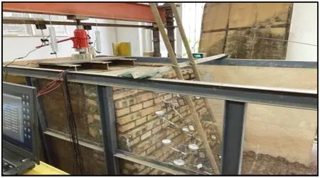
Fig.4 Layout of displacement meters and dial indicators
1.4 Test the loading scheme
In this test, the uniformly distributed load was achieved through the application of the jack and reaction frame, the force transfer plate, and a force transfer frame that are transmitted to the loading plate with a length and breadth of 90cm and a thickness of 20mm.A 10kPa was applied every two minutes using the graduated loading technique, followed by a five minutes rest period.When the soil deformation was stabilized, the lateral displacement of the wall and the topsoil settlement were recorded.The soil will be destroyed if the load is not applied or the soil deformation is too large, hence this load is regarded as the slope’s critical load.Finally, the recorded data was analyzed and a conclusion was drawn.The loading device is shown in Fig.5.
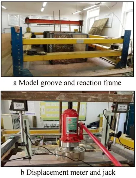
Fig.5 Loading device
2 Test results and bearing characteristics analysis
2.1 Analysis of settlement data for the soil behind the wall
Three groups of foundation tests were set up: ordinary gravity retaining wall, 2/3 section area gravity retaining wall(unreinforced), and 2/3 section area reinforced gravity retaining wall.The results of these tests were used to determine the maximum load when the slope is damaged under the evenly distributed load on the top of the soil behind the wall and the settlement change of the top of the soil.Every time the vertical load on the wall changed, the maximum load at the top of the wall dropped downward, as shown in Fig.6.
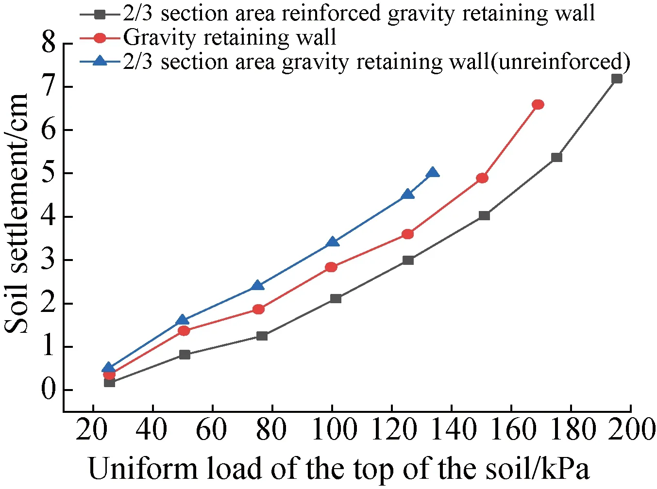
Fig.6 Relationship between load and soil settlement
Fig.6 demonstrates that when the load exceeds 133.5kPa and the soil settlement by 5.03cm, the gravity retaining wall with a section size of 2/3 achieves the limit condition.When the load is 169.7kPa and the soil settlement reaches 6.58cm, the gravity retaining wall achieves its limit condition.The reinforced gravity retaining walls’ 2/3 cross-section had a soil settlement of 4.83cm.When the load becomes 196.3kPa and the soil settlement reaches 7.22 cm, the reinforced gravity retaining wall with a cross-section area achieves its maximum state.
When the load was first applied, compaction raised the soil’s settling value immediately.With soil compaction, the higher amplitude relative becomes less significant.The settlement rapidly transformed as the maximum load was reached.After a 1 m geogrid was constructed at the wall height of 80 cm, the reinforced gravity retaining wall with a reduced cross-section area of 1/3 can bear a greater ultimate load than the traditional gravity retaining wall, and the soil settlement is smaller under the same evenly distributed load.When subjected to the maximum load, the soil settlement of the reinforced gravity retaining wall was 26.6% lower than that of a gravity retaining wall.
2.2 Analysis of the lateral displacement data from the wall test steps
Fig.7 compares the three sets of of foundation tests in terms of the lateral displacement of the wall as measured at the monitoring points in the middle and side of the wall when the retaining wall was applied to each critical load at the top behind the wall.

Fig.7 Relationship between monitoring points and lateral displacement of the wall under critical load
Fig.7 demonstrates that when the load reached 133.5kPa, the maximum lateral displacement of the gravity retaining wall, with a section size of 2/3, was 23.35mm.When the load was 133.5kPa, the gravity retaining wall’s maximum lateral displacement was 18.52mm.A reinforced gravity retaining wall with a cross-section area of 133.5kPa had a 15.25mm maximum lateral displacement.The maximum lateral displacement of the 2/3 section area reinforced gravity retaining wall was 26.24mm, and the maximum lateral displacement of the gravity retaining wall was 28.56mm when the load approached the ultimate load 169.7kPa.
The lateral displacement of the reinforced gravity retaining wall decreases and the load increases when it supports the same evenly distributed load.The lateral displacement of the wall increases as the wall height rises, and the lateral displacement shifts from being slightly larger in the center to being slightly smaller on the side.Subjected to the maximum load of a gravity retaining wall, the lateral displacement of the reinforced gravity retaining wall was 8.12% lower than that of a gravity retaining wall.
2.3 Earth pressure data analysis behind a retaining wall
When the uniformly distributed load behind the wall reaches the critical load of the gravity retaining wall of 169.7kPa, the earth pressure behind the reinforced gravity retaining wall and gravity retaining wall as measured by the earth pressure gauge behind the wall.are shown in Fig.8

Fig.8 Relationship between earth pressure and wall height when the uniformly distributed load was 169.7 kPa
When a load of the reinforced gravity retaining wall and gravity retaining wall reaches 169.7kPa, Fig.8 demonstrates that the maximum earth pressure behind the wall was fairly distributed at the wall height of 33cm.At a wall height of 66.64cm, the geogrid successfully reduces the earth pressure on the reinforced gravity retaining wall.
3 Test results and bearing characteristics analysis of reinforced gravity retaining walls at different reinforcement positions
The three reinforcement positions used in this comparison test are a reinforced gravity retaining wall with a reinforcement height of 20cm, a reinforced gravity retaining wall with a reinforcement height of 50cm, and a reinforced gravity retaining wall with a reinforcement height of 80cm, the slope ratio and reinforcement length are the same.To investigate the effectt of reinforcement position on the bearing performance of reinforced gravity retaining walls, measurements are taken of the settlement displacement of the top of the soil body, the lateral displacement of the retaining wall, the lateral earth pressure of the retaining wall, and the stress and strain of the geogrid.
3.1 Settlement data analysis of soil behind the wall
Fig.9 shows the maximum load at which the slope body was damaged as well as the change in the vertical settlement of the slope top when the reinforced gravity retaining wall was installed at three different reinforced positions.
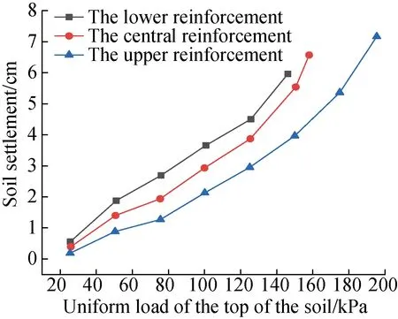
Fig.9 Relationship between load and soil settlement
Fig.9 demonstrates how the reinforced gravity retaining wall with a reinforcement height of 20cm approaches the limit condition when the load reaches 145.5kPa and the soil settlement becomes 5.99cm.When the load reaches 157.4kPa and the soil settlement was 6.65cm, the reinforced gravity retaining wall with a reinforcement height of 50cm achieves its limit condition.When the load reaches 196.3kPa and the soil settlement was 7.22cm, the reinforced gravity retaining wall with a reinforcement height of 80cm achieves its limit condition.The geogrid placed on the upper half of the gravity retaining wall has a greater impact on minimizing soil settlement than reinforcement placed on the middle and lower portions of the wall.This enhances the soil’s ultimate bearing capacity.
3.2 Analysis of lateral displacement data of wall
The maximum lateral displacement of the lower reinforcement and the central reinforcement were 22.64, 20.92mm.The maximum lateral displacement of the upper reinforcement was determined by the lateral displacement of the wall at different reinforcement positions subject to the critical load, as shown in Fig.10, when the uniformly distributed load behind the wall reaches 145.5kPa.

Fig.10 Lateral displacement of the wall at different reinforcement positions under critical load
When the reinforced gravity retaining wall was subjected to the same evenly distributed load, the upper reinforced wall’s lateral displacement was less than that of the middle and lower reinforced walls, and it can support a greater weight.The wall’s lateral displacement increases as the wall height rises and the side of the wall has a smaller lateral displacement than the middle.
3.3 Earth pressure data analysis behind retaining wall
Fig.11 depicts the relationship between the earth pressure behind the wall and the wall height of the reinforced gravity retaining wall at three different reinforcement positions when the load behind the wall is evenly distributed reaches the critical load of the lower reinforced gravity retaining wall, which is 145.5kPa.
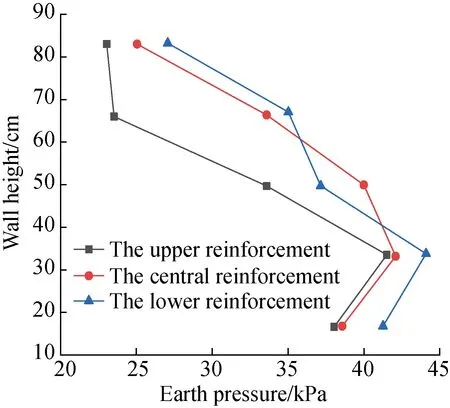
Fig.11 Relationship between earth pressure and wall height with a uniformly distributed load of 145.5kPa
Fig.11 shows that, the maximum earth pressure behind a gravity retaining wall at 145.5kPa was distributed at a height of 33cm, and the pressure increases with depth.However, the action of the geogrid effectively slows the growth of earth pressure near the reinforcement behind the wall of a reinforced gravity retaining wall.The friction between the buried soil in front of the wall and the foundation causes the earth pressure to decrease once it reaches a 33cm high point.
When the reinforcement length were 2, 3, 3.75, 4.7m, the soil settlement value became 7.2, 4.42, 2.5, 1.71dm, respectively.Fig.12 shows how soil reinforcement improves the bearing capacity of soil by decreasing the soil settlement value as reinforcement length increases.
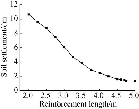
Fig.12 Relationship between reinforcement length and soil settlement
3.4 Analysis of geogrid stress-strain data
The locations of the strain gauges used to identify the geogrid strain are numbered sequentially.Fig.13 depicts the geogrid strain at each reinforced position when the soil load of retaining walls at various reinforced positions reaches 145.5kPa.
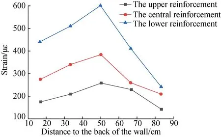
Fig.13 Relationship between geogrid strain and distance to the back of the wall
Fig.13 shows that the maximum strain of the geogrid was 260.88με when the evenly distributed load of the reinforced gravity retaining wall and gravity retaining wall reaches 145.5kPa.When the middle and lower parts were reinforced, the maximum strain of the geogrid became 376.51, 600.79με, respectively.The upper reinforcement’s maximum strain was 30.71%, 56.58% less than that of the middle and lower reinforcements, respectively.
Fig.14 shows the relationship between geogrid displacement and soil settlement, showing that the soil settlement was 7.05cm when the geogrid is 1m from the bottom of the retaining wall and its length was 1/10 of the wall height.The soil settlement value was 4.96cm when the geogrid length reaches 7/10 of the wall height, while the reinforced gravity retaining wall had the best bearing capacity and the smallest soil settlement value when the geogrid length reaches 8/10 of the wall height.
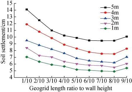
Fig.14 Relationship between geogrid length and soil settlement
4 Conclusions
According to the test results comparing gravity retaining walls and reinforced gravity retaining walls with changed sections, the bearing capacity of reinforced gravity retaining wall with reduced section area of 1/3 was 15.67% higher than that of the regular gravity retaining wall.According to the test results of gravity retaining walls and reinforced gravity retaining walls with changed section, under the ultimate load of gravity retaining wall, the settlement of soil of reinforced gravity retaining wall with 1/3 section area reduced 26.6% lower than that of ordinary gravity retaining wall without reinforcement, and the lateral displacement of the wall was reduced by 8.12%.
Data analysis of the test results of reinforced gravity retaining walls at different reinforcement positions revealed that, when subjected to the same load, there was less soil settlement and wall displacement.The reinforced gravity retaining wall’s upper section had a better bearing capacity than its middle and lower sections, and it can support a higher ultimate load.The upper section’s reinforcement had a bearing capacity that was 24.71%, 34.91% higher than that at the middle and lower sections, respectively.When the cross-sectional area of the retaining wall was 1/2 of that of the gravity retaining wall, a layer of geogrid with adequate bearing capacity was arranged behind the reinforced gravity retaining wall at a wall height of 4/5, and a second layer was arranged at a wall height of 1/2 to 3/5.When the length of the second geogrid reaches 4/5 of the wall height, the reinforced gravity retaining wall with reduced section outperforms the gravity retaining wall.

