Graphdiyne scaffold anchored highly dispersed ruthenium nanoparticles as an efficient cathode catalyst for rechargeable Li–CO2 battery
Yiru M ,Huiqi Qu,d ,Wnn Wng ,Ziyng Guo ,Yuqin Yu ,Fng Liu ,Bin Yu,Ming Tin,Zhnjing Li,Bin Li,∗,Li Wng,c,∗
a College of Chemistry and Molecular Engineering,State Key Laboratory Base of Eco-Chemical Engineering,International Science and Technology Cooperation Base of Eco-Chemical Engineering and Green Manufacturing,Qingdao University of Science and Technology,Qingdao 266042,China
b College of Materials Science and Engineering,Qingdao University of Science and Technology,Qingdao 266042,China
c College of Environment and Safety Engineering,Qingdao University of Science and Technology,Qingdao 266042,China
d College of Chemical Engineering,Qingdao University of Science and Technology,Qingdao 266042,China
e Biomedical Sensing Engineering Technology Research Center,Shandong University,Ji’nan 250100,China
f Scientific Green (Shandong) Environmental Technology Co.,Ltd.,Jining Economic Development Zone,Jining 272499,China
Keywords:Nanopores Li–CO2 battery Anchored Ru nanoparticles Graphdiyne Synergistic effect
ABSTRACT Lithium (Li)–CO2 battery is rising as an attractive energy-storage system with the competence of CO2 conversion/fixation.However,its practical development is seriously hindered by the high overpotential.Herein,a rational design on a highly catalytic Li–CO2 battery electrode built by graphdiyne powder as a multi-functional laminar scaffold with anchored highly dispersed Ru nanoparticles is explored.The strong interaction between the abundant acetylenic bond sites of graphdiyne scaffold and Ru nanoparticles can effectively promote the electrochemical progress and reduce the voltage polarization.The unique channels architecture of the cathodic catalyst with enough space not only accelerates CO2 diffusion and electrons/Li+ transport,but also allows a large amount of accommodation for discharged product (Li2CO3)to assure an advanced capacity.The corresponding Li–CO2 battery displays an advanced discharged capacity of 15,030 mAh/g at 500 mA/g,great capacity retention of 8873 mAh/g at 2 A/g,high coulombic efficiency of 97.6% at 500 mA/g and superior life span for 120 cycles with voltage gap of 1.67 V under a restricted capacity of 1000 mAh/g at 500 mA/g.Ex/in-situ studies prove that synergy between Ru nanoparticles and acetylene bonds of GDY can boost the round-trip CO2RR and CO2ER kinetics.
“Greenhouse effect” generated by the massive exploitation of fossil fuels poses severe challenges to environmental protection[1–4].Recently,Li–CO2battery is attractive energy storage device,which creates an innovative path for converting CO2gas from external space to produce renewable energy [5–8].The electrochemical reaction of a classical rechargeable Li–CO2battery is 4Li+3CO2↔2Li2CO3+C [9–11].Although Li–CO2battery has been widely researched and evaluated,there are still many challenges to be overcome before the actual application.The major challenge is Li2CO3,as an insulator product with wide gap in CO2reduction reaction (CO2RR) [12–14],not only affects the next mass transfer process,but also causes the electrolyte oxidized due to a high overpotential in the CO2evolution reaction (CO2ER) process [15–17].Thus,developing an efficient catalyst with excellent catalytic performance and optimized structure is the key to promoting the performance of Li–CO2battery.
To solve the above problems,great progresses have been made in designing cathodic catalysts for Li–CO2battery using carbon materials (CNTs [18]) and transition-metal based materials (NiO–CNT[19],Mo2C [20]).However,those of reported Li–CO2batteries still have the problems of high overvoltage and short cycle life.Nowadays,noble metal-based materials,especially ruthenium (Ru) have been regarded as the most promising catalysts in promoting the activity of CO2RR and CO2ER due to their unique electronic configuration and prominent electrochemical stability [21].For instance,He and co-workers introduce the Li–CO2battery based Ru@super P cathode,which reduces polarization voltage greatly and accelerates the decomposition of the discharged products [22].Nevertheless,the stability of Ru@Super P-based Li−CO2battery is still restricted,only 70 cycles.To address this issue,Chen and co-workers report Ru nanoparticles functionalized graphene-based Li−CO2battery which displays a charge voltage of ∼4.02 V and a coulombic efficiency of ∼89.2% [23].Despite these advances,the interaction between metal and nano-carbon matrix is so week that the catalytic sites always are easier to fade off [24–27].In addition,the distribution of active sites is difficult to control so that the stability and reversibility of the cells are not satisfied.In order to construct an efficient catalytic system,a scaffold is needed to firmly anchor these metal nanoparticles.Two key points need to be given concern about choosing a proper scaffold.One point is that the number of exposed active sites should be increased.Another important point is that the scaffold should interact strongly with the active site to form a good electronic structure and prevent catalyst deactivation [28–30].Therefore,it is of great significance to reasonably research a Ru metal anchored carbon-based scaffold catalyst possessing an excellent structure and effectively promoting the catalytic kinetics of CO2ER/CO2RR for long-life reversible Li−CO2battery.
Graphdiyne (GDY),a new-type carbon allotrope constituted by highπ-conjugation network of well-organized sp and sp2hybrid carbon atoms [31–33],has been high-profile in many fields such as electrochemistry,photocatalytic,optics and electronics [34,35].The unique structure endows a promising platform for stabilizing metal centers.Meanwhile,the calculation [36] suggests that the coupling between metal and GDY is ascribed to the enhanced chemical adsorption,which could bring about a strong charge transfer between them.Moreover,the topological network with hexagonal voids formed by the three butadiene chains (–C≡C–C≡C–) not only provides a spatially limited framework to prevent metal aggregation,but also is more prone to attract CO2[37,38],which makes a great contribution to the kinetics of CO2ER process for Li−CO2battery.Therefore,it is very promising to combine noble metal and GDY as a cathodic catalyst.
Herein,we select the graphdiyne scaffold (GDYS) with a laminar structure to anchor Ru nanoparticles with a uniform and firm layout.The catalyst is fabricated by acetylene coupling reaction and ethylene glycol reduction treatment.The highly dispersed Ru nanoparticles are anchored on graphdiyne scaffold (Ru-GDYS)which is further served as cathode for Li–CO2battery.The wellconducting and electronic-rich lamellar structure bestows GDY scaffold the capacity to reposit a large number of Li+in Li–CO2battery.The strong coupling between the GDYS and Ru nanoparticles results in a large amount of charge transfer,which can effectively improve the electrochemical activity and reduce the voltage polarization.Meanwhile,Ru-GDYS provides not only large specific surface area and unique triangular pores to improve the fast electrons transportation and facilitate electrolyte infiltration,but also sufficient space for Li2CO3to realize high discharged-capacity.In addition,the highly dispersed Ru nanoparticles serving as rich active sites forcefully facilitate the dynamics of CO2ER/CO2RR.The assembled Li–CO2battery with Ru-GDYS catalyst delivers a large discharged capacity of 15,030 mAh/g at 500 mA/g and superior cycling stability for 120 cycles with voltage gap of<1.67 V.Furthermore,a series of ex/in-situ technologies demonstrate the great reversibility and durability of Ru-GDYS in Li–CO2battery.Therefore,this kind of design opens up a roadway for developing such creative catalysts of advanced performance metal–gas battery.
Fig.1a displays the synthesis procedure for the Ru-GDYS cathode catalyst.GDYS powder is preparedviaacetylene coupling reaction on copper foils (details in Supporting information) [39].Subsequently,GDYS powder and RuCl3·xH2O are uniformly mixed in ethylene glycol solution and then refluxed at 170 °C to anchor Ru nanoparticles on GDYS.Scanning electron microscope (SEM)images (Figs.S1a and b in Supporting information) display that the as-prepared GDY scaffold possesses a uniform and continuous lamellar structure.SEM images (Figs.S1c and d in Supporting information) show that,the GDY scaffold exhibits a threedimensional continuous network with lots of voids,which is composed of multiple layers.Transmission electron microscopy (TEM)images (Fig.1b and Fig.S2a in Supporting information) of GDY scaffold confirm that they have typical two-dimensional folded lamellar-like structure,in which the stacking of GDY layers can be seen at the edges.It should be noted that Ru-GDYS could remain the original lamellar morphology (Fig.1c),suggesting that the high-temperature reduction treatment does not break the basic framework of GDY.What is more,there are a mass of voids over the Ru-GDYS either (Fig.1d).The TEM images (Fig.1e and Fig.S2b in Supporting information) of Ru-GDYS reveal that the small Ru nanoparticles are encapsulated between the GDY layers.From the high-resolution (HR) TEM images (Fig.1f),the size of Ru nanoparticles is mostly less than 5 nm with lattice fringes spacing of 0.233 nm,which is related to the distances of Ru (100)crystal face.Moreover,it can be distinctly distinguished the lattice fringes of the well-crystallized GDYS layered backbone,with an interlayer space of 0.365 nm (Fig.1g).The selected area electron diffraction (SAED) further proves the existence of Ru species with polycrystalline nature (Fig.1h).There are three diffraction rings in SAED image,associated with the (100),(102) and (110)lattice planes of Ru metal,indicating that the obtained Ru-GDYS sample is polycrystalline.The energy dispersive X-ray spectroscopic(EDS) elemental mapping (Fig.1i) of Ru-GDYS demonstrates that the distributed Ru elementals are situated homogeneously in the all-carbon network,indicating the successful combination of Ru−C sites in GDYS.Besides,the existence of O element is as a result of the absorption of O2from air.To optimize the content of Ru nanoparticles loading,Ru-GDYS composites with different Ru contents (4.2,9.0 and 15.2 wt%) have been synthesized by adjusting the initial mass of RuCl3.Inductively coupled plasma-optical emission spectroscopy (ICP-OES) analysis (Table S1 in Supporting information) and TEM technology (Fig.S3 in Supporting information)are executed to characterize the three samples.In followed battery tests,the Ru-GDYS catalyst with 9.0 wt% shows the best cycling performance (Fig.S4 in Supporting information).Therefore,the Ru content is optimized to be around 9.0 wt%.
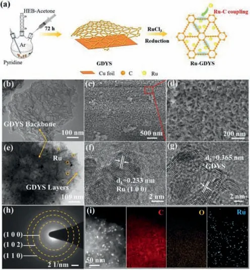
Fig.1. (a) The preparation steps for Ru-GDYS.(b) TEM image of GDYS.(c,d) SEM images of Ru-GDYS.(e) TEM image and (f,g) HR-TEM images of Ru-GDYS.(h) SAED pattern of Ru nanoparticles.(i) EDS mapping images of C,O and Ru elements,respectively.
The X-ray diffraction (XRD) pattern of GDYS exhibits a broad peak at around 22.8°,matched with the typical interlamellar spacing of 0.365 nm (Fig.2a).There is also a week and broad diffraction peak around 42.7° related to disordered carbon materials.Notably,XRD pattern of the Ru-GDYS catalyst reveals five typical peaks of Ru,which are located at 38.3°,42.2°,43.8°,58.2°and 69.1°.These results demonstrate that Ru nanoparticles are successfully anchored on carbon material.Defects/disorder carbon(D-bands) and graphitic carbon (G-bands) of Raman spectra are situated on ∼1379 cm−1and ∼1583 cm−1.The acetylenic link(–C≡C–C≡C–) at around 2173 cm−1is originated from the sp hybridized oscillation (Fig.2b) [34].The ratio of D-band to G-band(ID/IG) rises from 0.77 (GDYS) to 0.85 (Ru-GDYS),which reflects that the increase of defects in the Ru-GDYS catalyst (Fig.S5 in Supporting information) [40,41].The two obvious peaks (Ru 3d,Ru 3p) in full-scan X-ray photoelectron spectroscopy (XPS) of Ru-GDYS can be clearly seen (Fig.S6 in Supporting information).Additionally,compared with GDYS catalyst,the high-resolution C 1s and Ru 3d XPS spectra of Ru-GDYS expresses seven sub-peaks:C–C (sp2) at 284.4 eV,C–C (sp) at 285.2 eV,C–O at 286.7 eV,C=O at 288.5 eV,Ru 3d5/2at 280.2 eV,Ru 3d3/2at 284.5 eV andππ∗transition at 290.18 eV attributed to the interaction between Ru nanoparticles and GDYS (Fig.2c) [42,43].It is worth noting that the area of sp hybrid carbon is about twice that of sp2hybrid carbon in Ru-GDYS and GDYS,in keeping with the feature structure of graphdiyne.In addition,Ru 3p3/2and Ru 3p1/2sub-peaks are located in 461.4 eV and 483.8 eV,respectively in the high-resolution Ru 3p XPS spectra (Fig.S7 in Supporting information),further suggesting that Ru species with metallic form in the catalyst [44].The N2adsorption–desorption isotherms of Ru-GDYS shows uptake at the lowP/P0(type-I curves) and type-IV curves with a H3-type hysteresis loop atP/P0>0.45 [45,46],suggesting the existence of micropores and mesopores (Fig.2d) [47,48].The specific surface area and the pore volume of Ru-GDYS are calculated to be 257.7 m2/g and 0.34 cm3/g,respectively.The pore-size distribution curve of Ru-GDYS (Fig.S8 in Supporting information) further shows the hierarchical pores in Ru-GDYS catalysts with main pore size of 1.17 nm.These results corroborate that Ru-GDYS has hierarchically porous structure with plenty of micropores/mesopores.
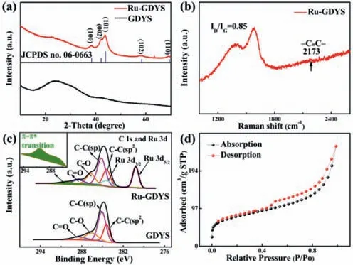
Fig.2. (a) XRD patterns of different catalysts and (b) Raman spectra of Ru-GDYS.(c) The high-resolution XPS spectra of C 1s and Ru 3d for Ru-GDYS and GDYS (d)N2 adsorption and desorption isotherms of Ru-GDYS.
Cyclic voltammetry (CV) test with Ru-GDYS and GDYS cathode between at a scan rate of 0.1 mV/s are conducted (Fig.3a).Compared with GDYS,it is observed that the Ru-GDYS based battery has strong anodic peak properly around 2.36 V corresponding to the CO2evolution reaction,and cathodic peak around 4.18 V,concerned in CO2reduction process.As shown in Fig.3b,the Ru-GDYS cathode delivers an ultrahigh discharge capacity of 15,030 mAh/g at 500 mA/g,distinctly exceeding GDYS cathode(11,016 mAh/g).Additionally,a reversible charged capacity of Ru-GDYS (14,668 mAh/g) is gained with a splendid coulombic effi-ciency of 97.6%,manifesting that a majority of discharged products are decomposed during the charging process.On the contrary,pure GDYS cathode displays low reversible capacity and poor coulombic efficiency.The result further affirms the superiority of Ru nanoparticles combined with GDYS.The rate performance tests are exhibited in Fig.3c and Fig.S9 (Supporting information).The discharge capacity of the Ru-GDYS cathode mildly declines to 13,382 mAh/g at 1000 mA/g,nevertheless,the capacity of GDYS drops quickly (7981 mAh/g).Under 1500 mA/g,the discharge capacity of Ru-GDYS (10,720 mAh/g) is more than twice that of GDYS cathode (4523 mAh/g).Unexpectedly,the Ru-GDYS cathode remains a significant discharged capacity of 8873 mAh/g at 2000 mA/g.On the contrary,the capacity based on GDYS cathode has reduced to 2709 mAh/g.The data confirms the superior rate performance with great CO2RR/CO2ER activities of Li–CO2batteries using Ru-GDYS electrode.The Ru-GDYS cathode is capable of operating over 120 cycles and stays steady at 500 mA/g with a curtailing capacity of 1000 mAh/g (Fig.3d).At the same time,the voltage gap (△V) is around 1.42 V at the 50thcycle.Although the voltage gap shows a mild increase after 120thcycle,it is still below within 1.67 V,which may be attributed to the synergy of excellent activity of Ru and the optimized development route invited by GDYS of discharge products [49].In contrast,under the same conditions,the Li–CO2battery with GDYS cathode only works 80 cycles with large polarization (△V=2.38 V) (Fig.3e).To acquire deep insight into the catalytic activity and superiority of the well-dispersed Ru nanoparticles,we further compare the first cycled curves of different electrodes (Fig.3f).It is important that the charge voltage plateaus of the Ru-GDYS cathode (3.61 V) is considerably lower than that of GDYS cathode (4.77 V) and the initial discharge/charge voltage gap is remarkably declined to 1.11 V,demonstrating the Ru nanoparticles of the Ru-GDYS composite possess superior competency for boosting CO2reduction reaction.Interestingly,commercial graphene (COMG) cathode also shows a short cycling life-span of merely 75 loops,lower than GDYS under the same condition (Fig.S10 in Supporting information),highlighting that the carbon carrier of GDYS has better activity and stability.Moreover,according to the comparison of their corresponding terminal potentials-cycle number profiles in Fig.3g,the difference of the terminal voltages of the Ru-GDYS involved Li–CO2cells on the average is around 1.42 V.It is much smaller than that of GDYS during a long roundtrip (>120 cycles),featuring a prominent cycling reliability.Unfortunately,battery with GDYS electrode suffers from great losses of polarization with high CO2ER terminal voltage and CO2RR terminal potential rapidly dropping below 2.0 V at 80thcycles.
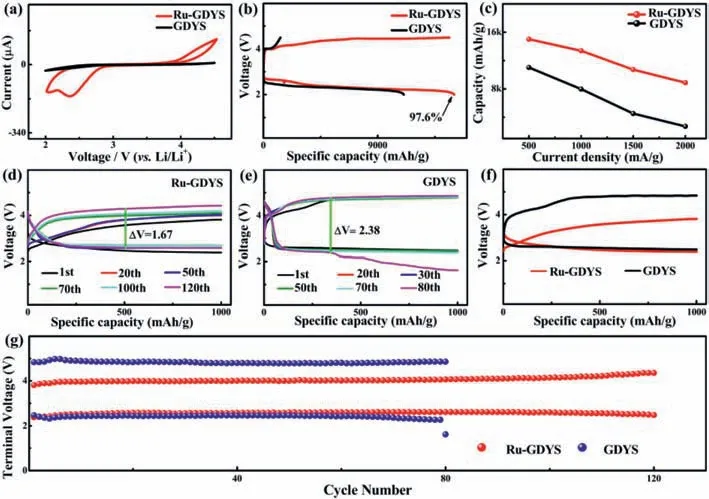
Fig.3. (a) CV experiments of the Li–CO2 batteries with Ru-GDYS and GDYS cathodes.(b) Full discharge/charge curves at 500 mA/g.(c) The discharge capacities of the Ru-GDYS cathode and GDYS cathode at different current density.Galvanostatic tests of (d) Ru-GDYS cathode and (e) GDYS cathode at 500 mA/g with fixed capacity of 1000 mAh/g.(f)Initial discharge/charge profiles at 500 mA/g.(g) Terminal voltages versus the cycle number of Ru-GDYS and GDYS cathodes based batteries.
The superiority of our elaborately designed Ru-GDYS is that a multi-functional laminar scaffold with anchored Ru nanoparticles can not only facilitate the storage of lithium metal and thus significantly increase the capacity of Li–CO2batteries,but also provide enough space for the reversible Li2CO3.The hierarchical porous construction and large surface area of Ru-GDYS can afford a superhighway for electrolyte permeation and CO2/Li+transport and provide enough available catalytic active sites for CO2RR/CO2ER electrochemical process in Li–CO2batteries.Fig.4a gives theexsituSEM images of Ru-GDYS cathode under the different states,which directly embodies the changes of morphology for the electrode.Compared with the pristine Ru-GDYS electrode (Fig.S11 in Supporting information),there are evenly filled with flower-like products composed of thin slices on the surface after discharging.Thanks to the superiority of the GDYS structure and the splendid activity of Ru nanoparticles,the discharge products are barely visible after following recharged progress,as same as the pristine Ru-GDYS cathode.Based on previous studies,the acetylenic bond of GDYS has the characteristic of active sites and can interact with Ru metal strongly [50],which not only reduces the energy barrier of CO2RR greatly,but also optimizes the formation of discharge products.Since the morphology and distribution of the discharge products are affected by the strong adsorption capacity of Ru species,the discharged Ru-GDYS cathode forms nanoflower-like products[51,52].Each nanosheet of cluster is thin and tightly bound,thus helping to improve the discharge capacity and enhancing the battery performance significantly.Conversely,SEM image of the discharged GDYS cathode (Fig.S12 in Supporting information) displays the cluttered products overlying the electrode and there are still clumps of undecomposed materials after recharging.
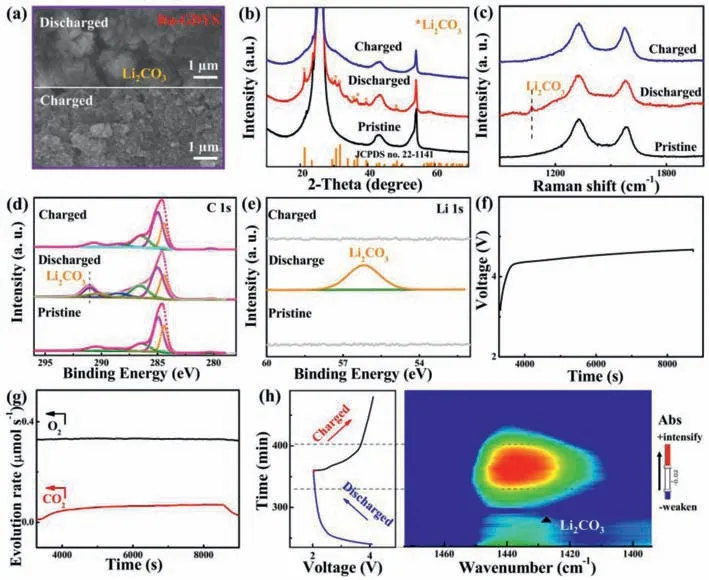
Fig.4. (a) SEM images of the Ru-GDYS cathode at different stages.(b) XRD pattern,(c) Raman spectra and XPS spectra of (d) C 1s and (e) Li 1s for Ru-GDYS cathodes at pristine,discharged,and recharged conditions.(f) Charge curve of a Ru-GDYS based Li–CO2 battery and (g) the synchronous evolution of CO2 and O2 detected by in-situ DEMS.(h) The time vs. voltage curve of Li–CO2 cells with Ru-GDYS cathode and the corresponding 2D contour plot of in-situ FT-IR spectrum.
The surplus products covered on the electrode surface conceal the active sites and enlarge the interface resistance between Li2CO3and catalyst [53].Fig.S13 (Supporting information) displays the impedance spectroscopy (EIS) spectra of Ru-GDYS and GDYS cathodes during cycling.The corresponding equivalent circuit of the EIS spectra has been shown in the inset of Fig.S13.A semicircle in the high frequency region represents the charge transfer resistance (Rct),implying the capability of charge transport between discharged products and cathodes [4,46].Since the insulating discharge products are constantly covered on the CO2cathode,theRctof Ru-GDYS involved Li–CO2cell increases from ∼231 ohm of the pristine state to ∼379 ohm at the discharged condition (Fig.S13a).After recharging,theRctof Li–CO2cell with Ru-GDYS returns to ∼274 ohm.On the contrary,theRctof GDYS (∼545 ohm)electrode is much larger than that of Ru-GDYS at full discharged stage.After recharging back,the recharged GDYS cathode shows unrecoveredRctof ∼416 ohm,which is higher than that of pristine stage (∼248 ohm) (Fig.S13b).It is consistent with the observed results from SEM images (Fig.S12c) that there are some undecomposed Li2CO3on the surface of the recharged GDYS electrode.To probe into the composition of the discharge product and reversibility during charge/discharge process,ex-situXRD and Raman are executed (Figs.4b and c).At discharged stage,many new broad peaks emerge compared with pristine cathode,which correspond to the typical characteristic of Li2CO3(JCPDS No.22–1141).Afterwards,every Li2CO3related diffraction peaks disappear entirely and a glossy curve reborn as the same as the pristine one during CO2evolution reaction.The result further proves that Li2CO3as one of the main products generates during discharge stage and fades away in the recharged period.Theex-situRaman experiment reveals the invertible formation/decomposition of Li2CO3(∼1072 cm−1) over cycling (Fig.4c) [54,55],which is consistent with the evolution of above SEM morphology.Furthermore,alterations in chemical states of elements of the Ru-GDYS cathode are characterized by XPS technology.Compared to the primitive C 1s high-resolution spectrum,a strong peak at around 290.9 eV appears which is due to the discharge product Li2CO3taking shape (Fig.4d).As disclosed in Li 1s XPS spectrum (Fig.4e),the peak at 56.1 eV of Li2CO3clusters almost vanishes absolutely after CO2RR in compliance with the foregoing conclusion [56,57].
To investigate the evolution of CO2gas of Li–CO2batteries during recharge stage,in-situdifferential electrochemical mass spectrometry (DEMS) is conducted.The Ru-GDYS-based battery is discharged 2 h under 300 μA in CO2gas.Then,the Ar stream is injected into DEMS system until the CO2concentration is very low and the airflow of Ar gas is stable (Fig.S14 in Supporting information).Finally,the battery is charged 2 h under 300 μA in Ar gas (Fig.4f).During this process,only CO2is generated with no change of O2.It further confirms that Li2CO3is the main product of discharging and mainly produces CO2gas under the condition of charging (Fig.4g) [58,59].To further gain insight of the mechanism about electrocatalysis of Ru-GDYS material over cycling,anin-situFourier transform-infrared spectroscopy (FT-IR) experiment is also applied.The assembledin-situFT-IR cell is examined by galvanostatic charge-discharge cycling test at 220 μA for 2 h under CO2atmosphere in parallel with FT-IR monitor.The corresponded timevs.voltage curve of the cell during a complete (dis)charge cycling is shown in Fig.4h.In corresponding 2D contour plot,the left side of color bar represents the strong and weak direction of the absorbance (Abs).In the wavenumber of 1400∼1450 cm−1,a symmetric evolution in intensity is exhibited,confirming the gradual formation/decomposition of Li2CO3during cycling [60,61].Moreover,thein-situFT-IR spectrum in discharge process from 3.0 V to 2.0 V,an upward broad peak related to Li2CO3arises gradually at about 1420 cm−1(Fig.S15a in Supporting information).Subsequently,the peak of Li2CO3gradually weakens during the charging process and even disappears after full charged (Fig.S15b in Supporting information),suggesting that Li2CO3can be decomposed almost reversibly with the help of Ru-GDYS catalyst.Hence,it obviously proves that the Ru-GDYS catalyst can notably promote the reversible processes and reduce the charge voltage about the Li–CO2cell due to the synergy between Ru nanoparticles and GDYS.
In summary,we fabricate a highly distributed Ru nanoparticles anchored on GDY scaffold as advanced electrocatalyst for highperformance Li–CO2battery.GDY scaffold with a great part of acetylenic bonds and special pores,not only possesses a splendid ability for metal adsorption but also has sufficient space for Li2CO3production and decomposition.The prepared Ru-GDYS composite has the advantages of high-efficiency active sites,fast kinetic behavior of CO2ER/CO2RR and excellent structure,which greatly enhances CO2conversion property in terms of capacity,voltage gap and rate capability.Due to outstanding catalytic activity of Ru-GDYS derived from the structural superiority and efficient modification of electronic structure,the Li–CO2battery has a remarkable rate capacity of reserving 8873 mAh/g at 2 A/g,great cycling performance of 120 cycles with a narrow overpotential below 1.67 V,low charge voltage of 3.61 V at initial cycle as well as a high coulombic efficiency of 97.6% at 500 mA/g.Ex/in-situtechnologies prove that the synergy between Ru nanoparticles and acetylene bonds of GDYS can greatly boost the CO2ER/CO2RR property of Ru-GDYS and further accelerate the reversible generation and decomposition of Li2CO3in Li–CO2battery.This work supplies new insights on design of highly efficient cathode catalysts in the field of metal air battery and beyond.
Declaration of competing interest
The authors declare that they have no known competing financial interests or personal relationships that could have appeared to influence the work reported in this paper.
Acknowledgments
This work was supported by the National Natural Science Foundation of China (Nos.21971132 and 52072197),Outstanding Youth Foundation of Shandong Province,China (No.ZR2019JQ14),Youth Innovation and Technology Foundation of Shandong Higher Education Institutions,China (No.2019KJC004),Major Scientific and Technological Innovation Project (No.2019JZZY020405),Major Basic Research Program of Natural Science Foundation of Shandong Province (No.ZR2020ZD09),Taishan Scholar Young Talent Program(No.tsqn201909114),the Key Laboratory of Resource Chemistry,Ministry of Education (No.KLRC_ME2101),Scientific and Technological Innovation Promotion Project for Small-medium Enterprises of Shandong Province (No.2022TSGC1257),Major Research Program of Jining City (No.2020ZDZP024) and The 111 Project of China (No.D20017).
Supplementary materials
Supplementary material associated with this article can be found,in the online version,at doi:10.1016/j.cclet.2023.108352.
 Chinese Chemical Letters2023年12期
- Chinese Chemical Letters的其它文章
- Rocking-chair ammonium ion battery with high rate and long-cycle life
- Mitigating the dissolution of V2O5 in aqueous ZnSO4 electrolyte through Ti-doping for zinc storage
- Cost-effective natural graphite reengineering technology for lithium ion batteries
- Alkyl-thiophene-alkyl linkers to construct double-cable conjugated polymers for single-component organic solar cells
- Modulating the p-band center of carbon nanofibers derived from Co spin state as anode for high-power sodium storage
- The compatibly large nonlinear optical effect and high laser-induced damage threshold in a thiophosphate CsInP2S7 constructed with[P2S7]4- and [InS6]9-
